


Function and working principle of bending machine axis
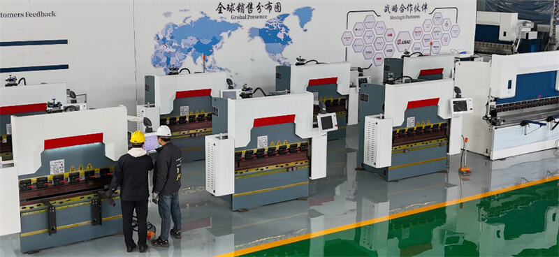
A CNC bending machine is a bending machine controlled by a computer numerical control (CNC) system. CNC bending machines can fold metal sheets into various profiles. The bending accuracy and quantity are related to the synchronization system, hydraulic system and back gauge. The function of these components is affected by the number of axes of the CNC bending machine. Understanding these axes is essential for selecting, configuring and effectively operating a bending machine.
1. What axes are there on a bending machine?
The CNC system controls the movement of the bending machine axes. The bending machine axes are named according to their position in the spatial coordinates. The bending machine axis refers to the mechanical element that controls the movement of different parts of the bending machine.
These movements include up and down movement, front and back movement, left and right movement, and even fine-tuning of the bending angle of the metal plate. The precise movement of the axis ensures the accurate position and angle of the metal in the bending machine, facilitating precise bending operations.
The required accuracy of the workpiece determines the number of axes required for the bending machine. Typically, a CNC bending machine has at least three sets of controlled axes: Y1/Y2, X and R axes. These axes are used to control the movement of the backgauge, slide, and other components.
Torsion axis press brakes are used to bend simple workpieces and have at least two axes, which are used to control the Y axis of the slide and the X axis of the backgauge. The simplest press brakes only need a Y axis to control the up and down movement of the slide.
The accuracy and repeatability of the Y axis movement determines the accuracy of the bend angle. The control system uses axes to control the movement of different components, thereby controlling the bend angle and size.
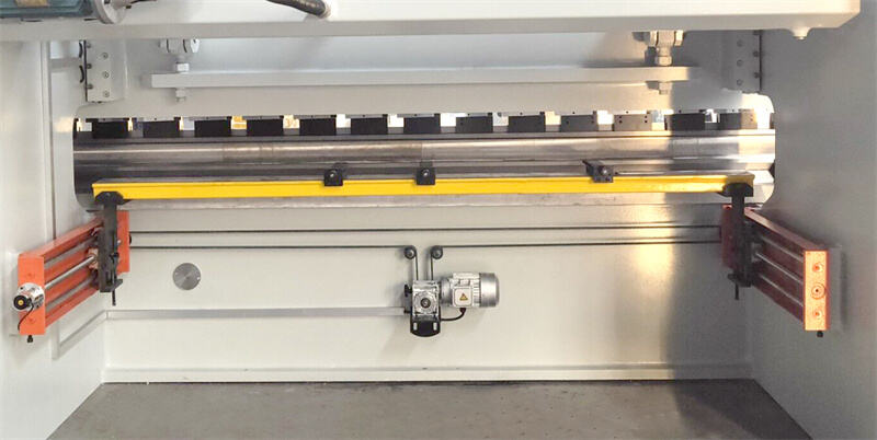
2. What is the backgauge of a press brake?
The backgauge of a press brake is a component that helps position and align the metal sheet before bending. It is located at the rear of the bending tool and moves along the X axis.
The backgauge consists of a series of fingers and blocks that can be adjusted to the desired position depending on the desired bend length. These fingers can be operated manually, electrically, or by a CNC system.
The backgauge is designed to ensure the consistency and accurate position of the metal sheet when bending. It achieves precise bend angles, lengths, and geometries by controlling the depth and position between the metal sheet and the bending tool. It plays a vital role in increasing productivity, reducing equipment setup time and ensuring repeatability of bending operations. It eliminates the requirement for manual measurement and estimation, resulting in a consistent and efficient bending process.
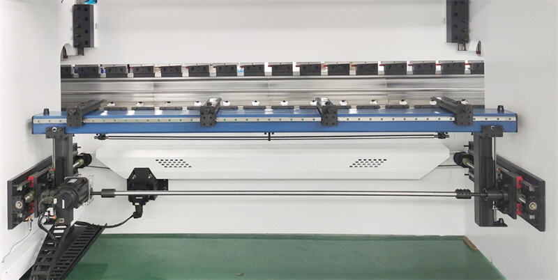
In modern bending systems, the back gauge can be integrated with the press brake controller for automatic positioning and control. This integration provides seamless cooperation between the back gauge and press brake axes, which helps achieve precise bending operations and accurate and repeatable bends.
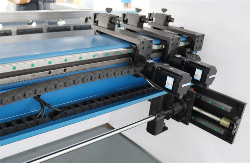
The back gauge is controlled by the CNC system to accurately position the sheet metal. Typically, the back gauge has at least one axis, and more advanced systems can have up to six axes. Independent motors drive each axis to slide back and forth in a specific direction. Ball screws, timing belts, and axes work together to achieve synchronized motion. These precise, repeating actions ensure accuracy in each batch of workpieces. Optical sensors and CNC programming on the press brake can also be used for positioning.
Relationship between back gauge and axis
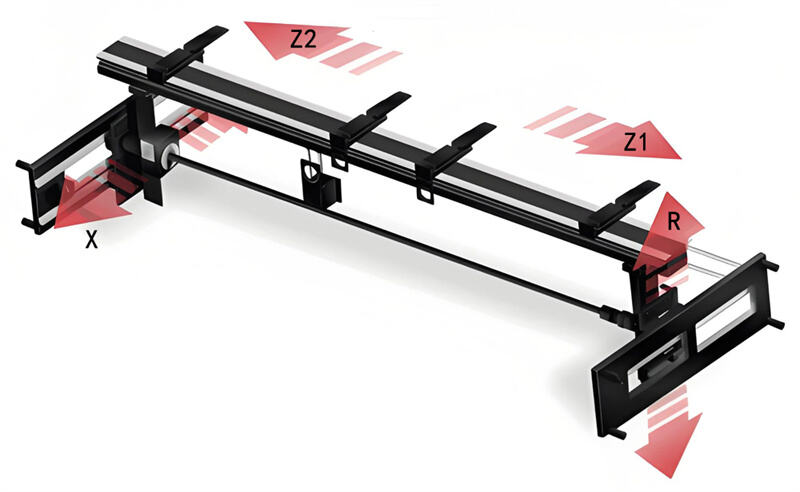
The back gauge of the press brake is closely related to the press brake axis and mutually ensures the accuracy and precision of the bending operation. Bending axes refer to the different moving axes inside a press brake, such as the X-axis, Y-axis, Z-axis, and R-axis.
These axes control the positioning of the bending tool and the movement of the metal sheet during the bending process. On the other hand, the position and height of the backgauge can be controlled by adjusting the press brake axes. By controlling the position of the Y-axis and X-axis, the backgauge can be aligned with the workpiece, ensuring precision and consistency in bending.
Nowadays, the backgauge and press brake are usually integrated and controlled by a CNC system. This integration allows for automatic positioning and precise control of the press brake axes and backgauge, enabling an efficient and precise bending process.
3. Main Groups of Controlled Axes
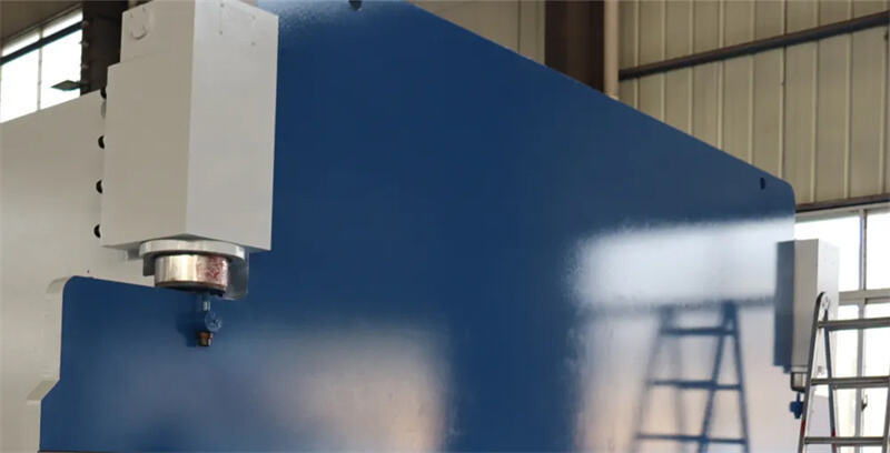
Y-axis Vertical Plunger Movement
The Y-axis represents the vertical axis of the press brake moving in the depth direction. The Y-axis controls the vertical movement of the slide. The slide moves up and down to bend the metal workpiece.
In air bending, the up and down movement of the top beam becomes stable and uniform under the drive of the Y-axis. The Y-axis can be divided into the Y1-axis and the Y2-axis, which are located at the top of the two columns respectively.
Y1 and Y2 control the up and down movement of the cylinders on both sides of the bending machine. Driven by the Y axis, the up and down movement of the top beam becomes stable and uniform. Y1 and Y2 are the full closed-loop control axes of the left and right cylinders respectively. Y1 and Y2 can also independently adjust the level of the top beam.
Y1: Full closed-loop control axis of the left cylinder
Y2: Full closed-loop control axis of the right cylinder
4. Axis on the back gauge
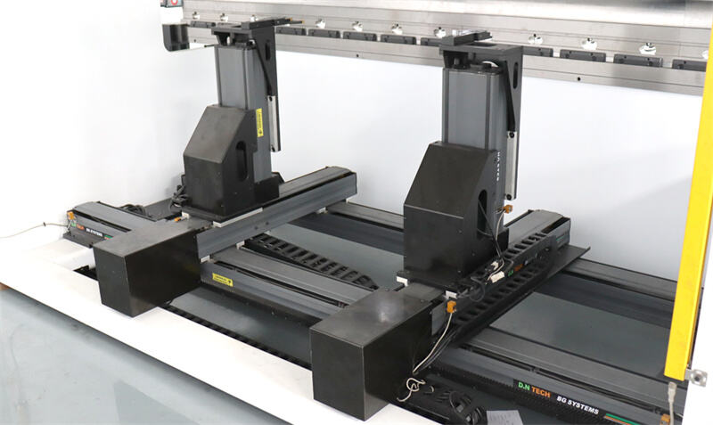
The more complex the workpiece, the more axes are needed for the backgauge. The backgauge can have up to 6 axes, which are available in different variants. Each axis has an independent drive motor to ensure positioning accuracy.
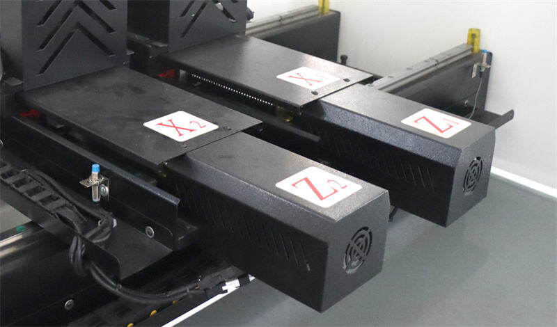
X-axis: Horizontal backgauge movement
The X-axis manages the horizontal movement of the backgauge, accurately positioning the metal workpiece under the slide. By moving horizontally, the X-axis ensures that every bend is correctly aligned. The X-axis is a very important axis in the bending process, which determines the flange length of the workpiece.
The fingers on the X-axis position the metal sheet as it is pushed onto the backgauge. The X-axis of the press brake has a fixed width of movement, but it can be divided into the X1 and X2 axes.
The X1 and X2 axes allow the fingers of the backgauge to move independently back and forth on the left and right sides. The X-axis controls the backgauge's forward and backward movement. This axis is essential for achieving precise positioning and repeatability.
The fingers accurately position the sheet as soon as it enters the backgauge. X1 is the forward and backward movement axis of the left stop finger, and X2 is the forward and backward movement axis of the right stop finger. The X1 and X2 axes can measure the length of the flange of the workpiece being formed.
X1: Left stop finger back and forth movement axis
X2: Right stop finger back and forth movement axis
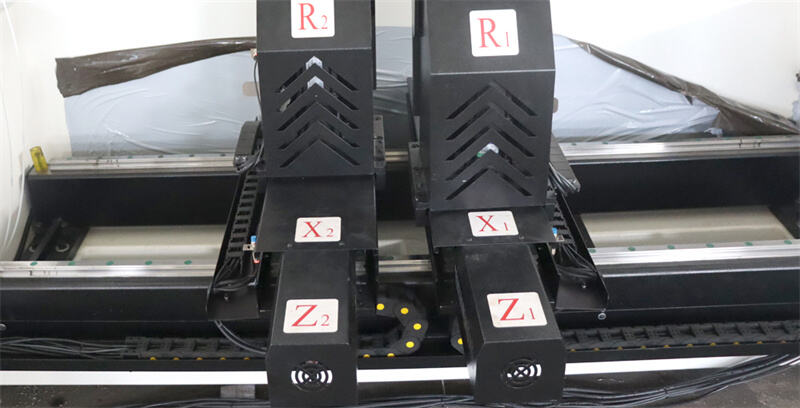
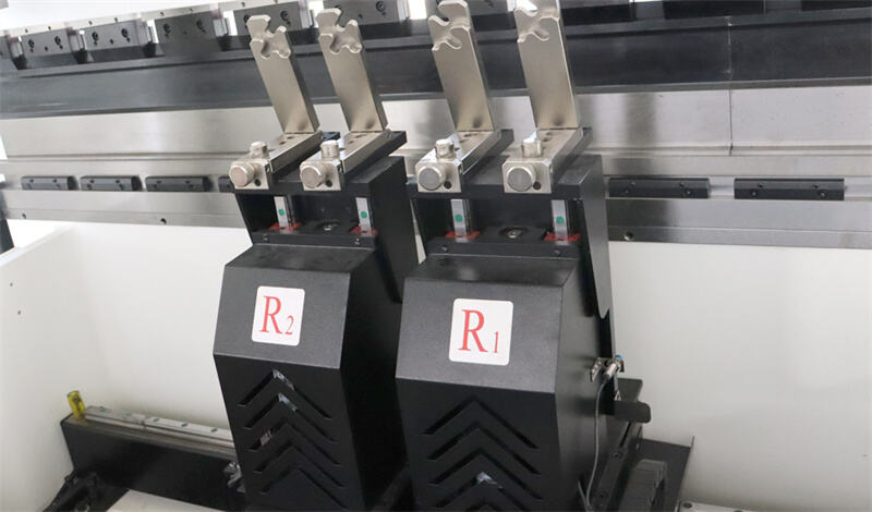
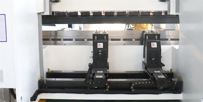
R-axis vertical backstop movement
The R-axis controls the vertical movement of the backstop, which is essential for adjusting its height to accommodate different flange heights and material thicknesses. The height of the R-axis is automatically adjusted based on the height of the mold.
The R-axis is divided into R1 and R2. These two axes can move up and down independently on the left and right sides. Depending on the complexity of the part, these two axes can be positioned at different distances. The R-axis can also position a bent flange that moves under the bending plane.
R1: Left stop finger up and down movement axis
R2: Right stop finger up and down movement axis
Z-axis: Lateral backgauge movement
The Z-axis controls the lateral movement of the backgauge fingers, allowing independent positioning of the fingers. The Z-axis is useful when the bending of the workpiece requires multiple bending steps and cycles, or when large or complex workpieces need to be processed. The Z1 and Z2 axes can be independently positioned through programming.
Using Z-axis positioning can improve the accuracy and efficiency of bending. Z-axis positioning provides uniform support for bending longer sheets. The movement of the Z-axis determines the horizontal position of the backgauge to adapt to the width and horizontal position requirements of different workpieces.
Z1: Left and right movement axis of the left stop finger
Z2: Left and right movement axis of the right stop finger
5. Other Axes on a Press Brake
Press brakes play a pivotal role in the world of advanced metal fabrication. In addition to the common axes mentioned above, modern press brakes are equipped with many additional axes for added control and flexibility. Such as the V-axis, L-axis, and Delta X-axis.
V-axis: Crown Compensation
The special feature of the V-axis introduces the concept of bow compensation. When bending long metal parts, bowing often occurs in the center due to the pressure caused by the press brake, resulting in an imperfect bend. To eliminate this, the V-axis adjusts the machine bed and compensates for deflection to ensure a precise straight bend across the entire length of the material.
The L-axis controls the horizontal movement of the back gauge. This side-to-side movement adds flexibility to handle wider metal sheets or off-center bends. It adds a great deal of flexibility to press brake operation, especially when handling complex attachments and precise bending operations.
Delta X-axis: Independent Back Gauge Finger Movement
The Delta X-axis controls the independent movement of the back gauge fingers, allowing each finger to move independently, providing a huge advantage for complex bending operations or asymmetrical parts. By independently adjusting the position of each finger, the Delta X-axis enables high-precision bends in complex and custom machining tasks.
Most importantly, these axes provide greater precision and accuracy in press brake operations. Understanding their capabilities and how to optimize their use can greatly improve the efficiency, precision, and overall performance of metal bending and machining.
As technology continues to advance, many advanced axes and features will be introduced to push the boundaries of what is possible in the world of metalworking.
6. Configuration and Selection
Minimum Configuration
For basic operation, a CNC press brake must have at least one Y-axis, which controls the vertical movement of the slide. A more common and versatile configuration is a three-axis setup, which includes:
Y-axis (y1 and y2 axes): controls the vertical movement of the slide. Independent control of Y1 and Y2 increases precision, especially for asymmetrical workpieces.
X-axis: manages the horizontal movement of the backgauge, ensuring precise positioning of the workpiece.
R-axis: controls the vertical movement of the backgauge fingers to accommodate different flange heights and material thicknesses.
For example, a three-axis setup can efficiently handle basic bending tasks, such as forming uniform 90-degree bends in metal sheets to make simple brackets.

Advanced Axis Configurations
For more complex bending tasks and higher precision, additional axes can be integrated into the CNC press brake. These advanced configurations include:
Z-axis (Z1 and Z2): controls the lateral movement of the backgauge fingers. Independent Z1 and Z2 axes enable precise positioning of each finger, which is critical for complex workpieces.
Delta X-axis: Allows each finger to move horizontally independently along the X-axis. This is particularly useful for handling asymmetrical parts and making complex bends.
Crown Compensation (V-axis): Adjusts for deviations in the press brake bed during the bending process, ensuring even pressure distribution and consistent bend angles.
For example, to make complex, multi-bend components with different angles and sizes, you need the precision and flexibility these additional axes provide.
Choosing the Right Axes
When deciding on the number of axes for your CNC press brake, consider the following factors:
Workpiece Complexity
If you frequently machine complex or asymmetrical parts, additional axes such as Z1/Z2 and Delta X are essential. These axes provide the flexibility and precision needed to handle complex bends and different angles.
Precision Requirements
Higher precision requirements require more advanced configurations. Independent control of Y1 and Y2, combined with crown compensation, ensures that even the most demanding bends are completed with precision.
Production Volume
For high-volume production, a CNC press brake equipped with multiple axes can significantly reduce setup time and increase production output. Automatic backgauge adjustment and precise positioning minimize manual intervention and improve overall efficiency.
Balancing Cost and Capability
While additional axes can enhance the functionality and precision of a CNC press brake, they also increase the cost of the machine. It is important to balance the budget with the needs of the operation:
Basic Configuration: Suitable for simple bending tasks and smaller budgets. A three-axis setup (Y1/Y2, X, R) provides a good balance between functionality and cost.
Intermediate Configuration: Suitable for medium complexity and precision requirements. Adding Z1/Z2 axes to the basic setup increases flexibility without significantly increasing costs.
Advanced Configuration: Necessary for high-precision and complex bending operations. Including Delta X and crown compensation (V-axis) in the setup ensures best-in-class performance, but at a higher cost.
In summary, the number of axes in a press brake determines the complexity and precision of the workpiece. However, the more axes there are, the higher the machine purchase cost. If there are no complex bending requirements, a basic three-axis or four-axis press brake is all you need. If you need to process complex and precise workpieces, the more axes you have, the better the bending results.
The bending accuracy of a press brake depends on the movement of its axes. A press brake should have at least one Y-axis to control the up and down movement of the slide. The Y-axis is the most important axis because it controls the bending angle of the workpiece. The most common press brake is a three-axis configuration, equipped with Y1/Y2, X and R axes.
When buying a press brake, it is important to choose the appropriate number of axes according to the complexity of the workpiece. JUGAO CNC MACHINE can help you choose the most suitable press brake according to your budget.

