


Detailed Setup Steps for the DELEM DA-69S Settings Mode
Table of Contents
• Step 1: Accessing the DELEM DA-69S Settings Mode
• Step 2: Configuring General Parameters
• Step 3: Setting Material Properties
• Step 4: Backup and Restore Options
◦ Product Backup and Restore
◦ Tool Backup and Restore
◦ Backup and Restore for Tables and Settings
◦ Automatic Scheduled Backups
◦ Directory Navigation
• Step 5: Tailoring Program Settings
• Step 6: Defining Default Values
• Step 7: Adjusting Computation Settings
• Step 8: Fine-Tuning Production Settings
◦ Intermediate X for Z-Movement
◦ Intermediate R for X-Movement
◦ Intermediate R for Z-Movement
• Step 9: Configuring Network and Time Settings
◦ Production Time Calculation
◦ Time Settings
◦ Network Settings
• Frequently Asked Questions (FAQ)
◦ Can I customize parameters in the DELEM DA-69S Settings Mode?
◦ Does the DELEM DA-69S Settings Mode have a reset function?
◦ What should I do if the DELEM DA-69S Settings Mode is unresponsive?
• Conclusion
If you are looking to optimize the operation of the DELEM DA-69S Settings Mode, this article is exactly the guide you need. This document will break down the core setup steps of the DELEM DA-69S in a step-by-step manner, helping you clearly understand each operational process. Whether you are configuring the device for the first time or need to fine-tune existing parameters, this guide will assist you in improving operational efficiency and accuracy. Next, let’s learn how to configure the DELEM DA-69S Settings Mode to achieve the optimal performance of the device.
Step 1: Accessing the DELEM DA-69S Settings Mode

To start configuring the DELEM DA-69S, tap the navigation button labeled "Settings" to enter the Settings Mode. This mode serves as a key gateway to optimizing the machine's performance, containing a variety of adjustable settings. These settings are categorized by tabs, and you can switch between tabs by tapping and dragging when necessary.
Since the screen can only display a limited number of tabs at one time, if you need to view all available tabs, you can drag the tab bar vertically to select the target tab.
Step 2: Configuring General Parameters
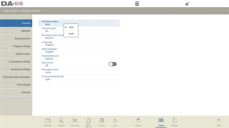
In the "General" tab, you can adjust basic parameters, including the following:
• Units of Measurement: For length, you can choose between inches and millimeters; for force, you can select between Tons and KN.
• User Interface Language: You can select the interface language according to your preference. If you need additional help languages, you can also install them here.
◦ Help Language:
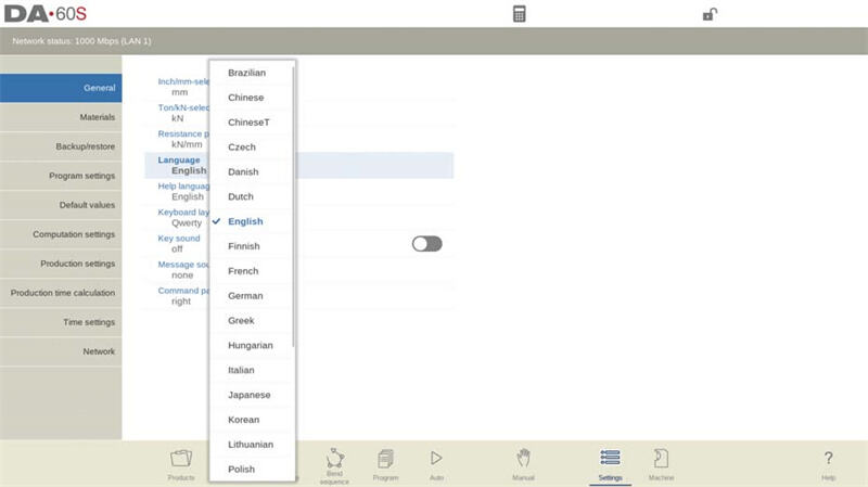
In the DELEM DA-69S Settings Mode, the default language of the online Help function is the same as the user interface language. If the corresponding online Help resource for that language is not available, it will automatically switch to English. When "Help Language" is selected in the Settings Mode, the "Add Help Language" function will appear. Through this function, you can install a new help language on the controller. Ensure that the required help file is stored in the controller's disk or another accessible location (such as a network or USB drive), and the system will automatically recognize and complete the installation.
• Keyboard Layout: You can select your preferred keyboard layout, with options including Qwerty, Qwertz, and Azerty.

• Key Sound: You can enable or disable the key sound of the input panel according to your needs.
• Message Sound: You can set whether to enable the prompt sound based on message types, with the following specific options:
◦ All messages: Prompt sound is triggered for all messages.
◦ Errors + Warnings: Prompt sound is triggered only for error and warning messages.
◦ Errors: Prompt sound is triggered only for error messages.
◦ None: No prompt sound is triggered for any messages.
• Command Panel Position: You can switch the command panel to be displayed on the left side of the screen.
Step 3: Setting Material Properties
In the "Materials" tab, you can preset the properties of up to 99 different materials. Each material has 5 properties that can be viewed and edited, as detailed below:
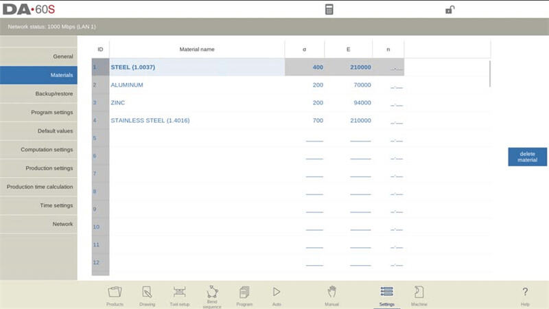
1. Material Name:
◦ This name will be displayed on the programming interface of the DELEM DA-69S.
◦ The maximum length is limited to 25 characters, and it must start with a letter (not a number).
1. Tensile Strength: You need to enter the tensile strength value of the material, which is a key parameter for achieving accurate bending calculations in the DELEM DA-69S Settings Mode.
2. E Module (Modulus of Elasticity): You need to enter the modulus of elasticity (also known as E-module) of the material, which is crucial for the calculation function in the Settings Mode.
3. Strain Hardening Exponent (n-value):
◦ This parameter should be provided by the material supplier (similar to tensile strength and E-module).
◦ An accurate n-value can improve the precision of inner radius calculation, thereby optimizing the accuracy of bending depth and bend allowance.
◦ The value range is 0.01-1.00, with the default value being ". " (indicating that the n-value is inactive). If you enter 0, the system will reset the value to "._ _".
◦ The typical n-value for mild steel is 0.21.
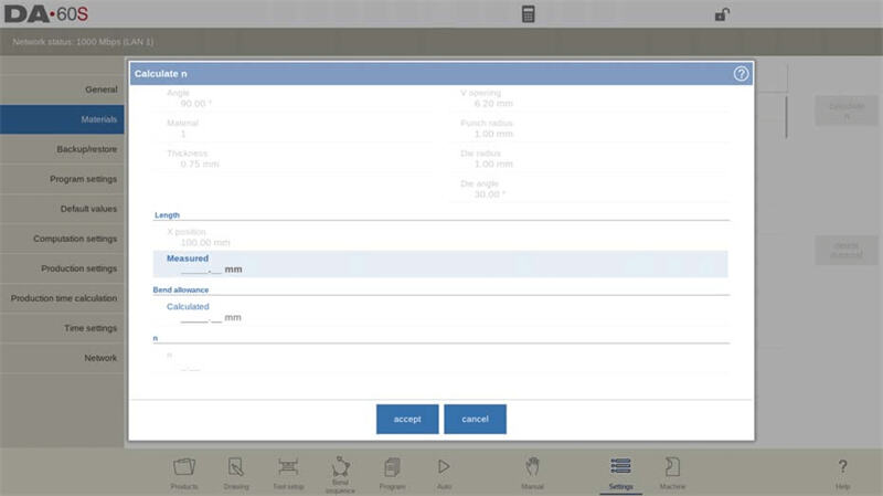
1. Calculate n:
◦ The n-value is preferably provided by the supplier. If it is not available, it can also be derived from the bend allowance.
◦ Without a bend allowance table: Perform a test bend in Manual mode, then switch to the material table, tap "Calculate n" in the DELEM DA-69S Settings Mode, and enter the measured side length after bending. The system will calculate the bend allowance and strain hardening exponent (n-value) based on the difference between the programmed X-axis value and the measured side length. The calculation accuracy depends on the accuracy of sheet thickness, tool parameters, and side length measurement.
◦
◦ With a bend allowance table: In the DELEM DA-69S Settings Mode, when the bend allowance table is active, the strain hardening exponent can be derived directly. Select the n-value parameter of a material and tap "Calculate n"; the result will be displayed in the input field.
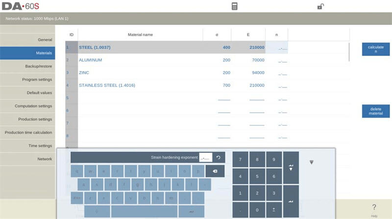
Materials are sorted by ID number. You can adjust the sorting method by clicking the column header. To modify material properties, select the target material and edit the values directly; to delete a material, select it and execute the "Delete Material" operation; to add a new material, select a blank row and enter the values for each property.
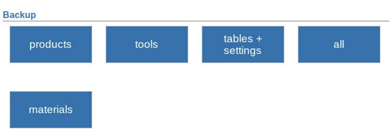
Step 4: Backup and Restore Options
In the "Backup/Restore" tab, you can back up products, tools, and settings to ensure data security. For backup, you can select media such as a USB drive or network storage. The specific operations are as follows:
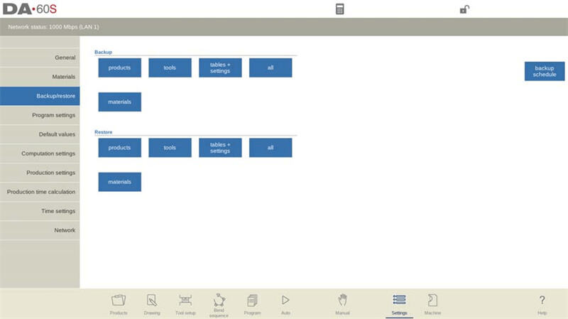
When selecting a backup directory, you first need to specify the storage device (such as a USB drive or network storage), then select a specific directory. The available range of devices depends on the storage devices currently connected to the controller, and you can create and select new directories as needed. In addition, the backup locations for products and tools can be set independently.
Product Backup and Restore

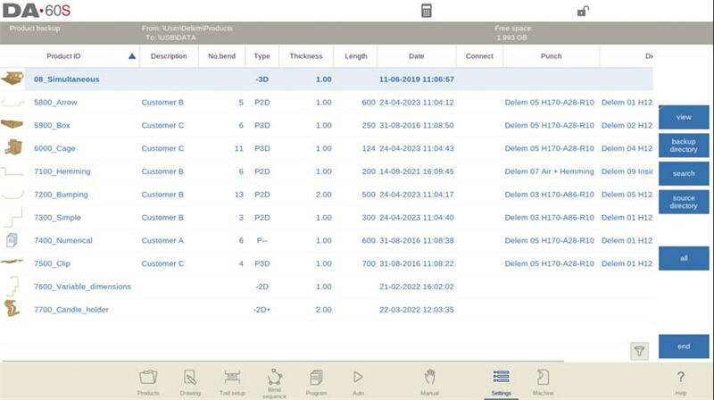
• Product Backup: In the "Backup" section of the "Backup/Restore" page, select "Products". After setting the initial backup directory, you will enter the product backup interface, which displays the list of products in the selected directory. The specific operation steps are as follows:
a. Tap a product in the list to select the item to be backed up; a backup marker will appear after selection.
b. If a file with the same name already exists in the backup directory, confirm whether to overwrite it.
c. If you need to back up all products at once, simply tap "All".
d. You can adjust the source path of the products through "Source Directory" and set the storage path of the backup files through "Backup Directory".
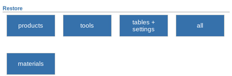
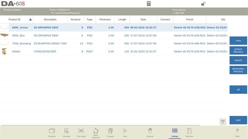
• Product Restore: In the "Restore" section of the "Backup/Restore" page, select "Products". After setting the initial restore directory, you will enter the product restore interface, which displays the list of products in the selected directory. The specific operation steps are as follows:
a. Tap a product in the list to select the item to be restored; a restore marker will appear after selection.
b. If a file with the same name already exists in the controller, confirm whether to overwrite it.
c. You can adjust the source path of the restore files through "Restore Directory" and set the storage path of the restored files in the controller through "Destination Directory".
Tool Backup and Restore
• Tool Backup: In the "Backup" section of the "Backup/Restore" page, select "Tools". After setting the initial backup directory, you will enter the tool backup interface. Through this interface, you can back up tool data (including punches, dies, and machine shapes) in the controller, and the operation process is consistent with product backup.
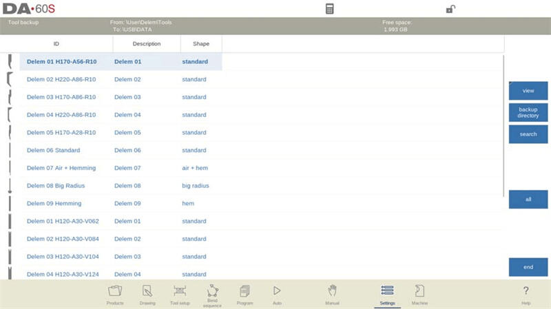
• Tool Restore: The operation process is consistent with product restore. After selecting "Tools" in the "Restore" section, follow the prompts to complete the restore operation.
Backup and Restore for Tables and Settings
In the DELEM DA-69S Settings Mode, the "Backup/Restore" tab also supports the backup and restore of user-defined settings and tables. The operation process is consistent with the backup and restore of products and tools. In addition, the "All" function can automatically complete the backup or restore of products, tools, tables, and settings in sequence, greatly simplifying the operation process.
Automatic Scheduled Backups
In the DELEM DA-69S Settings Mode, you can set the "Backup All" function to run automatically through the "Backup Schedule" function on the "Backup/Restore" page. The specific steps are as follows:
1. Set the backup interval (optional range: 1-31 days).
2. When the controller is in a ready state and the backup time is reached, the system will pop up a prompt asking whether to back up immediately or remind later.
3. The default reminder interval is 1 hour, which can be adjusted to 1-24 hours according to needs.
4. Select an appropriate backup location to achieve systematic device management.
Directory Navigation
When using the "Backup Directory" function, the system will pop up a new window displaying all available backup directories. Through this window, you can browse the directory structure of the storage device. The specific operations are as follows:
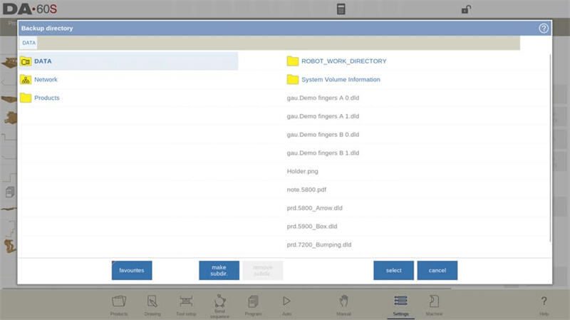
• Device Switching: Click the top-level directory, select the target storage device, and then access the corresponding subdirectory.
• Network Connection: If network storage exists, select "Network", select the target network volume, and then operate in the same way as with local devices.
• Directory Management: Use the "Make Subdir" function to create a new subdirectory and the "Remove Subdir" function to delete an existing subdirectory.
• Subdirectory Selection: Tap the target subdirectory to enter it, then tap "Select" to confirm that this directory is the backup directory.
Step 5: Tailoring Program Settings
Access the "Program Settings" tab to adjust parameters that affect the production process, as detailed below:
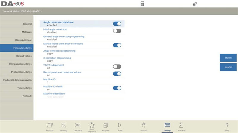
• Angle Correction Database: Enabling this function in the DELEM DA-69S Settings Mode allows angle correction data in Automatic Mode to be stored in the product program for subsequent reuse. After enabling, the system will check whether there is correction data for similar bends during production and automatically provide it if available. At the same time, new correction data generated during production will be synchronously updated to the database.
◦ Criteria for determining "similar bends": Material properties, sheet thickness, die opening size, die radius, and punch radius must be completely consistent, and the angle difference must not exceed 10°. If the angle difference between adjacent bends does not exceed 5°, the system will provide interpolated correction data.
• Initial Angle Correction: This function allows small angle adjustments to be set independently of the "Angle Correction Database". This parameter can be accessed on the "Corrections" page in both Automatic Mode and Manual Mode (it is not displayed on the main page of these two modes). The total angle correction value is the sum of the "visual correction value" and the "initial correction value".
◦ Example: If the programmed angle correction value is -8° and the initial angle correction value is -6°, the total correction value remains unchanged; at this time, the visual correction value will adjust from -8° to -2°.
◦ Function Switch: Set to "Enabled" to allow initial angle correction on the "Corrections" page; set to "Disabled" to restrict the use of this function.
• General Angle Correction Programming: This allows the setting of general angle corrections applicable to all bends in the program. This correction is not related to specific bend angles and is therefore not stored in the Angle Correction Database.
◦ Disabled: General angle correction is not enabled.
◦ Enabled: Only G-correction α1 (G-corr. α1) is enabled.
◦ α1 and α2: Both G-correction α1 and G-correction α2 (G-corr. α1 and G-corr. α2) are enabled.
• Manual Mode Store Angle Corrections: After enabling this function, angle correction data set in Manual Mode can be stored; this data is derived from bending results in Manual Mode and can be used for product programming later.
• Angle Correction Programming: When modifying angle corrections in Production Mode, this parameter is used to set the association mode between Cα1 and Cα2:
◦ Copy: When Cα1 is modified, the value of Cα1 is automatically copied to Cα2.
◦ Delta: When Cα1 is modified, the difference between Cα1 and Cα2 remains unchanged.
◦ Independent: Cα1 and Cα2 can be modified independently without affecting each other.
• X Correction Programming: When modifying X-axis corrections in Production Mode (only available when the device is equipped with an X2-axis), this parameter is used to set the association mode between CX1 and CX2. The options are the same as those for "Angle Correction Programming" (Copy, Delta, Independent).
• Y1/Y2 Independent: This sets whether the Y1-axis and Y2-axis can be programmed independently:
◦ Off: Single Y-axis programming mode is adopted.
◦ On: The Y1-axis and Y2-axis can be programmed independently.
• Recomputation of Numerical Values: In Manual Mode and Program Mode, parameters can be programmed one by one; this parameter is used to set "whether other parameters affected by a parameter modification are automatically recomputed":
◦ Disabled: Affected parameters are only recomputed when the parameter is re-entered and the suggested modified value is confirmed.
◦ Enabled: After modifying a parameter, the affected parameters are automatically recomputed.
• Machine ID and Check: In the DELEM DA-69S Settings Mode, a unique "Machine ID" must be assigned to each bending machine in the factory. The role of this ID is: when loading a program from a backup medium, the system will verify whether the Machine ID matches; if it does not match, the operation can only continue after user confirmation, otherwise the operation is terminated. If you need to simplify the process, you can also disable the Machine ID check function.
• Machine Description: You can enter detailed machine description information in the DELEM DA-69S configuration. This information will be displayed in the offline software Profile-T to help users quickly identify the machine corresponding to each controller.
Step 6: Defining Default Values
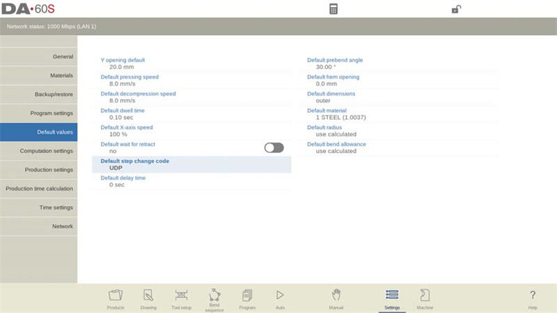
In the DELEM DA-69S Settings Mode, defining default values can optimize operational efficiency. The specific default parameters that can be set are as follows:
• Y Opening Default: Sets the initial opening value of the Y-axis in new programs.
• Default Pressing Speed: Sets the initial speed of the pressing action in bending programs.
• Default Decompression Speed: Sets the initial speed of the decompression action in bending programs.
• Default Dwell Time: Sets the initial time of the dwell action in bending programs.
• Default X-axis Speed: Sets the initial operating speed of the X-axis in new bending programs.
• Default Wait for Retract: Sets the default time for the controller to wait for the retract action in bending programs to define the device behavior.
• Default Step Change Code: Controls the timing of step switching in bending programs through a specified code.
• Default Delay Time: Adjusts the waiting time of the X-axis during step switching to improve product handling efficiency.
• Default Prebend Angle: Sets the default prebend angle for graphical products.
• Default Hem Opening: Calculates the beam position during hem bending, with an initial value of 0.0mm (to ensure full flange contact).
• Default Dimensions: Sets the default dimension type (inner dimension or outer dimension) for graphical product drawings.
• Default Material: Sets the initial material selection for new products or new programs.
• Default Radius: Sets the initial value of the radius in the product property dialog box.
• Default Bend Allowance: Sets the initial value of the bend allowance in product properties.
Mastering these default settings of the DELEM DA-69S can help you accurately configure bending programs and product drawings, achieving dual improvements in operational precision and efficiency.
Step 7: Adjusting Computation Settings
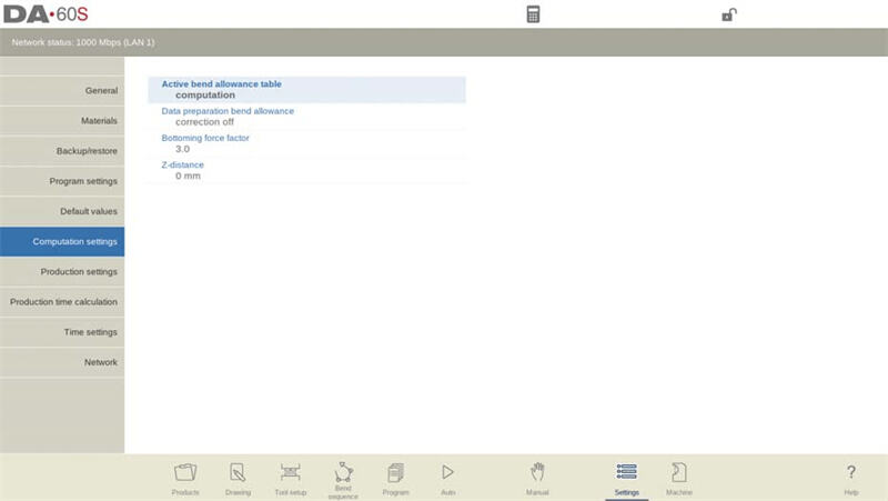
The DELEM DA-69S controller provides two methods for calculating bend allowance, as detailed below:
1. Computation: Uses the standard formula built into the controller to calculate the bend allowance.
2. Table: Performs query calculations based on a preset bend allowance table (containing specific correction values).
When the "Active Bend Allowance Table" parameter is selected, an additional "Edit Table" function will be added. Through this function, you can modify the table content according to custom needs. After clicking "Edit Table", the table will open in a new window with independent control buttons inside for easy operation.
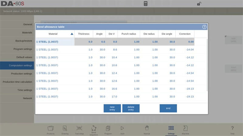
In the DELEM DA-69S Settings Mode, you can select and edit entries in the table using the Tab key, and press ENTER to save the modifications after editing. It should be noted that only loaded tables can be edited here; new tables cannot be created. For detailed information about bend allowance tables, please refer to the DELEM user manual. To load a table, click "Load Table" and select the storage location of the table file.
In addition to the bend allowance calculation method, the following computation-related parameters can also be adjusted:
1. Data Preparation Bend Allowance:
◦ Correction Off: No bend allowance is added in numerical programming.
◦ Correction On: Bend allowance correction is added in numerical programming.
◦ This setting affects the values in product programming under Program Mode, thereby influencing the axis correction data stored in the program. However, it does not affect the Drawing Mode during the controller post-processing process, as the Drawing Mode always considers the bend allowance.
1. Bottoming Force Factor: The bottoming force is calculated as "air bending force × bottoming force factor". The bottoming force can be controlled by adjusting this factor.
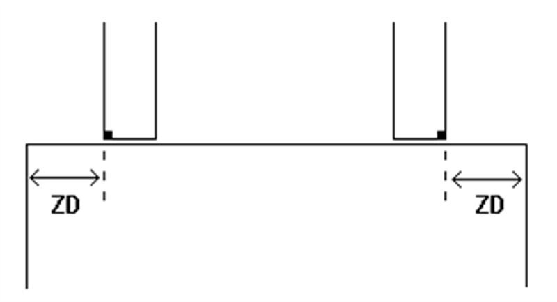
2. Z-Distance: Defines the distance from the edge of the finger to the corner of the sheet. For systems equipped with an automatic Z-axis, the finger position is automatically calculated based on the end of the sheet.
Step 8: Fine-Tuning Production Settings
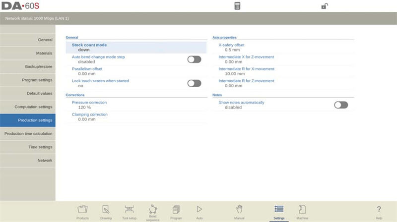
In the "Production Settings" tab, you can fine-tune the production process through the following parameters to ensure operational safety and precision:
• Stock Count Mode:
◦ Down Counting: The stock counter decreases by 1 for each completed product cycle; the device stops running when the counter reaches zero, and the counter resets when started next time.
◦ Up Counting: The stock counter increases by 1 for each completed product cycle, which is suitable for production progress statistics.
• Auto Bend Change Mode Step:
◦ Disabled: The next set of bending parameters must be selected and started manually.
◦ Enabled: The system automatically loads the next set of bending parameters, but the start button must be pressed manually to trigger the axis positioning action.
• Parallelism Offset: The overall parallelism of the Y-axis stroke can be set to ensure that the Y-axis parallelism remains within the allowable range during production.
• Lock Touch Screen When Started: You can choose to lock the touch screen during device operation to prevent parameter changes caused by misoperation.
• Pressure Correction: The percentage of the calculated force can be adjusted to achieve precise control of the pressure valve.
• Clamping Correction: The beam position can be offset to achieve firm clamping of the sheet. Entering a positive value deepens the beam position, while entering a negative value raises the beam position.
• Default Part Support Return Speed: If the device is equipped with a part support function, the return speed of the part support after bending can be set (expressed as a percentage of the maximum speed).
• X-Safety Offset: Defines the minimum safety zone of the X-axis to prevent collisions between the R-axis and machine components during operation.
Intermediate X for Z-Movement
This parameter is a key setting in the DELEM DA-69S to prevent collisions during Z-axis movement. It defines a standard X-axis safety zone applicable to all programs. The specific description is as follows:
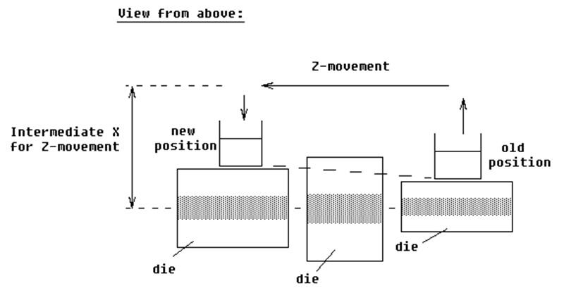
1. Purpose: Sets a temporary X-axis safety value to avoid collisions (especially for dies of different sizes). Note that this should not be confused with the "X-Safety Offset".
2. Functional Logic:
◦ If the value is 0, this function is disabled.
◦ When enabled, it ensures a consistent safety zone for the X-axis.
1. Usage in Die Operations: The intermediate X-value needs to be set to a value larger than the safety zone of the largest die to ensure sufficient clearance.
2. Movement Scenarios and Action Logic:
◦ Both the old and new X-axis positions are outside the safety zone: The X-axis and Z-axis move simultaneously.
◦ The old X-axis position is outside the safety zone, and the new X-axis position is inside: The Z-axis moves first, followed by the X-axis.
◦ The old X-axis position is inside the safety zone, and the new X-axis position is outside: The X-axis moves first, followed by the Z-axis.
◦ Both the old and new X-axis positions are inside the safety zone: The backgauge first moves to the intermediate X-position, then the Z-axis moves, and finally the X-axis moves to the new position.
Intermediate R for X-Movement
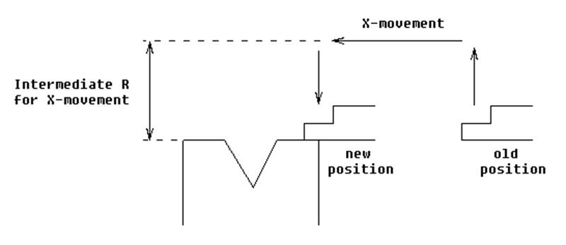
1. Purpose: Prevents collisions during X-axis movement by temporarily adjusting the R-axis position.
2. Functional Logic:
◦ If the value is 0, this function is disabled.
◦ If the value is non-zero, this function is automatically activated when the X-axis enters the die's safety zone.
1. Action Process:
a. The R-axis moves to the intermediate position.
b. The X-axis moves to the target position.
c. The R-axis returns to its original position.
2. Safety Zone Definition:
◦ Safety Zone (SZ) = X-Safety Offset + Safety Distance (SD).
◦ Among them, the "X-Safety Offset" is the specified safety zone of the die, and the "Safety Distance (SD)" is set by the machine supplier.
Intermediate R for Z-Movement
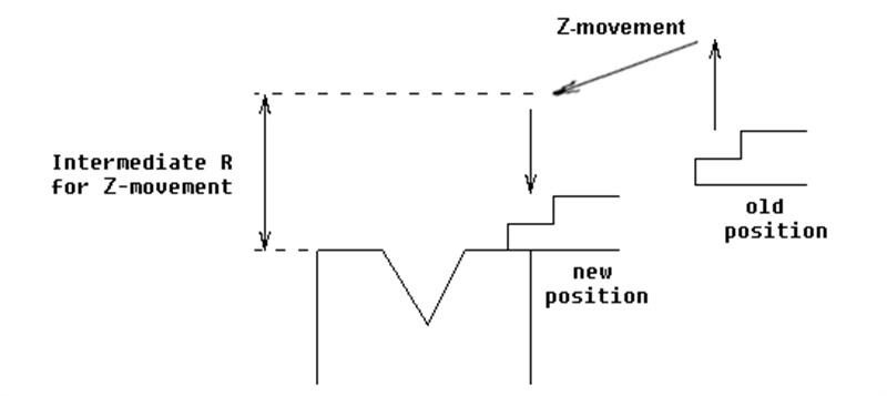
If the value of this parameter is non-zero, the system will set a temporary R-axis position. When the backgauge finger is within the die's safety zone, this setting can ensure the safety of Z-axis movement. You can adjust this parameter according to actual needs to optimize device performance and improve operational safety.
Action Process:
1. The R-axis moves to the intermediate position.
2. The Z-axis moves to the target position.
3. The R-axis returns to its original position.
In addition, in the DELEM DA-69S Settings Mode, you can configure the function of "automatically displaying bending step notes when Automatic Mode is started and a new bending step is selected". After enabling this parameter, step notes will pop up in Automatic Mode.
Step 9: Configuring Network and Time Settings
Production Time Calculation
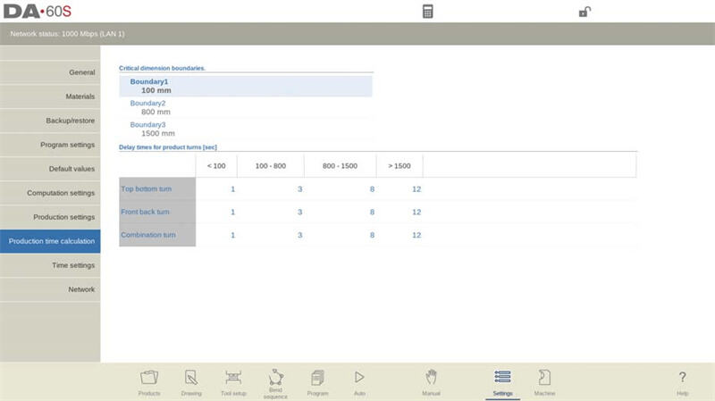
In the DELEM DA-69S Settings Mode, you can optimize the production time calculation function for the bending process. Production time is mainly affected by two factors: one is the positioning speed of the axes (depending on machine settings), and the other is the product handling time (depending on product dimensions).
The product handling time varies with dimensions: Products with small dimensions in the Z-axis direction can be flipped quickly, while products with large dimensions in the X-axis direction (requiring front-to-back flipping or combined flipping) require longer handling time. The handling time can be adjusted in the following ways:
• Set 3 boundary values to divide the product length into 4 intervals.
• Set the flipping time (in seconds) for each interval individually.
Time Settings
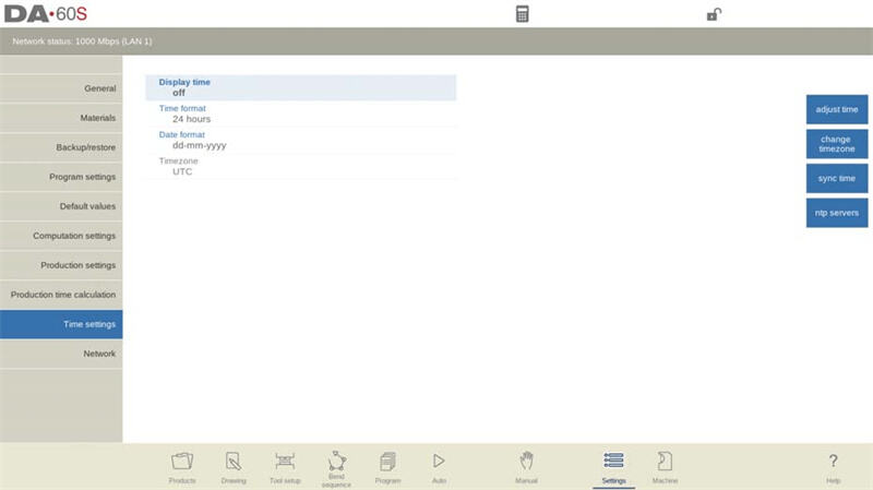
• Display Time: You can set the time display mode of the title bar, with options including "Display Date and Time", "Display Time Only", or "No Time Display".
• Time Format: You can choose to display the time in 24-hour format or 12-hour format.
• Date Format: You can choose the display format of the date, with options including "dd-mm-yyyy", "mm-dd-yyyy", or "yyyy-mm-dd".
• Adjust Time: You can manually modify the date and time, and after modification, the date and time of the system operating system will also be updated synchronously.
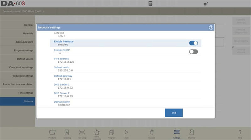
Network Settings
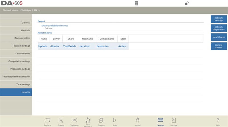
In the "Settings" Mode of the DELEM DA-69S, you can access the "Network" tab through the "Network" option. This tab includes network settings, diagnostics, local sharing, and remote sharing functions, which can improve the connectivity of the device.
• Network Parameter Configuration: With the assistance of the system administrator, set standard network parameters (to ensure normal network connection).
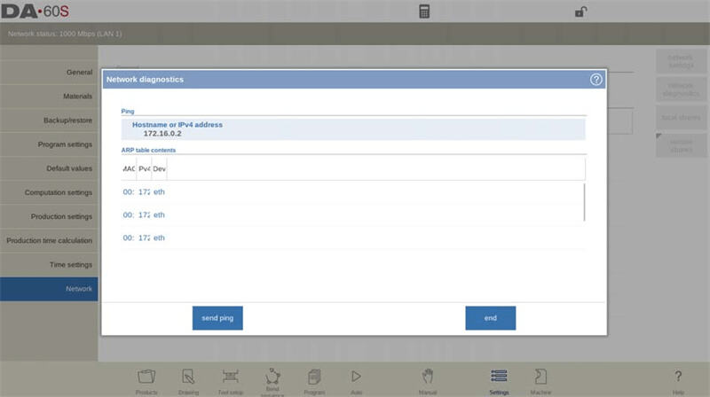
• Network Diagnostics: Basic network data transmission diagnostic tools are provided, which can be used to check whether the network function is normal.
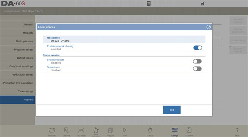
• Local Sharing: Relevant settings can be enabled to share the local directory of the CNC to the network for access by other devices.
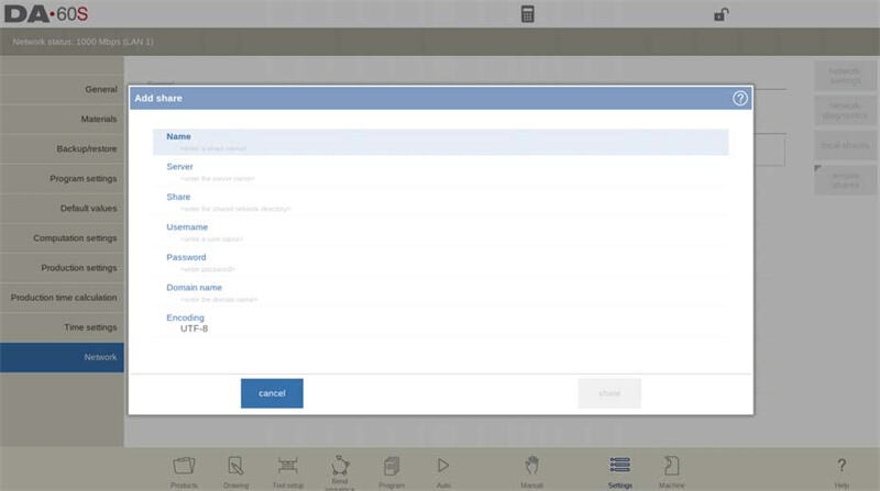
• Remote Sharing: Remote directories can be shared in the network and accessed from the CNC side. Shared directories can be added or deleted according to needs to improve operational efficiency.
Frequently Asked Questions (FAQ)
Can I customize parameters in the DELEM DA-69S Settings Mode?
Yes. The DELEM DA-69S Settings Mode supports the customization of various parameters, such as stroke length and backgauge configuration. These parameters can be adjusted according to actual production needs to optimize device performance.
Does the DELEM DA-69S Settings Mode have a reset function?
Yes. In the DELEM DA-69S Settings Mode, access the "System Settings" tab to find the "Restore Default Settings" option. If you encounter configuration issues or want to restore all parameters to their initial state, you can use this function.
What should I do if the DELEM DA-69S Settings Mode is unresponsive?
If the Settings Mode is unresponsive, you can troubleshoot according to the following steps:
1. Check whether all connections (such as power supply and data cables) are secure.
2. Restart the machine and then try to enter the Settings Mode again.
3. If the problem is still not resolved, you can refer to the troubleshooting chapter in the user manual or contact official technical support for assistance.
Conclusion
Configuring the DELEM DA-69S Settings Mode requires following a number of key steps to ensure the device achieves optimal performance. Through the guidelines introduced in this article (such as parameter configuration and regular checks), operational errors can be effectively reduced and overall production efficiency can be improved.
If you need further support during the use of the DELEM DA-69S or have specific questions to consult, please feel free to contact our team; we will provide detailed technical assistance to ensure you have all the resources needed for the efficient operation of the device. In addition, you can also refer to our other documents to obtain more device usage tips and in-depth analysis, helping you fully tap the value of the device.

