


Key Concepts of Sheet Metal Bending
In sheet metal bending, several design concepts must be considered in relation to the final part dimensions. Before exploring these key ideas, it is helpful to understand some fundamental terms:
Neutral Axis: An imaginary line within the metal that neither stretches nor compresses during bending.
Tension Zone: The region on the outside of the bend where the material is stretched.
Compression Zone: The region on the inside of the bend where the material is compressed.
Bend Line: The straight or curved line along which the bend occurs.
Flange Length: The length of the flat section extending from the bend line.
The main design and manufacturing concepts are explained below.
Bend Radius
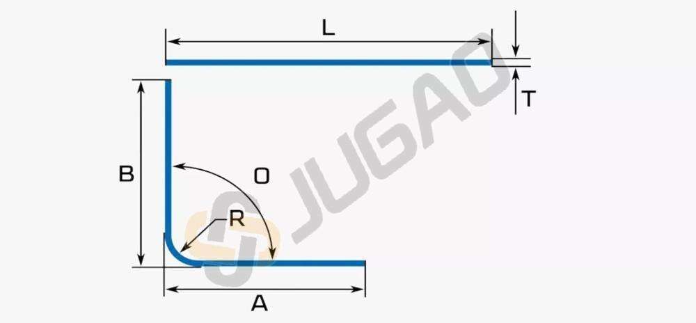
The bend radius is the inner radius of curvature formed when bending the sheet. This is a primary design variable, affecting dimensional accuracy, strength, shape, and structural integrity.
Each material and thickness has a minimum bend radius—a limit below which bending becomes impossible without causing damage. As a general rule, the minimum bend radius should be at least equal to the material thickness.
Minimum Bend Radius (Rmin) = Material Thickness (t)
Bend Deduction
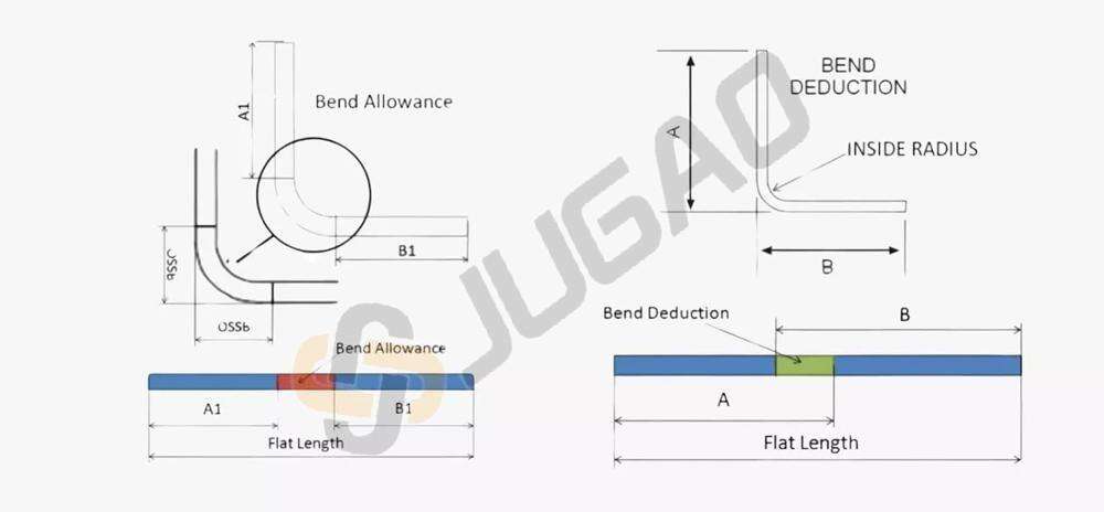
During bending, the material in the bend region stretches, causing the total flat length of the part to be slightly shorter than the sum of its flanges. Bend deduction is the amount that must be subtracted from the total unfolded length to achieve the desired final dimensions after bending.
Bend Deduction = 2 × (Outside Setback – Bend Allowance)
Accurately accounting for bend deduction is essential for achieving correct part length and specifications. The deduction value depends on material type, thickness, and bend radius.
Bend Allowance
Bend allowance is the length of the material required to form the curved portion of the bend along the neutral axis. When a sheet is bent, the inside compresses and the outside stretches, but the neutral axis remains at a constant length.
The bend allowance accounts for material thickness, bend angle, bending method, and the K-factor. It represents the arc length of the neutral axis between the two flanges.
K-Factor
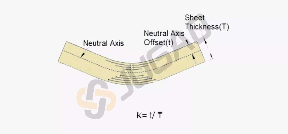
The K-factor is a key parameter in sheet metal design, defined as the ratio of the neutral axis offset to the material thickness. It typically ranges from 0 to 1 (commonly 0.25 to 0.5 in practice). For example, a K-factor of 0.3 means the neutral axis is located at 30% of the thickness from the inside bend surface.
The K-factor helps estimate how much the material stretches or compresses and is used to calculate the bend allowance. Recommended values vary based on material and bend radius.
Bend Relief
A bend relief is a small notch or cut made at the end of a bend line to prevent tearing or deformation of the material. It is essential for maintaining structural integrity and dimensional accuracy, especially when a bend does not extend across the entire part.
Bend reliefs are not needed for bends that run fully from one edge to another. They are used when the bend stops inside the sheet, to avoid stress concentration.
Design rule:
Minimum relief width ≥ Material Thickness (t)
Minimum relief depth ≥ t + Bend Radius (R) + 0.5 mm
A related concept is corner relief, which is a cut made at intersecting bend lines to allow clean corners and prevent cracking.
Springback
After bending force is released, the metal tends to partially return to its original shape due to elastic recovery—this is known as springback. It affects the final bend angle and radius, so designs must compensate for it to achieve accuracy.
Springback depends on the material's elastic properties, bend radius, and bending method. Materials with higher yield strength exhibit more springback.
Bend Sequence
The bend sequence is the order in which multiple bends are formed on a single sheet. A well-planned sequence avoids tool interference, part deformation, and handling issues. Generally, bends are made from the outside inward, and simpler or larger bends are formed before more complex ones. The sequence must also align with the available tooling and machine capabilities.
Grain Direction
Metals have a crystalline grain structure resulting from their manufacturing process (e.g., rolling). The orientation of these grains affects bendability.
To reduce the risk of cracking, especially with tight bends or certain materials, the bend line should be oriented perpendicular to the grain direction. Bending parallel to the grain increases the likelihood of fractures.

