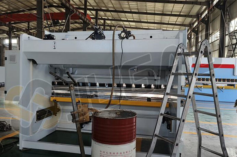
CNC Press Brake with T8 CNC Controller: Installation and Operation Guide
1. Hydraulic Oil Filling
Oil Selection: Use anti-wear hydraulic oil suitable for ambient temperatures. For standard conditions, 46# anti-wear hydraulic oil is recommended.
Oil Volume: Fill the tank to 80%-90% capacity.
Key Steps:
0:31: Connect the foot pedal switch by aligning the aviation connector’s bayonet and tightening its nuts.
0:53: Connect the power cable based on the machine’s total power. Attach the three-phase wires to the electrical cabinet’s power switch.
1:37: Turn on the electrical cabinet’s power switch.
1:57: Verify all emergency stop buttons are released.
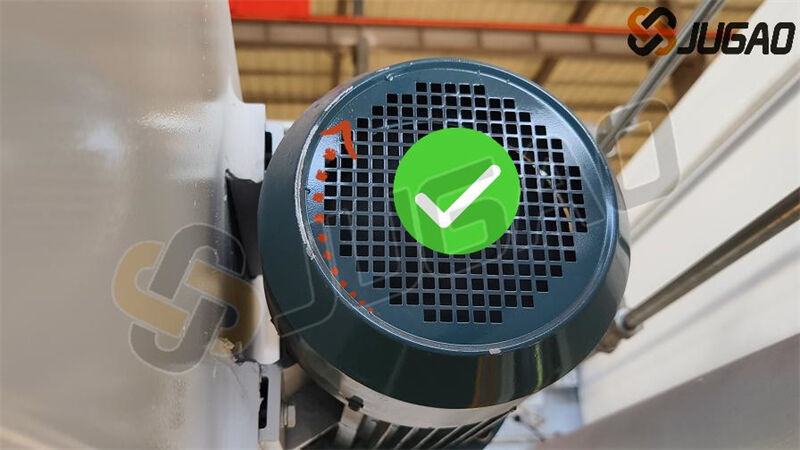
2:07: Start the oil pump via the screen button, then press the emergency stop. Confirm the main motor rotates clockwise (check the motor’s direction sticker).
○ If counterclockwise, swap two phase wires and retest.
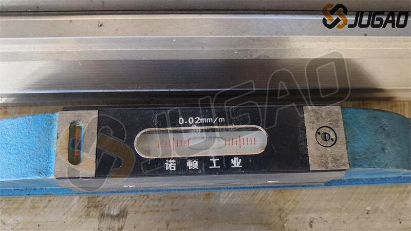
2. Machine Leveling
3:13: Use a spirit level to measure the worktable’s horizontal accuracy. Adjust the base plate bolts (place steel plates underneath for stability).
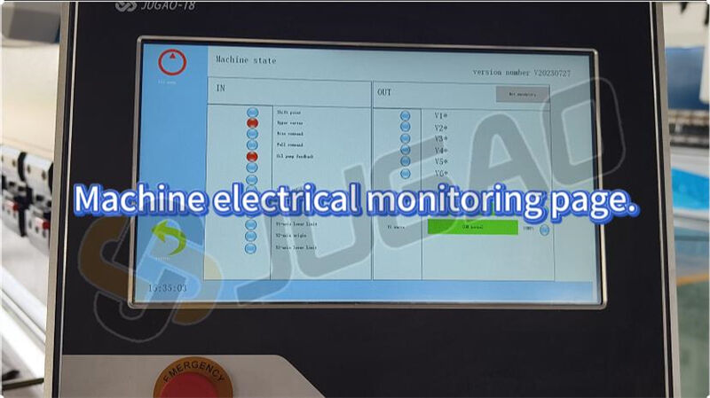
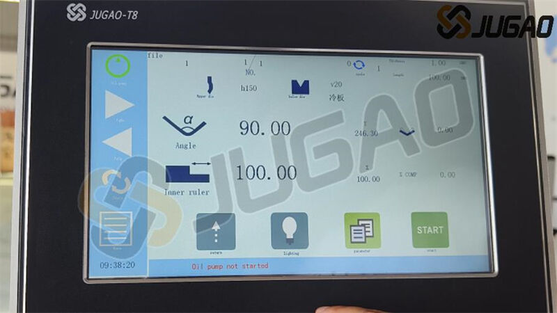
3. T8 System Interface Functions
3:37: Oil Pump Control: Hold for 3 seconds to start/stop the motor.
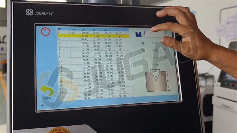
3:43: Upper Die Selection/Editing: Match the library to actual tools.
3:48: Lower Die V-Groove Editing: Input actual groove sizes (e.g., 8× sheet thickness).
3:55: Material Thickness/Length Input: Enter measured values.
4:03: Angle Display Toggle: Switch between bend angle and Y-axis value.
4:07: Bend Angle Setting: Input desired angle (e.g., 90°).
4:12: Angle Correction: Compensate deviations (e.g., enter –1.5° for a 91.5° result).
4:19: X-Axis (Backgauge) Control: Set positions for internal/external dimensions.
4:30: Slider Return: Move to upper dead center.
4:38: Program Execution: Press "START"; displays "STOP" during operation, "OK" when complete.
4:48: Pressure Delay: Set to 3.0–5.0 sec for optimal bending.
Operational Modes:
1. Inch Mode: Foot pedal controls incremental movements.
2. Single Cycle: Completes full bend cycle (fast/slow descent + pressure).
3. Continuous Mode: For testing (not production).
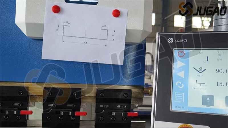
4. Tooling Setup
6:28: Upper Die Selection: Measure and input actual height.
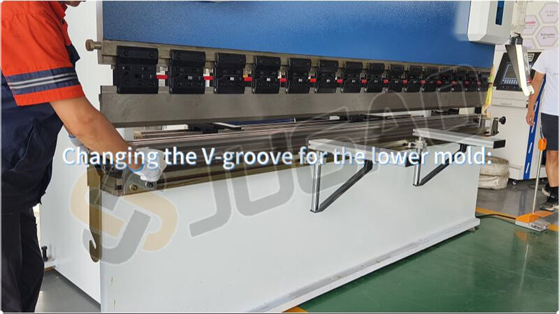
7:14: Lower Die V-Groove:
○ Rule: Groove width = 8× material thickness (e.g., 8mm for 1mm sheet).
○ Replacement: Loosen screws, flip the die, and align the new groove with the upper blade.
5. Calibration & Testing
14:15: Angle Calibration:
○ Test bend (e.g., 1mm iron plate, 90° target).
○ If error >5°: Manually adjust Y-axis (password: 0313), fine-tune in 0.5–1.0 increments.
15:52: X-Axis Calibration: Compensate measured dimensional errors.
17:47: Program Validation: Check each bend against drawings; save after alignment.
22:47: Synchronizing Left/Right Angles:
○ Adjust the sync shaft behind the slider (rotate 5 turns/test until angles match).
6. Pressure Adjustment & Alarms
26:21: System Pressure: Adjust the remote valve clockwise while pressurized.
Common Alarms:
○ Oil Pump Not Started: Press the start button.
○ Slider Not at Top: Return to upper position before operations.
○ Servo Alarm: Check for mechanical obstructions (consult JUGAO if unresolved).
Conclusion
This guide covers installation, calibration, and troubleshooting for the T8-controlled CNC press brake. For advanced support, contact JUGAO Technical Services.
Pro Tip: Always verify tooling dimensions and system settings before production runs.