


What precautions should be taken when using an electro-hydraulic press brake?
Operating an electro-hydraulic press brake requires strict adherence to safety and operational protocols to ensure both equipment integrity and operator safety. The following guidelines should be observed:
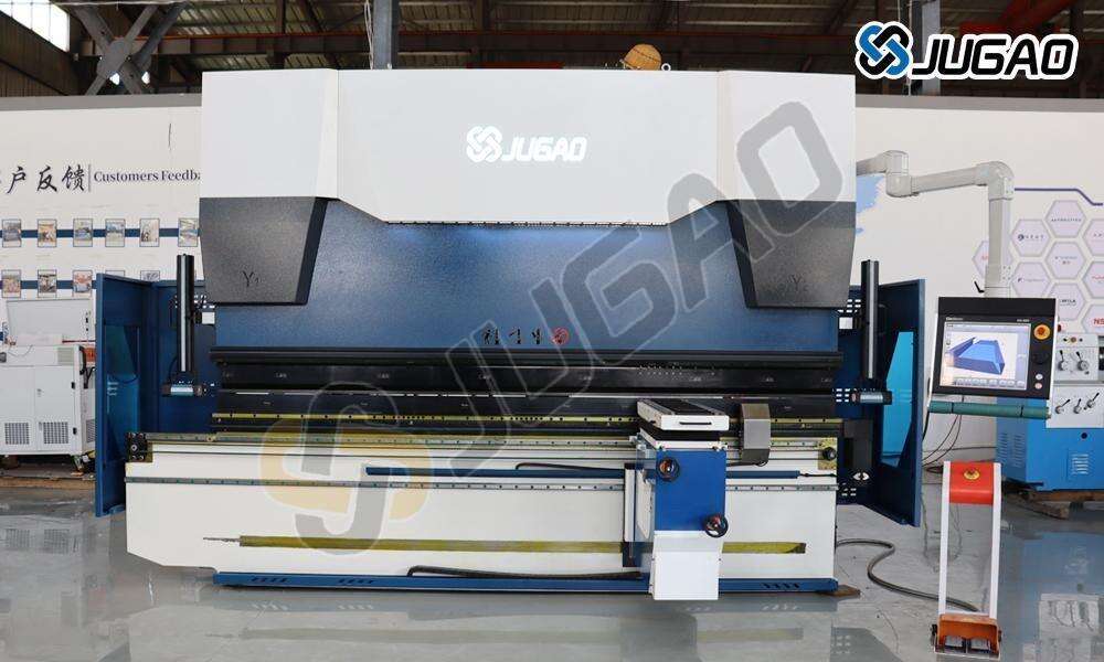
1. Machine Setup and Inspection
Ensure the base plate is firmly secured and the upper and lower blades are properly aligned and parallel. Avoid processing materials with overlapping sections or untrimmed burrs. When the machine is idle (not pressing), make sure the blades remain stable and well-balanced. Before operation, manually cycle the machine to verify all movements are normal. After a thorough inspection, release any trapped air from the hydraulic system by opening the air valve. Once operations are complete, power off the machine, ensure all valves are closed, and safely store the blades.
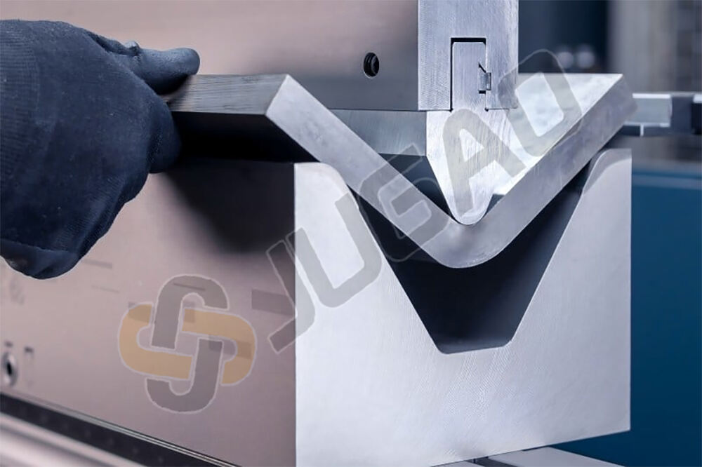
2. Stroke and Bending Preparation
When using a CNC electro-hydraulic press brake, special attention must be paid to stroke settings. Always perform a test bend prior to actual production. It is critical to maintain a material thickness clearance when the upper die reaches the bottom dead center (Z-position) to avoid damaging both the tooling and the machine. Stroke adjustment can be performed either through electric rapid adjustment or manual control. As a general rule, the V-die opening should be approximately 8 times the material thickness—for instance, a 32 mm opening is recommended for a 4 mm sheet.
3. Common Failure Causes
Startup failures are often attributed to power issues, malfunctioning positioning systems, or incorrect settings of operational controls and switches. Inconsistent or insufficient mold rigidity and fastening may also lead to operational faults. Similar issues may occur in other CNC equipment, such as shearing machines.
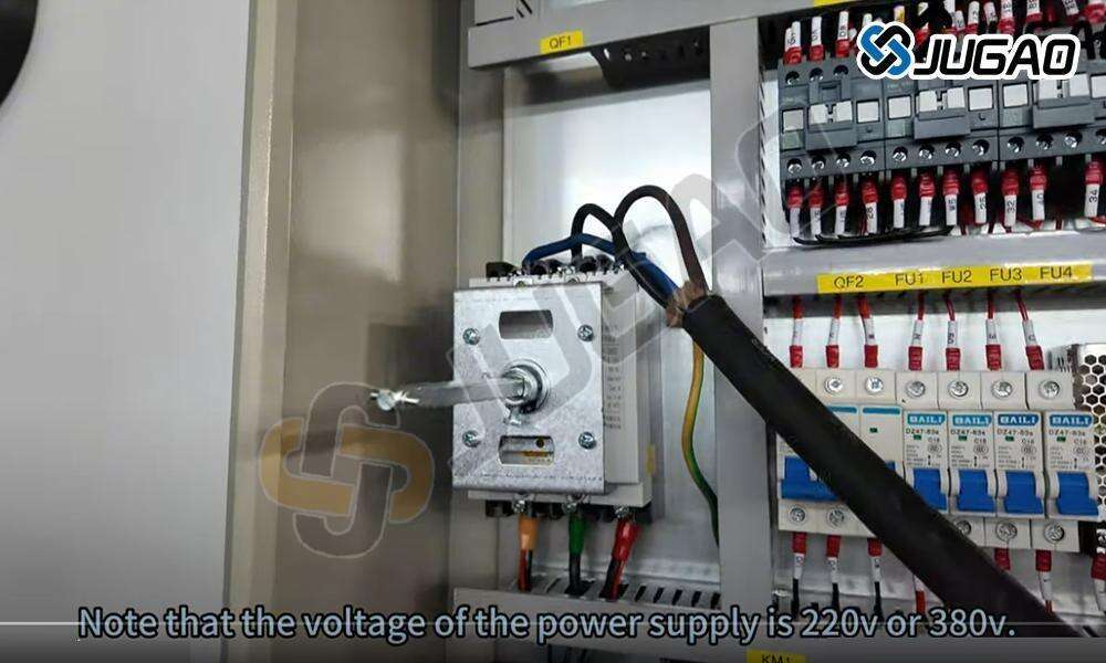
4. Electrical Checks
Before starting the electro-hydraulic CNC press brake, verify the electrical system according to standard principles:
Confirm that input power voltage matches the rating on the machine’s nameplate.
Check the output voltages of the control and servo transformers.
Ensure all circuit breakers are closed; the cooling fan in the electrical cabinet should start running.
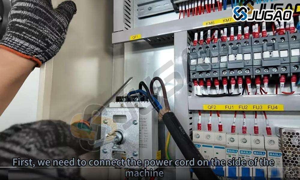
Inspect the main circuit for possible short circuits.
Only after these checks should the main power switch be turned on.
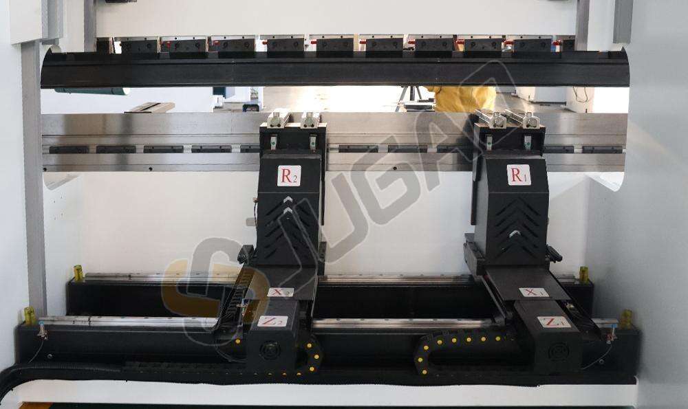
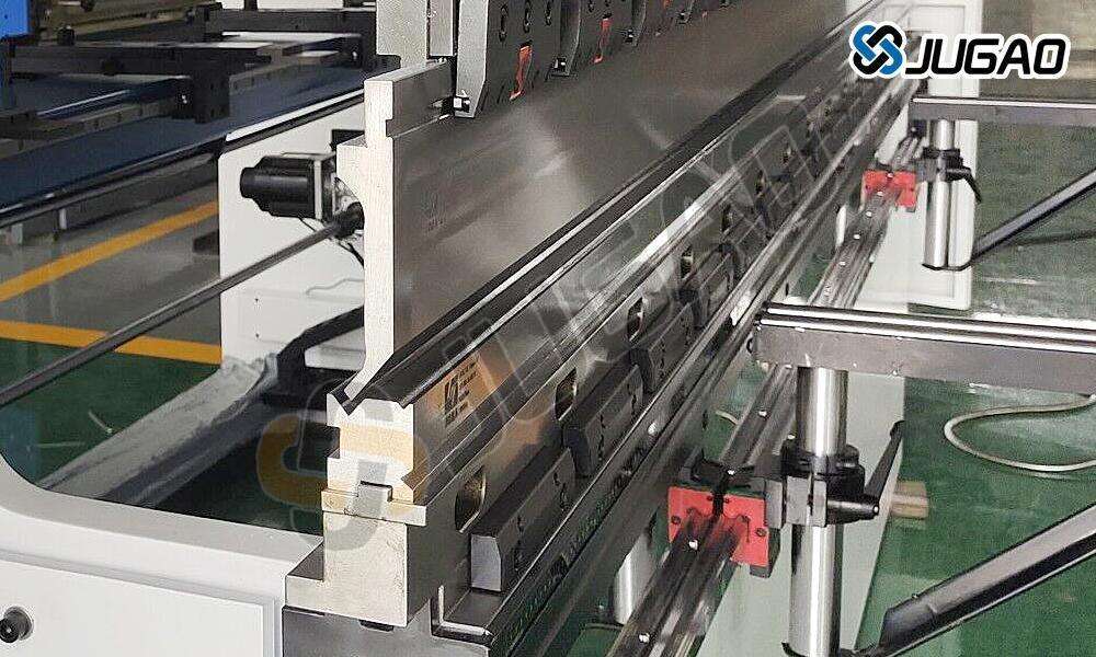
5. Die Adjustment Guidelines
The press brake is typically equipped with a customized rear die frame of standardized dimensions. The width of the lower die must correspond to the U-shaped worktable to facilitate profile-based adjustments. Note the following:
Stamping small holes can be challenging due to interference from the central front plate.
The pressure plate should be positioned close to—but not covering—the guide sleeve hole of the upper die to avoid overstroke damage.
Maintain consistent opening height and ensure the T-slot pressure plate continuously presses the upper die to prevent sudden spring release from the guide posts, which could cause rapid separation of the dies.
Uniform-length compression springs installed on the guide pillars help automatically separate the upper and lower dies after each stroke.
Implement side or rear discharge mechanisms for efficient chip removal and continuous operation.
Keep the lower die height uniform to avoid workpiece deformation caused by uneven stamping.
Use standardized components to simplify maintenance and replacement.
By following these procedures, operators can enhance operational safety, prolong machine service life, and maintain processing accuracy.

