




What are the key points to consider when installing pipe bending machine components?
The pipe bending machine industry is providing increasing technical support to the manufacturing sector. Statistics show that, based on sales distribution across manufacturing sectors, sheet metal accounts for 35%, automotive for 34%, aerospace for 12%, and others for 19%. High-quality pipe bending machine dies can also attract users. For users, cost-effective products are always the goal of purchasers, and good products can improve enterprise efficiency, meaning savings in processing costs and increased economic benefits. So, what are the key points to consider when installing pipe bending machine components?
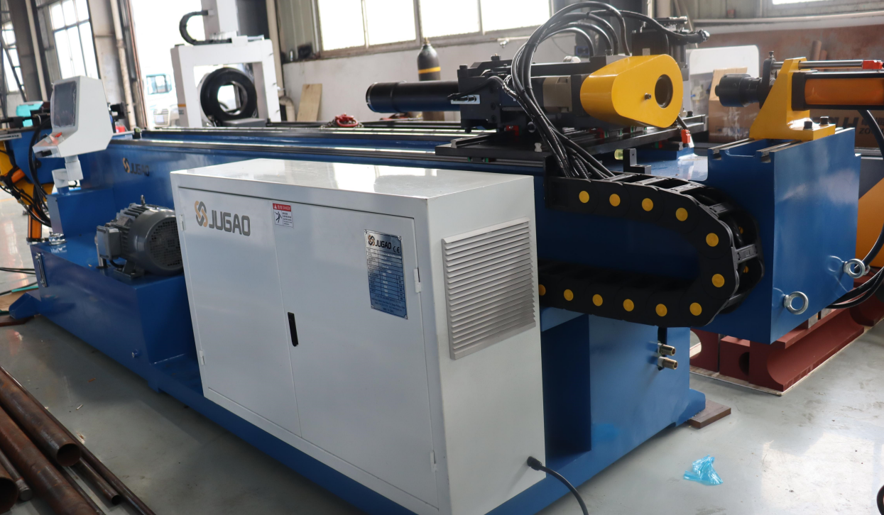
I. Pipe Bending Machine Springback Control – Springback is significant when no mandrel is used. This must be considered when selecting a bending die. Depending on the bending radius, springback can cause the pipe to return to 2 to 10 degrees, and may also increase the bending radius. The smaller the bending radius, the less springback. Springback is affected by the die position and pressure. This method allows the same bending die to produce different radii. Furthermore, the position of the mandrel can cause significant springback, reducing the bending angle and potentially increasing the radius. When the radius increases, the mandrel should be pushed (towards the tangent point). There is no ready-made formula for adjusting the mandrel setting. Obviously, when the springback angle is greater than 3 degrees, the mandrel is too far back, and the bending radius of the tube will be greater than the bending die.
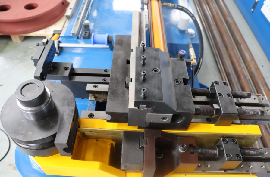
II. Mandrel Too Far Forward – A mandrel that is too far forward has several consequences. There will be a bulge at the end of the outer bend cut point, and a depression at the beginning of the inner bend cut point. These deformations are exemplified on a single tube. However, due to differences in mandrel shape and bending radius, they do not always occur simultaneously. When using an insert mandrel, the die length should be at least three times the tube diameter.
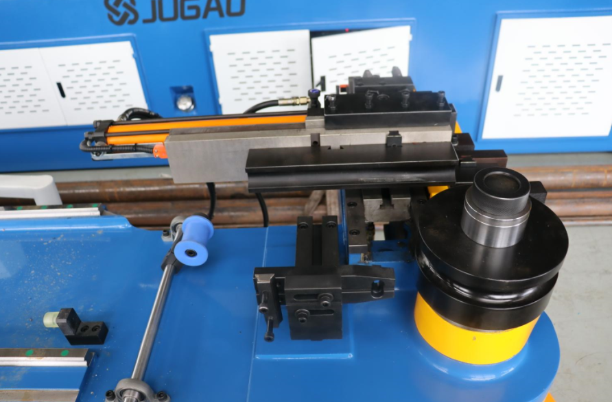
III. Mandrel Too Far Back – The mandrel is slightly forward; wrinkles do not form at the front but begin to form behind the cut point. The mandrel position is still not far enough forward to generate the necessary pressure on the inside to shrink the material. When the bent tube is removed from the bending die, there will be a large wrinkle. Therefore, it is necessary to push the mandrel further until the material is no longer squeezed between the mandrel and the bending die.
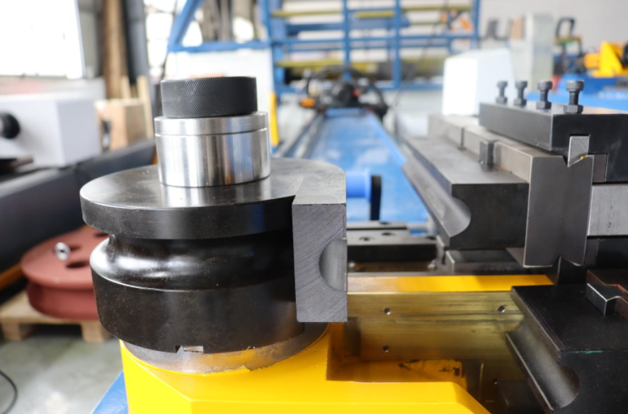
IV. Pump slippage, also known as pump overflow or return pumping, is usually caused by the oil outlet valve's steel ball failing to return to its normal position. Extend the actuating rod to apply pressure to the plunger pump, then tap the handle seat a few times with a hammer to reset the valve ball.
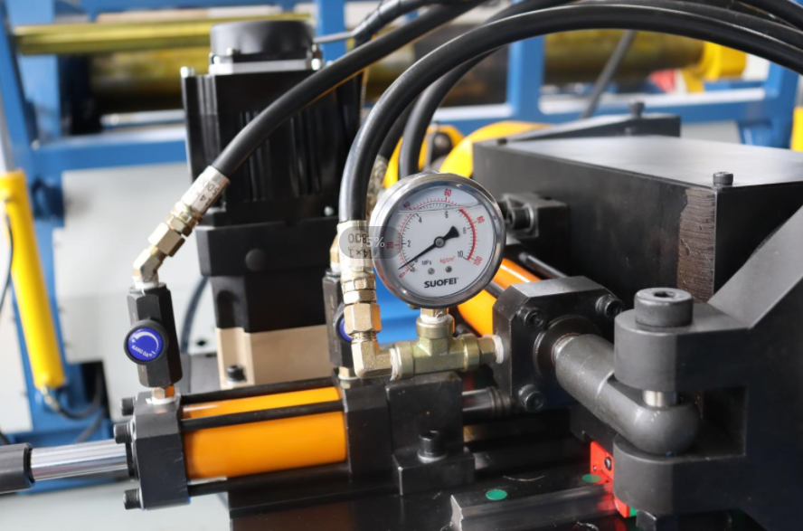
V. Insufficient oil suction from the large and small pumps is caused by debris or insufficient oil in the filter screen. Unscrew the bending die parts, clean the screen with gasoline, and refill with oil.
VI. Oil leakage at the top of the ejector rod is mainly due to a damaged piston rod top seal. Replacing the 14×2.4O type seal should resolve the issue.
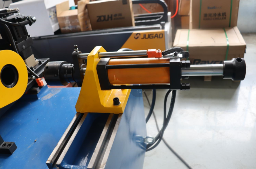
VII. Cracks in the die mounting hole are generally caused by lateral loads during die ejection, such as improper positioning when re-bending a bent workpiece. Check the symmetry of the two support rollers, apply oil to the contact area between the support rollers and the workpiece, and correct the position for the second bend.

