





Vertical Profile Bending Machine - Structural Composition
The profile bending machine features an arc-shaped, downward-adjustable structure. The upper roller is fixed, while two lower rollers move in an arc relative to the upper roller around a central axis. Its primary function is to pre-bend the ends of the profile and deform it. Simultaneously, the two lower rollers also serve as the main drive shafts, driven by hydraulic motors to roll the deformed profile into shape. To prevent twisting deformation of the profile during the bending process and improve bending accuracy, two support rollers and wheels are added, allowing for vertical up-and-down movement to accommodate profiles of different specifications and bending radii. All moving parts of the vertical profile bending machine are installed within a welded structure bed, forming the main body of the machine. All machine movements are hydraulically driven, with centralized electrical control of the lower rollers' lifting movement. Digital display and centralized operation are all located on the control panel.
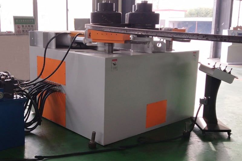
Structural Composition Overview
1. Drive Unit
The machine's three dies each have a drive device. Driven by a high-torque hydraulic motor, it can rotate in both forward and reverse directions, thus avoiding slippage during the rolling process. The linear speed of the upper and lower dies is automatically matched during rolling.
Both rotary movements are equipped with braking devices to ensure accurate positioning of the workpiece during rolling.
The device operates smoothly and rolls flexibly and reliably.
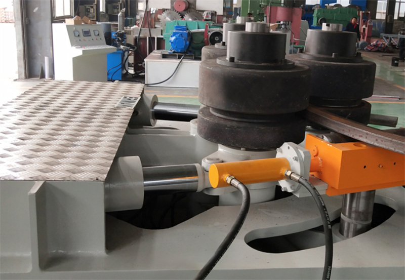
2. Spindle Section
The spindle is the main actuator of the equipment, possessing sufficient strength, rigidity, surface hardness, and machining accuracy to ensure reliability and service life during operation.
All three spindles are supported by self-aligning roller bearings. These bearings are suitable for low-speed, heavy-load applications, offering long service life and low friction loss.
The large span between the two bearings supporting the spindle increases its stability.
The upper spindle is fixed in position, while the two lower spindles are driven by double-acting hydraulic cylinders to move in an arc around the central axis.
The rotating parts, such as the cylinder pins and central shaft, are all supported by SF-1 oil-free lubricated sliding bearings. (These bearings are a three-layer composite material with a steel backing, a layer of spherical bronze powder sintered on the steel backing, a modified polyoxymethylene surface, and a wear-resistant layer filled in the pores of the copper powder after rolling.) This is a commercially available product.
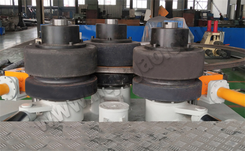
3. Die Section
The machine has three dies mounted at the ends of the three main shafts, with torque transmitted via guide keys. They are connected by central bolts, allowing for easy die replacement.
The idler rollers can move with the lower die, and can also be raised, lowered, and rotated, working in conjunction with the main die to bend profiles and provide bending accuracy.
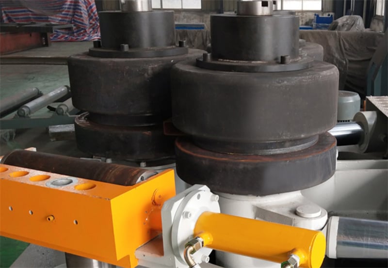
4. Hydraulic Section
The main functions of the hydraulic system are to drive the rotation of the hydraulic motor, the lifting and lowering of the two lower shafts, and the tracking of the idler rollers.
The pump station is the power source for the hydraulic system, providing the necessary power from an electric motor and pump. The control section uses a block-type hydraulic circuit to reduce piping and joints, facilitating operation and maintenance. An overflow valve and pressure relay are installed at the pump outlet for system safety protection.
When the system pressure exceeds the set pressure of the relief valve, the relief valve opens, relieving system pressure. If the relief valve malfunctions and the pressure exceeds the set pressure, preventing pressure relief, a pressure relay will provide a feedback signal to the electrical system for power-off protection.
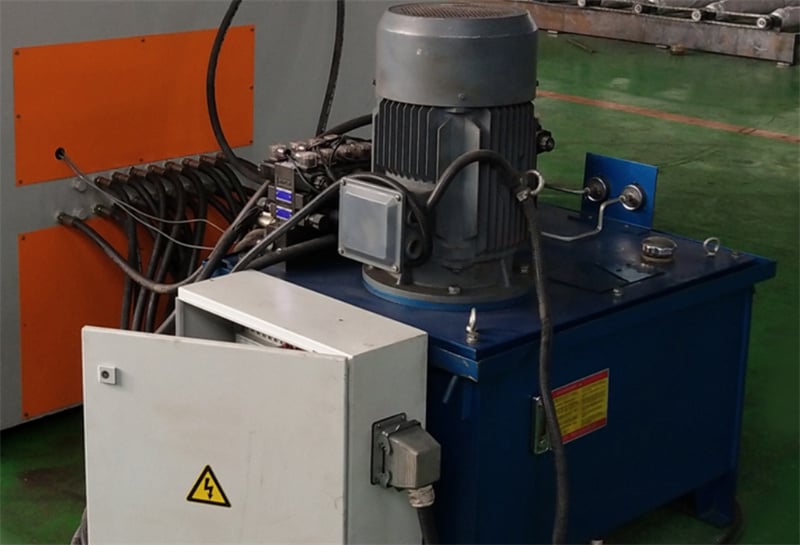
The entire hydraulic system is rationally designed and reliably operates, equipped with high-precision suction and return oil filters to ensure the cleanliness of the system oil.
An air filter ensures normal breathing and moisture evaporation in the oil tank.
An oil temperature and level gauge displays the hydraulic oil level and temperature in the tank.
The system pressure and pressure fluctuations can be visually observed through a pressure gauge.
The electro-hydraulic directional valve controls the lifting and lowering of the lower die; a hydraulic check valve allows the die to be stopped at any position.
5. Electrical System
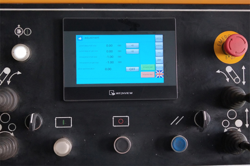
The electrical system consists of an operating console and a control system.
All actions are operated from the operating console.
Applications and Features
The vertical profile bending machine has a reasonable structure, stable performance, and significant energy and material savings, making it an ideal profile bending equipment. This equipment is a high-efficiency processing machine specifically designed for bending various special-shaped steel materials such as angle steel, channel steel, I-beams, flat steel, square steel, and round steel. It can complete the bending and straightening processes in one feeding operation. Profile bending machines are widely used in industries such as petroleum, chemical, hydropower, shipbuilding, and machinery manufacturing.

