


Sheet Metal Fabrication Technology
Sheet Metal Overview
Sheet Metal Fabrication:
Sheet metal fabrication is a comprehensive cold working process for thin metal sheets (usually below 6mm), including shearing, punching, bending, welding, riveting, die forming, and surface treatment. Its significant characteristic is that the thickness of the same part is consistent.
Sheet Metal Fabrication Methods:
1. Non-Die Fabrication: This process uses equipment such as CNC punching, laser cutting, shearing machines, bending machines, and riveting machines to process sheet metal. It is generally used for sample making or small-batch production and has a higher cost.
2. Die Fabrication: This process uses fixed dies to process sheet metal. Common dies include blanking dies and forming dies. It is mainly used for mass production and has a lower cost.
Sheet metal processing methods:
1. Non-mold processing: This process uses equipment such as CNC punching, laser cutting, shearing machines, bending machines, and riveting machines to process sheet metal. It is generally used for sample making or small-batch production and is relatively expensive.
2. Mold processing: This process uses fixed molds to process sheet metal. These typically include blanking molds and forming molds. It is mainly used for mass production and is relatively inexpensive.
Sheet metal processing flow
Blanking: CNC punching, laser cutting, shearing machine; Forming - bending, stretching, punching: bending machine, punch press, etc.
Other processing: riveting, tapping, etc.
Welding
Surface treatment: powder coating, electroplating, wire drawing, screen printing, etc.
Sheet Metal Fabrication Processes - Blanking
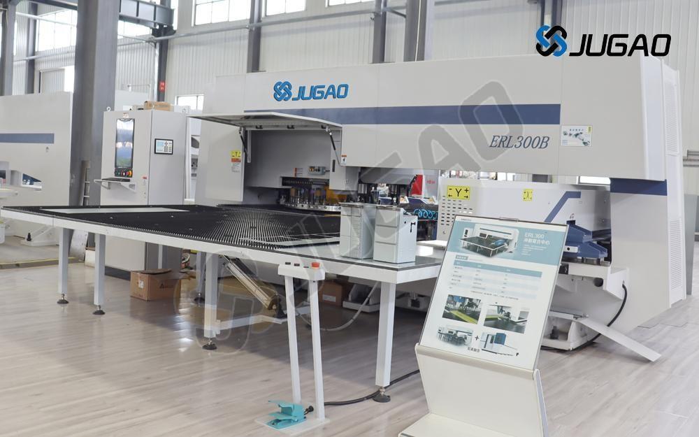
Sheet metal blanking methods mainly include CNC punching, laser cutting, shearing machines, and die blanking. CNC punching is currently the most commonly used method. Laser cutting is mostly used in the prototyping stage, but its processing cost is high. Die blanking is mostly used for mass production.
Below, we will mainly introduce sheet metal blanking using CNC punching.
CNC punching, also known as turret punching, can be used for blanking, punching holes, drawing holes, and adding ribs, etc. Its processing accuracy can reach +/-0.1mm. The sheet metal thickness that CNC punching can process is:
Cold-rolled sheet, hot-rolled sheet <3.0mm;
Aluminum sheet <4.0mm;
Stainless steel sheet <2.0mm.
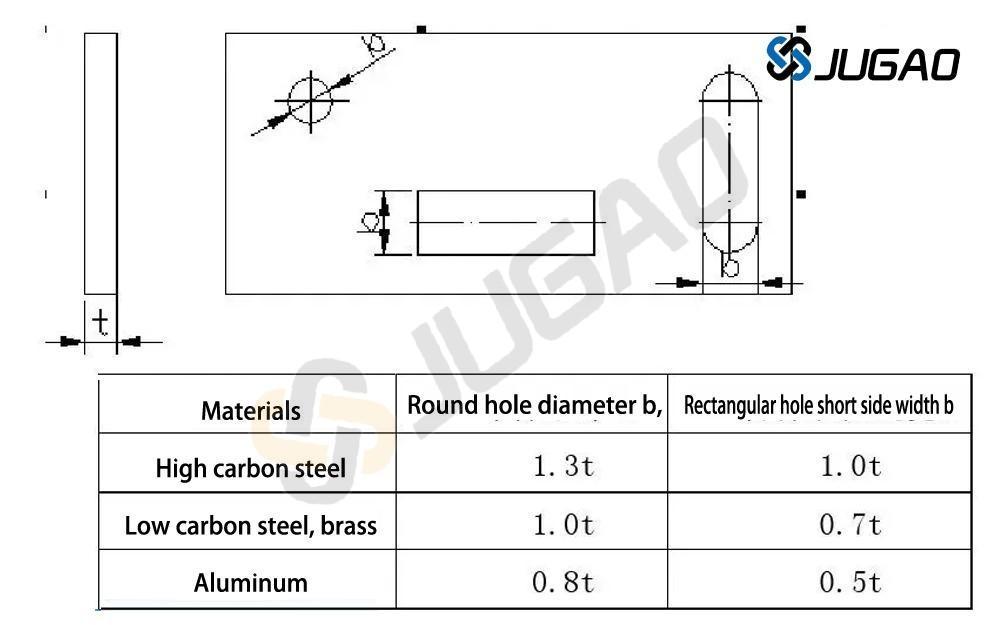
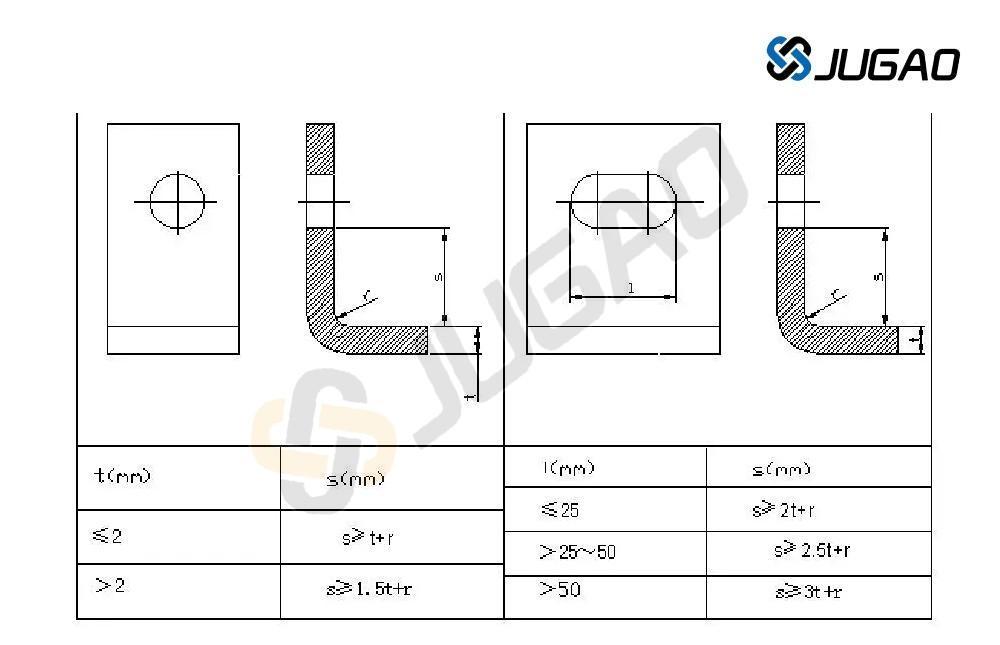
1. There are minimum size requirements for punching. The minimum punching size is related to the shape of the hole, the mechanical properties of the material, and the material thickness. (See figure below)
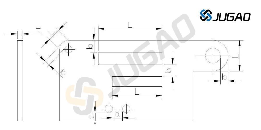
2. Hole spacing and edge distance in CNC punching. The minimum distance between the punched hole edge and the outer shape of a part is subject to certain limitations depending on the shape of the part and the hole. When the punched hole edge is not parallel to the outer edge of the part, this minimum distance should not be less than the material thickness t; when they are parallel, it should not be less than 1.5t. (See figure below)
3. When drawing holes, the minimum distance between the drawing hole and the edge is 3T, the minimum distance between two drawing holes is 6T, and the minimum safe distance between the drawing hole and the bending edge (inner) is 3T + R (T is the sheet metal thickness, R is the bending radius).
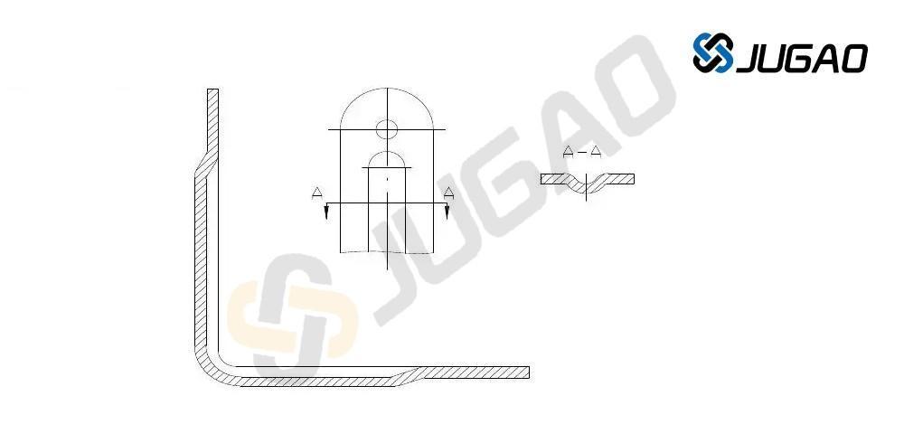
4. When punching holes in drawn, bent, and deep-drawn parts, a certain distance should be maintained between the hole wall and the straight wall. (See diagram below)
Sheet metal processing technology - forming
Sheet metal forming mainly involves bending and stretching.
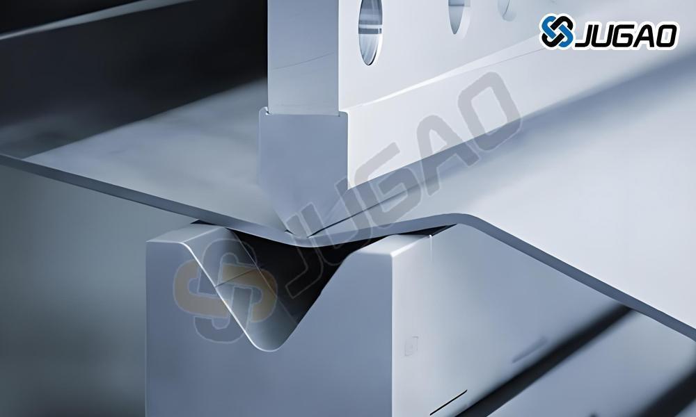
1. Sheet metal bending
1.1. Sheet metal bending primarily uses bending machines.
Bending machine processing accuracy:
First bend: +/-0.1mm
Second bend: +/-0.2mm
More than two bends: +/-0.3mm
1.2. Basic principles of bending sequence: Bending from the inside out, from small to large, bending special shapes first, then bending general shapes, ensuring that the previous process does not affect or interfere with subsequent processes.
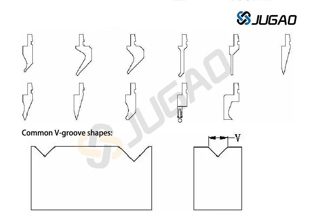
1.3. Common bending tool shapes:
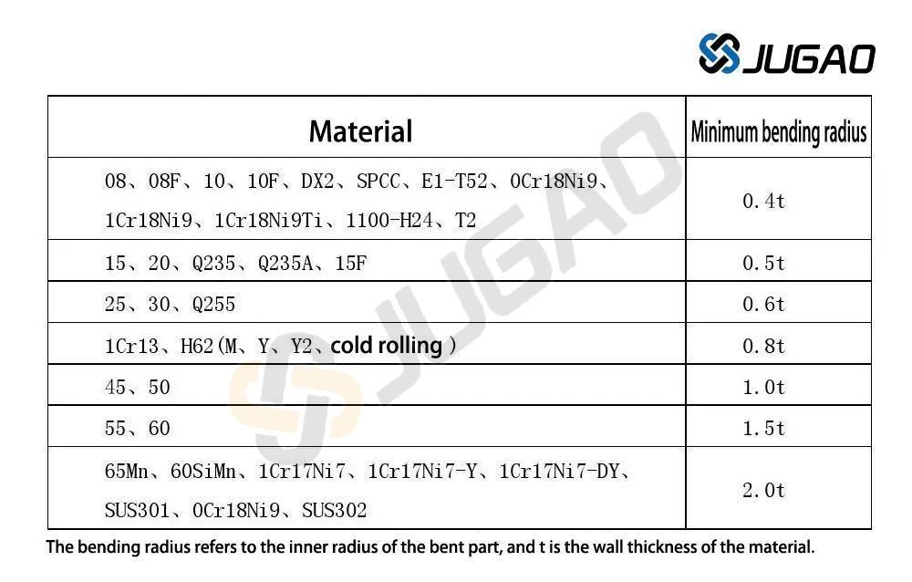
1.4. Minimum Bending Radius of Bending Parts: When a material is bent, the outer layer is stretched while the inner layer is compressed in the fillet area. When the material thickness is constant, the smaller the inner radius (r), the more severe the stretching and compression. When the tensile stress at the outer fillet exceeds the material's ultimate strength, cracks and breakage will occur. Therefore, the structural design of bent parts should avoid excessively small bending fillet radii. The minimum bending radii of commonly used materials in the company are shown in the table below.
Table of minimum bending radii for bent parts:
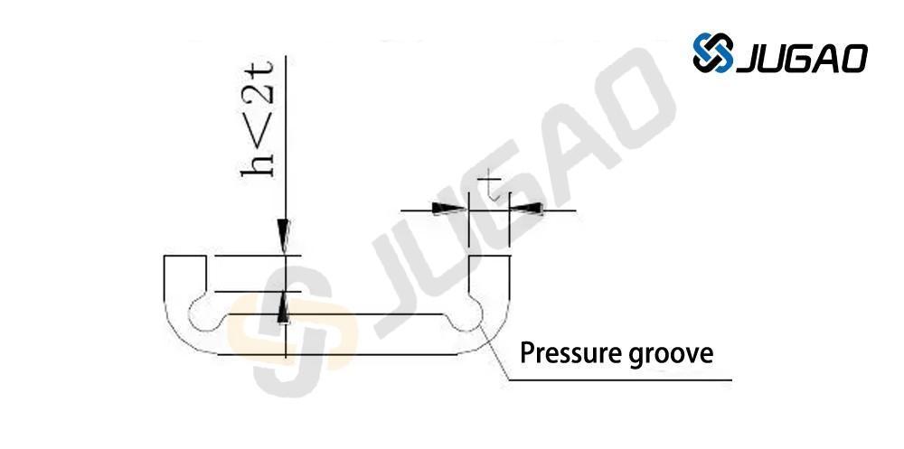
1.5. Straight Edge Height of Bending Parts Generally, the minimum straight edge height should not be too small. Minimum height requirement: h > 2t
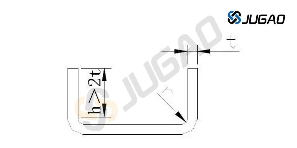
If the straight edge height h < 2t of the bent part needs to be increased first, then the bending height should be increased, and then processed to the required size after bending; or a shallow groove should be processed in the bending deformation zone before bending.
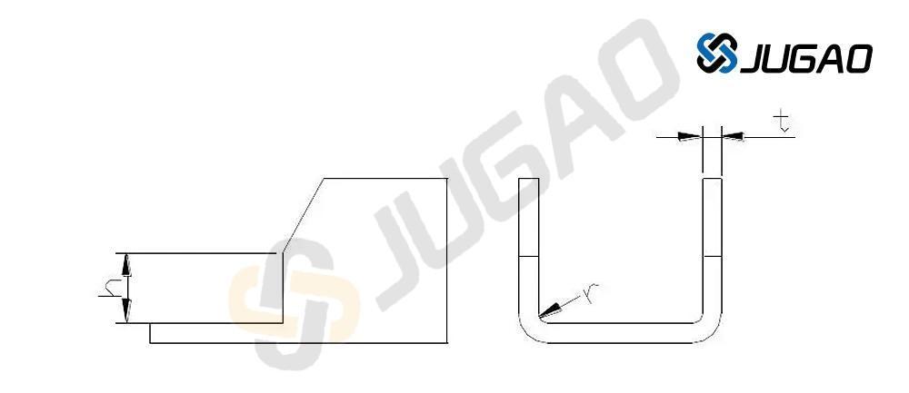
1.6. Height of a straight edge with an angled side: When a bent part has an angled side, the minimum height of the side is: h = (2~4)t > 3mm
1.7. Hole Distance on Bending Parts: Hole distance: After punching, the hole should be positioned outside the bending deformation zone to avoid deformation during bending. The distance from the hole wall to the bend edge is shown in the table below.
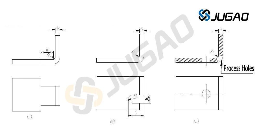
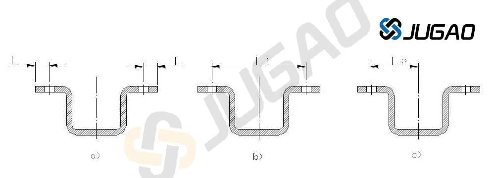
1.8. For locally bent parts, the bending line should avoid locations of abrupt dimensional changes. When partially bending a section of an edge, to prevent stress concentration and cracking at sharp corners, the bending line can be moved a certain distance away from the abrupt dimensional change (Figure a), or a process groove can be created (Figure b), or a process hole can be punched (Figure c). Note the dimensional requirements in the figures: S>R, groove width k≥t; groove depth L>t+R+k/2.
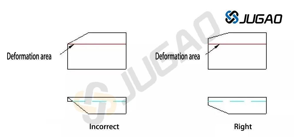
1.9. The beveled edge of a bent edge should avoid the deformation zone.
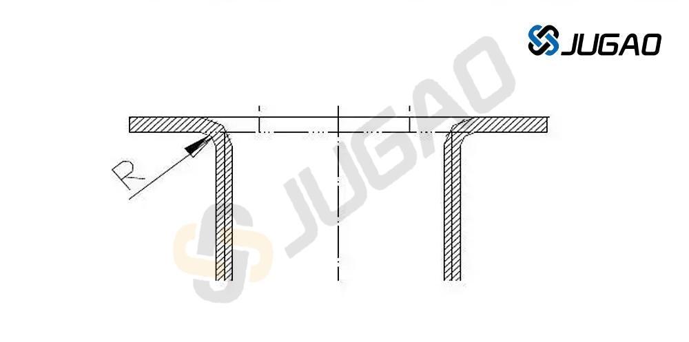
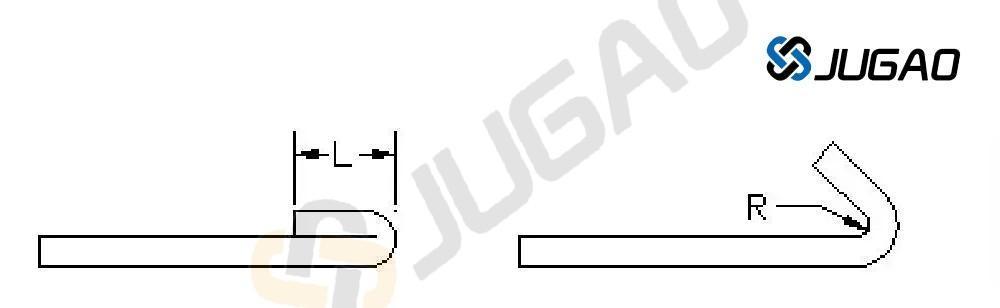
1.10. Design Requirements for Dead Edges The length of a dead edge is related to the material thickness. As shown in the figure below, the minimum dead edge length L > 3.5t + R. Where t is the material wall thickness, and R is the minimum inner bending radius of the preceding process (as shown on the right in the figure below).
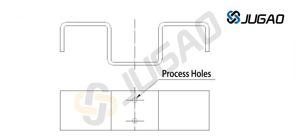
1.11. Added process positioning holes: To ensure accurate positioning of the blank in the mold and prevent blank displacement during bending, resulting in defective products, process positioning holes should be added in advance during the design, as shown in the figure below. In particular, for parts that are bent and formed multiple times, the process holes must be used as the positioning reference to reduce cumulative errors and ensure product quality.
1.12. Different dimensions result in different manufacturability:
As shown in the diagram above, a) punching the hole first and then bending it makes it easier to ensure the accuracy of the L dimension and facilitates processing. b) and c) if the accuracy of the L dimension is high, bending must be performed first and then the hole is machined, which is more complicated.
1.13. Springback of Bending Parts: Many factors influence springback, including the material's mechanical properties, wall thickness, bending radius, and normal pressure during bending.
The larger the ratio of the inner corner radius to the plate thickness of the bent part, the greater the springback.
Pressing reinforcing ribs in the bending zone not only improves the workpiece's rigidity but also helps suppress springback.
2. Sheet Metal Drawing
Sheet metal drawing is mainly accomplished by CNC punching or conventional punching, requiring various drawing punches or dies.
The shape of the drawn part should be as simple and symmetrical as possible, and drawn in one operation whenever possible.
For parts requiring multiple drawing operations, marks that may form on the surface during the drawing process should be permissible.
While ensuring assembly requirements are met, a certain degree of inclination on the drawn sidewalls should be allowed.
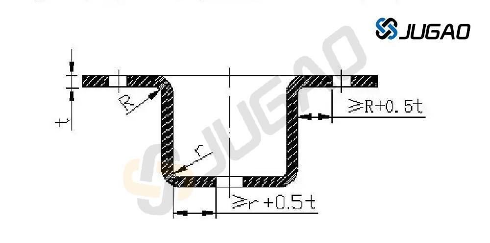
2.1. Requirements for the fillet radius between the bottom of the stretched part and the straight wall:
As shown in the figure, the fillet radius between the bottom of the stretched part and the straight wall should be greater than the plate thickness, i.e., r>t. In order to make the stretching process smoother, r1 is generally taken as (3+5)t, and the maximum fillet radius should be less than or equal to 8 times the plate thickness, i.e., r1<8t.
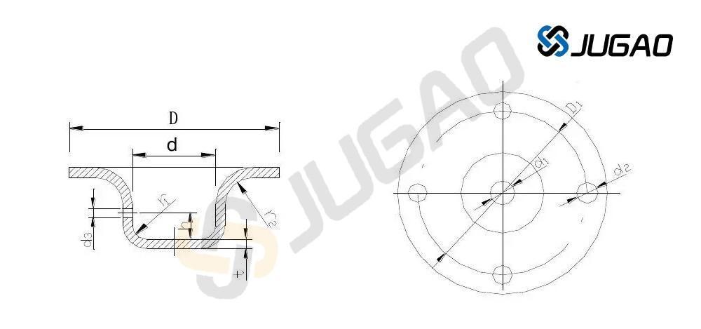
2.2. Fillet radius between the flange and the wall of the drawn part:
As shown in the figure, the fillet radius between the flange and the wall of the stretching part should be greater than twice the thickness of the plate, i.e., r2>2t. In order to make the stretching process smoother, r2 is generally taken as (5-10)t. The maximum flange radius should be less than or equal to 8 times the thickness of the plate, i.e., r2<8t.
2.3. Fillet radius between the flange and the wall of the stretching part: As shown in the figure, the fillet radius between the flange and the wall of the stretching part should be greater than twice the thickness of the plate, that is, r2>2t. In order to make the stretching process smoother, r2 is generally taken as (5-10)t. The maximum flange radius should be less than or equal to eight times the thickness of the plate, that is, r2<8t.
2.4. Inner cavity diameter of circular drawn parts: As shown in the figure, the inner cavity diameter of circular drawn parts should be D>d+10t so that the pressure plate will not wrinkle during drawing.
2.5. Fillet radius between adjacent walls of a rectangular stretching part: As shown in the figure, the fillet radius between adjacent walls of a rectangular stretching part should be r3 > 3t. In order to reduce the number of stretching operations, r3 should be greater than H/5 as much as possible so that it can be stretched out in one go.
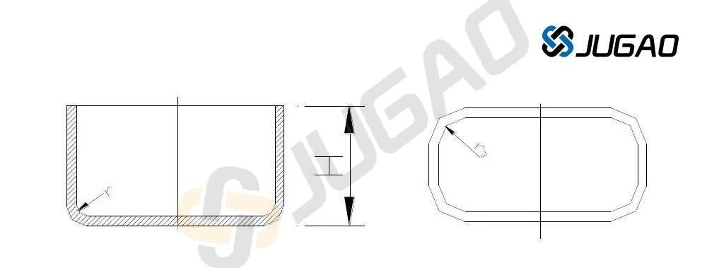
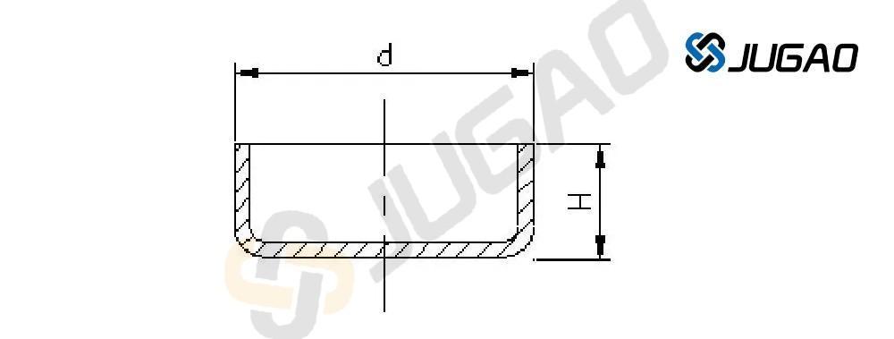
2.6. When forming a circular flangeless drawn part in one step, the dimensional relationship between its height and diameter must meet the following requirements:
As shown in the figure, when forming a circular flangeless drawn part in one step, the ratio of height H to diameter d should be less than or equal to 0.4, i.e., H/d < 0.4.
2.7. Thickness Variation of Stretched Components: Due to varying stress levels at different locations, the thickness of the material in a stretched component changes after stretching. Generally, the bottom center retains its original thickness, the material thins at the bottom rounded corners, the material thickens near the flange at the top, and the material thickens at the rounded corners of rectangular stretched components. When designing stretched products, the dimensions on the product drawing should clearly indicate whether external or internal dimensions must be guaranteed; both internal and external dimensions cannot be specified simultaneously.
3. Other Sheet Metal Forming:
Reinforcing Ribs——Ribs are pressed onto sheet metal parts to increase structural rigidity.
Louvres——Louvers are commonly used in various enclosures or housings for ventilation and heat dissipation.
Hole Flanging (Drawing Holes)——Used to machine threads or improve the rigidity of openings.
3.1. Reinforcing Ribs:
Selection of Reinforcing Rib Structure and Dimensions
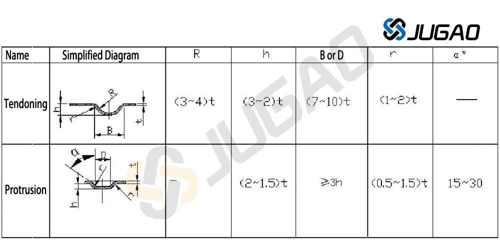
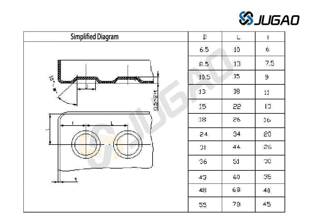
Limit dimensions of punch spacing and punch edge distance
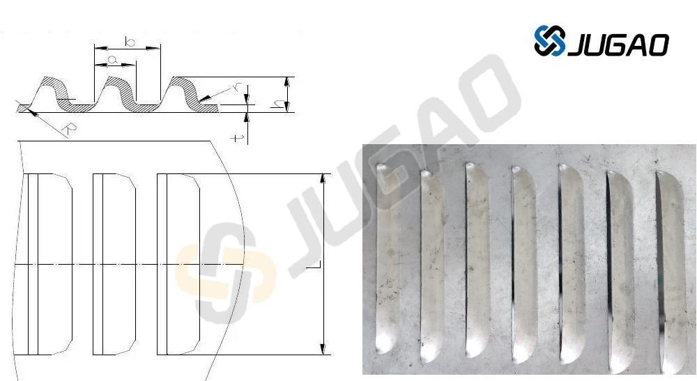
3.2. Venetian blinds:
The method of forming Venetian blinds is to use one edge of the punch to cut the material while the rest of the punch stretches and deforms the material at the same time, forming an undulating shape with one side open.
Typical structure of Venetian blinds. Venetian blind size requirements: a>4t; b>6t; h<5t; L>24t; r>0.5t.
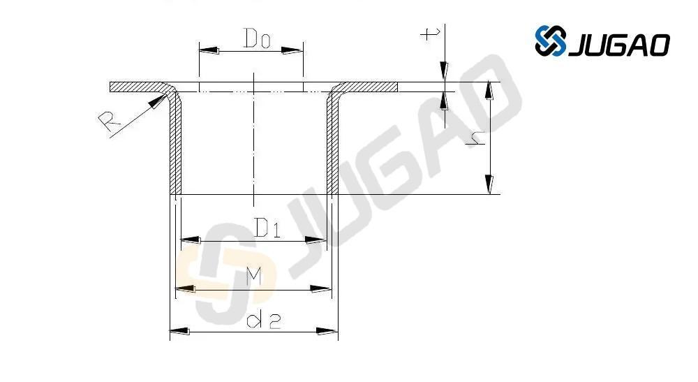
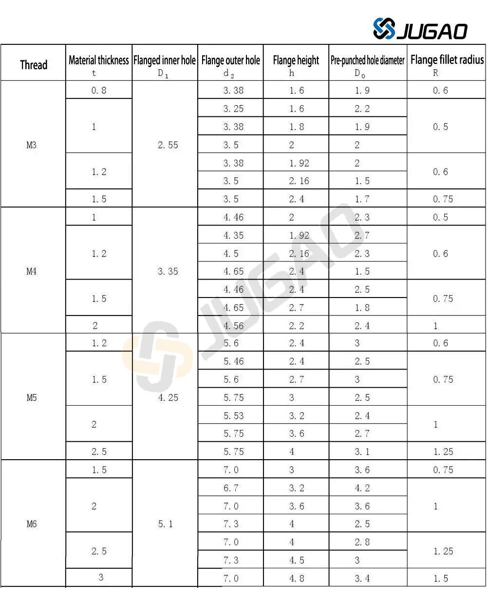
3.3. Hole Flanging (Drawing Hole):
There are many types of hole flanging, the most common being the flanging of internal holes to be threaded.
Sheet metal fabrication technology – welding
In sheet metal welding structure design, the principle of "symmetrical arrangement of welds and weld points, avoiding convergence, aggregation, and overlap" should be followed. Secondary welds and weld points can be interrupted, while major welds and weld points should be connected. Commonly used welding methods in sheet metal work include arc welding and resistance welding.
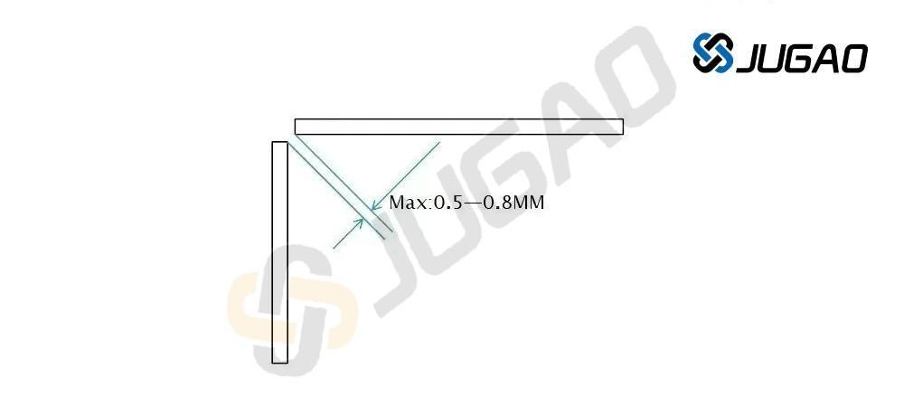
1. Arc welding:
There should be sufficient welding space between sheet metal parts. The maximum welding gap should be 0.5-0.8 mm, and the weld should be uniform and flat.
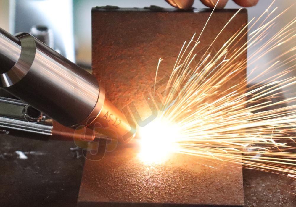
2. Resistance Welding
The welding surface must be flat and free of wrinkles, springback, etc.
The dimensions for resistance spot welding are shown in the table below:
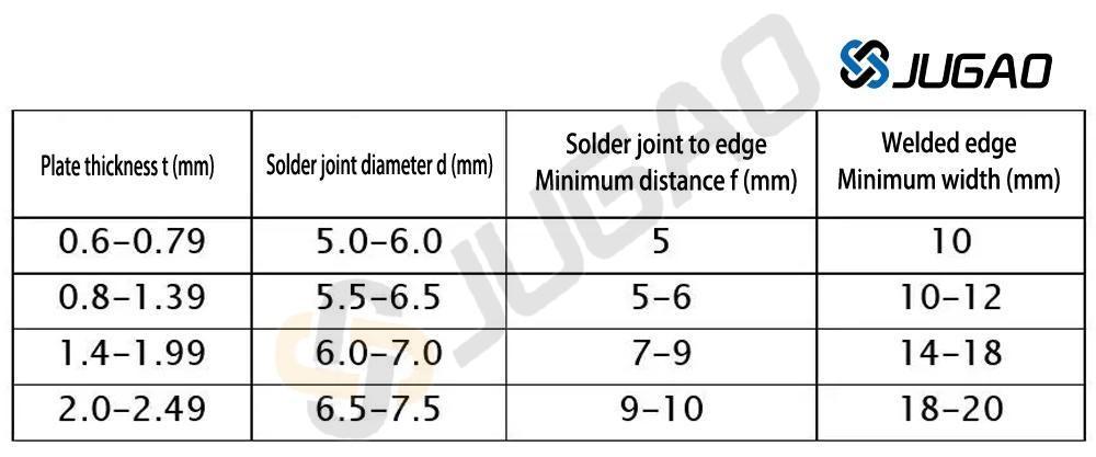
Resistance Solder Joint Spacing
In practical applications, when welding small parts, the data in the table below can be used as a reference. When welding large parts, the joint spacing can be appropriately increased, generally not less than 40-50mm. For non-load-bearing parts, the joint spacing can be increased to 70-80mm.
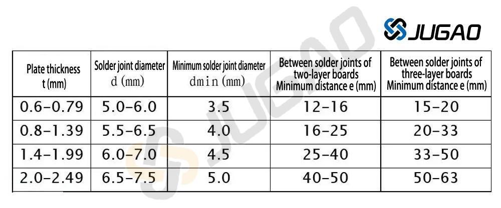
Board thickness t, solder joint diameter d, minimum solder joint diameter dmin, minimum distance between solder joints e. If the plates are of different thicknesses, select the thickness based on the thinnest plate.
Resistance Welding Plate Layer Number and Thickness Ratio
Resistance spot welding typically involves two layers of plate, with a maximum of three layers. The thickness ratio of each layer in the weld joint should be between 1/3 and 3.
If three layers are required for welding, the thickness ratio should be checked first. If it is reasonable, welding can proceed. If not, consider creating process holes or process notches, welding two layers separately, and staggering the welding points.

Sheet Metal Processing Technology - Surface Treatment
Surface treatment of sheet metal serves both anti-corrosion and decorative purposes. Common sheet metal surface treatments include: powder coating, electro-galvanizing, hot-dip galvanizing, surface oxidation, surface brushing, and screen printing. Before surface treatment, oil, rust, welding slag, etc., should be removed from the sheet metal surface.
1. Powder Coating:
There are two types of surface coating for sheet metal: liquid paint and powder paint. We commonly use powder paint. Through methods such as powder spraying, electrostatic adsorption, and high-temperature baking, a layer of paint of various colors is sprayed onto the sheet metal surface to enhance its appearance and increase the material's corrosion resistance. It is a commonly used surface treatment method.
Note: There will be some color difference between sheets coated by different manufacturers. Therefore, sheet metal of the same color produced on the same equipment should ideally be coated by the same manufacturer.
2. Electro-galvanizing and Hot-dip Zinc Die-dip Galvanizing:
Galvanizing the surface of sheet metal is a common surface anti-corrosion treatment method, and it also improves the appearance. Galvanizing can be divided into electro-galvanizing and hot-dip galvanizing.
Electro-galvanizing produces a brighter and smoother appearance, and the zinc layer is thinner, making it more commonly used.
Hot-dip galvanizing produces a thicker zinc layer and creates a zinc-iron alloy layer, which offers stronger corrosion resistance than electro-galvanizing.
3. Surface Anodizing:
This section mainly introduces the surface anodizing of aluminum and aluminum alloys.
Surface anodizing of aluminum and aluminum alloys can produce various colors, serving both a protective and decorative purpose. Simultaneously, an anodic oxide film is formed on the material's surface. This film possesses high hardness and wear resistance, as well as good electrical insulation and thermal insulation properties.
4. Surface Brushing:
The material is placed between the upper and lower rollers of the brushing machine. Abrasive belts are attached to the rollers. Driven by a motor, the material is forced through the abrasive belts, creating lines on the material's surface. The thickness of the lines varies depending on the type of abrasive belt. The main purpose is to enhance the appearance. This surface brushing treatment is generally only considered for aluminum materials.
5. Screen Printing:
Screen printing is the process of printing various markings onto the surface of materials. There are generally two methods: flatbed screen printing and pad printing. Flatbed screen printing is mainly used for flat surfaces, but pad printing is needed for deeper recesses.
Screen printing requires a screen printing mold.
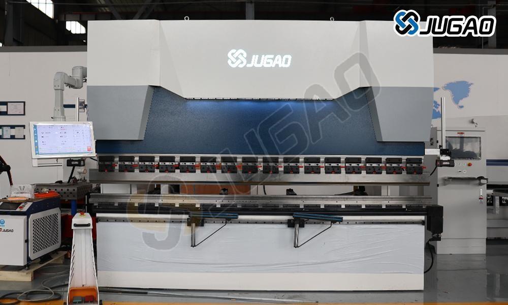
Sheet metal bending requires experience; observe how experienced craftsmen bend sheets and why they do it that way. To learn more about bending machines or bending processes, please contact our JUGAO CNC MACHINE team.

