





Safety Precautions for Different Stages of Pipe Bending Machine Operation
Fully automatic pipe bending machines are multi-step programmable and can operate automatically, greatly improving production efficiency. Because hydraulic pipe bending machines use a welded steel plate structure, stress can be eliminated during vibration. Furthermore, they use high-quality imported seals, ensuring smooth and reliable operation. Most models primarily use an upper piston press, whose driving force generation has distinct characteristics, closely related to the die manufacturing process. However, it is undeniable that pipe bending machines offer higher production safety. Safety precautions during normal use include the following:
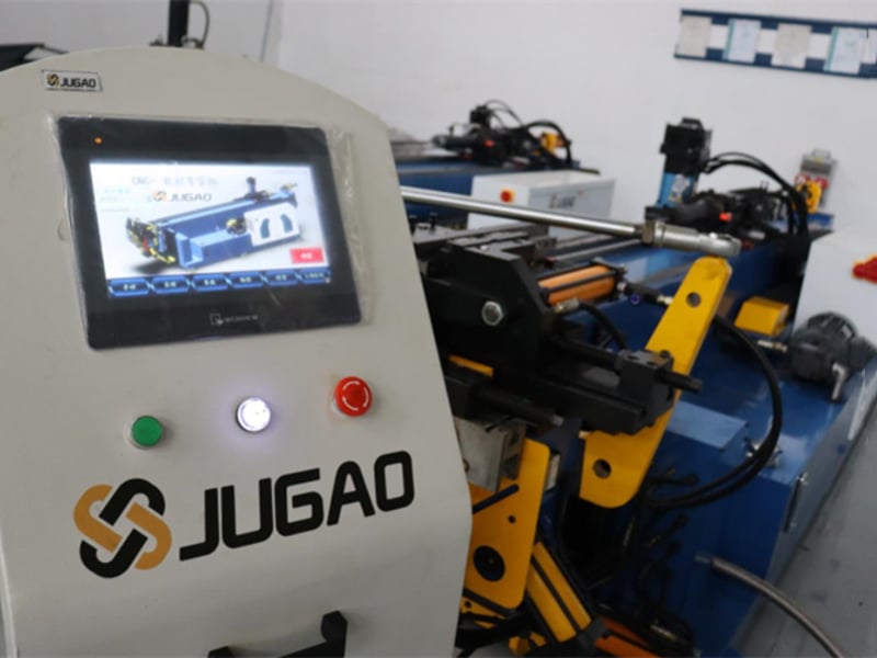
The fully automatic operation utilizes two parallel-moving hydraulic cylinders to generate pressure. This pressure is vertically downward, driving the bending beam die to perform the bending operation. The typical bending process of an upper bending beam involves several stages and steps, including downward movement, a stationary state, decompression, and return stroke:
1. Downward Movement
Ordinary downward rapid closing motion generally uses free fall, meaning movement is generated by the beam's own weight. However, the die manufacturing process differs; it utilizes a rodless chamber of a hydraulic cylinder to generate pressure, allowing for a rapid traverse speed of up to 250mm/s, making it more suitable for producing dies with higher strength.
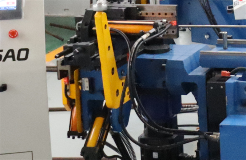
The rapid traverse begins at the top dead center and ends with a brief braking maneuver at the end, for example, bending the sheet metal a certain distance. The specific adjustment depends on the die manufacturing requirements.
2. Stationary State
In the stationary position of a fully automatic pipe bending machine, the upper bending beam is at the top dead center. This state prevents uncontrolled downward movement and reduces safety risks.
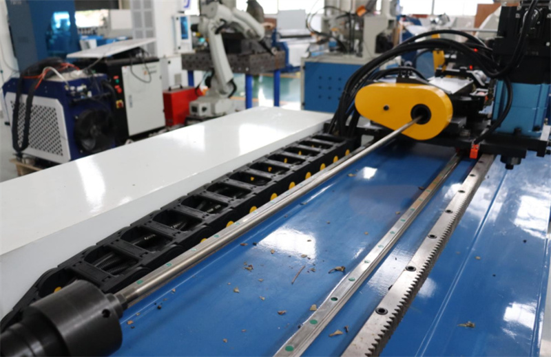
3. Decompression
Decompression of the rodless chamber, or pressure holding after reaching the bottom dead center, further improves the precision of the workpiece. Both pressure holding and decompression can be controlled by proportional directional valves. The operating cycle time is customized according to needs. When pressure reduction is required, it can be shortened as much as possible, but the pressure reduction curve should not be too steep and should be as smooth as possible.
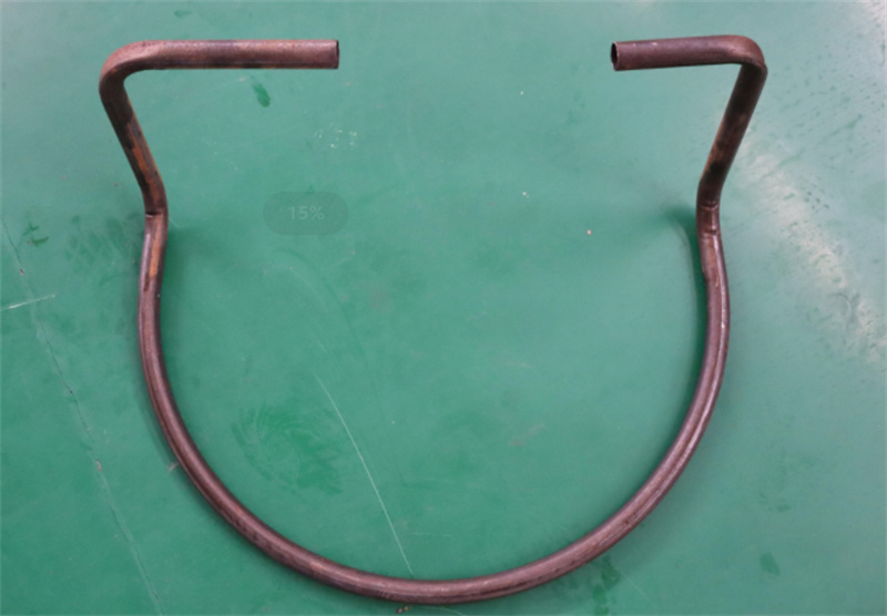
4. Return Stroke
This involves a large return speed, mainly dependent on the pump flow rate and the pressure-bearing area of the rod chamber of the hydraulic cylinder. Generally, the closer to the maximum speed, the higher the return efficiency. The return stroke must also be synchronized.

