


Professional Hydraulic Valve Group Maintenance Guide for Press Brakes
The hydraulic valve group is the core control unit of the hydraulic system.Its working state directly affects the equipment's operating efficiency andstability. Standardized maintenance can not only extend the service life of theequipment, but also prevent sudden failures and ensure production safety. Thefollowing is a professional-level maintenance operation process:
Comprehensive Maintenance Protocol
Pre-Maintenance Preparation
1. Safety Lockout Procedure
Engage main power disconnect
Install physical lockout devices with personal safety locks
Verify zero energy state by attempting to cycle machine
Release all hydraulic pressure from system
2. Workspace Setup
Clean, well-lit work area
Oil containment system (drip pans/absorbent materials)
Organized tool station with labeled containers
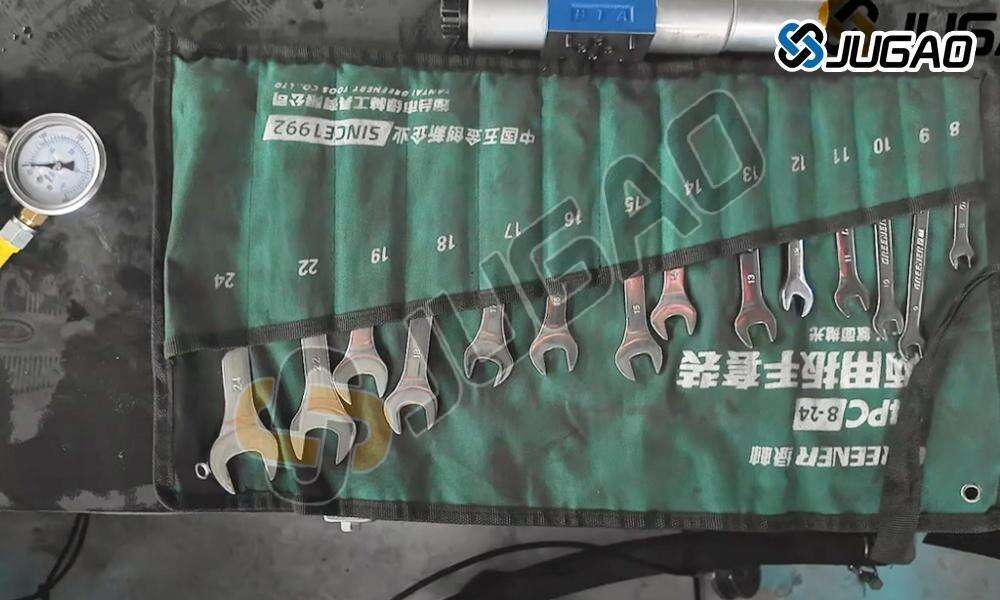
3. Required Tools & Materials
Metric hex wrench set (4mm-10mm)
Magnetic retrieval tools
Ultrasonic cleaning bath (optional)
Hydraulic seal kit (manufacturer specified)
Precision measuring instruments
Detailed Disassembly Procedure
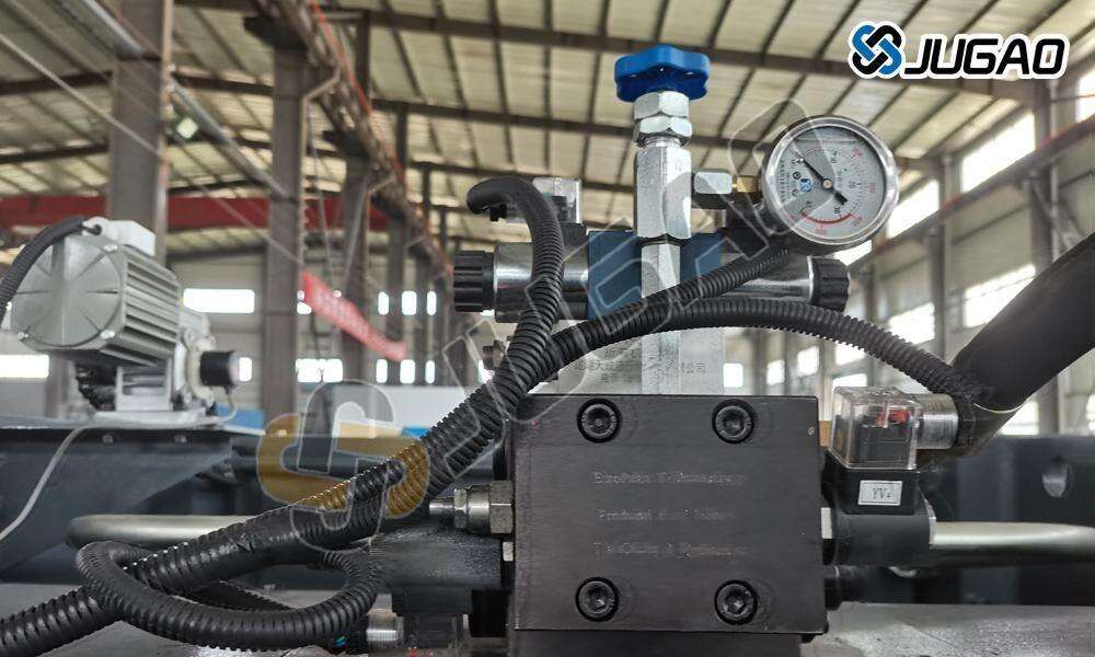
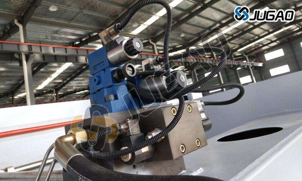
Step 1: Valve Group Isolation
1) Locate primary hydraulic valve manifold
2) Tag and photograph all hydraulic connections
3) Drain residual hydraulic fluid into approved containers
4) Disconnect electrical solenoids (note wiring configuration)
Step 2: Systematic Disassembly
| ComponentLayer | FastenerSize | TorqueSpec | SpecialNotes |
| OuterCover Plate | M5Hex | 8-10Nm | Containsprimary O-ring |
| IntermediatePlate | M8Hex | 12-15Nm | Housesrelief valve spring |
| ValveCore Housing | M6Hex | 10-12Nm | Magneticretrieval recommended |
Step 3: Component Inspection
1. Valve Core Examination
Check for scoring/wear patterns (use 10× magnification)
Measure core diameter (tolerance ±0.01mm)
Verify smooth travel through bore
2. Spring Evaluation
Free length measurement
Compression test (compare to OEM specs)
Visual inspection for fatigue cracks
3. Seal Assessment
Hardness check (Shore A scale)
Cross-section deformation analysis
Surface imperfection detection
Advanced Cleaning Techniques
Mechanical Cleaning Process
1. Primary Debris Removal
Use lint-free swabs with mineral spirits
Magnetic particle extraction
Compressed air blast (regulated to 2 bar)
2. Precision Surface Treatment
Ultrasonic cleaning (20kHz, 60°C solution)
Micro-abrasive polishing (600+ grit)
Final solvent rinse (approved hydraulic fluid)
Contamination Analysis
Collect particulate samples for:
Metallurgical composition
Particle size distribution
Source identification (wear vs. contamination)
Reassembly & Testing Protocol
Precision Reassembly Steps
1. Component Lubrication
Apply manufacturer-specified assembly lubricant
Coat all sliding surfaces evenly
Protect seals with hydraulic fluid film
2. Torque Sequence
Follow star pattern tightening
Use calibrated torque wrench
Three-stage torque process (50%, 80%, 100%)
3. Alignment Verification
Dial indicator check (runout<0.02mm)
Solenoid actuation test (bench test)
Manual spool movement verification
System Commissioning
1. Pre-Start Checks
Verify fluid level and condition
Inspect for leaks (pressure-less)
Confirm electrical connections
2. Operational Testing
Low-pressure cycle test (25% rated)
Full stroke verification
Pressure ramp test (incrementally to 100%)
3. Performance Validation
Response time measurement
Pressure holding test
Cycle consistency evaluation
Maintenance Interval Recommendations
| Component | InspectionFrequency | ReplacementCriteria |
| ValveSpool | 500hours | >0.03mmwear |
| Seals | 2,000hours | Hardnesschange >15% |
| Springs | 5,000hours | >5%length deformation |
| EntireAssembly | 10,000hours | Cumulativewear indicators |
Troubleshooting Matrix
| Symptom | ProbableCause | CorrectiveAction |
| Delayedresponse | Contaminatedspool | Ultrasoniccleaning |
| Pressurefluctuation | Wornseals | Fullseal replacement |
| Externalleakage | Impropertorque | Re-torqueto spec |
| Erraticmovement | Springfatigue | Springkit replacement |
Advanced Maintenance Tips
1. Predictive Maintenance
Implement oil analysis program
Install particle counters
Trend performance data
2. Component Upgrades
Consider coated spools for extended life
Upgrade to high-cycle seals
Install quick-disconnect fittings
3. Documentation Standards
Maintain component history logs
Photograph critical stages
Record torque values
Safety Compliance Checklist
ANSI B11.3 machine safety standards
OSHA lockout/tagout requirements
NFPA hydraulic system guidelines
Manufacturer-specific warnings
Conclusion
This professional maintenance protocol extends valve group service life by40-60% while ensuring optimal press brake performance. Regular maintenancefollowing these procedures prevents 85% of hydraulic-related downtime. Alwaysconsult OEM manuals for model-specific requirements and keep detailed servicerecords for warranty compliance.

