





Common Problems with Servo Motors in Use
Servo systems are a crucial component of electromechanical products, offering the highest levels of dynamic response and torque density. Therefore, the development trend of drive systems is to replace traditional hydraulic, DC, stepper, and AC variable frequency drives with AC servo drives, achieving a new level of system performance, including shorter cycle times, higher productivity, better reliability, and longer lifespan. To achieve better performance from servo motors, it is essential to understand their usage characteristics.
Common Problems with Servo Motors in Use
Problem 1: Noise and Instability
Customers often experience excessive noise and unstable operation when using servo motors on machinery. Many users' first reaction is to assume the servo motor is of poor quality, as sometimes replacing it with a stepper motor or variable frequency motor results in significantly less noise and instability. Superficially, this seems to be the servo motor's fault, but a careful analysis of its working principle reveals this conclusion to be completely incorrect.
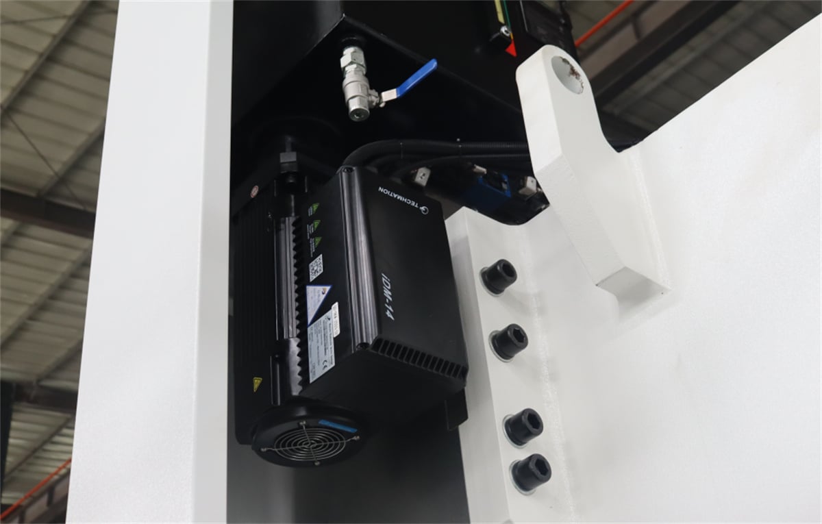
An AC servo system includes: a servo drive, a servo motor, and a feedback sensor (generally, servo motors have a built-in optical encoder). All these components operate within a closed-loop control system: the driver receives parameter information from the outside, then supplies a certain current to the motor, which converts this current into torque to drive the load. The load moves or accelerates/decelerates according to its own characteristics. Sensors measure the load's position, causing the drive to compare the setpoint information value with the actual position value. Then, by adjusting the motor current, the actual position value is kept consistent with the setpoint information value. When a sudden change in load causes a speed change, the encoder detects this speed change and immediately responds to the servo driver. The driver then adjusts the current supplied to the servo motor to accommodate the load change and returns to the set speed. An AC servo system is a highly responsive, fully closed-loop system. The time lag between load fluctuations and speed correction is very fast. Therefore, the real limiting factor for system response is the transmission time of the mechanical connection devices.
Problem Two: Inertia Matching
Inertia issues are frequently encountered during servo system selection and debugging!
Specifically, this manifests in the following ways:
1. When selecting a servo system, in addition to considering factors such as motor torque and rated speed, we also need to calculate the inertia of the mechanical system converted to the motor shaft. Then, based on the actual mechanical action requirements and the quality requirements of the machined parts, we select a motor with a suitable inertia value.
2. During debugging (in manual mode), correctly setting the inertia ratio parameter is a prerequisite for fully utilizing the optimal performance of the mechanical and servo systems. This is particularly prominent in systems requiring high speed and high precision (Delta servo inertia ratio parameters are 1-37, JL/JM).
Impact: Transmission inertia affects the accuracy, stability, and dynamic response of the servo system. A large inertia results in a large mechanical constant, slow response, and a decrease in the system's natural frequency, making it prone to resonance. This limits the servo bandwidth and affects servo accuracy and response speed. Appropriately increasing the inertia is only beneficial for improving low-speed crawling. Therefore, in mechanical design, the inertia should be minimized as much as possible without affecting the system's rigidity.
How to determine the dynamic characteristics of a mechanical system: When measuring the dynamic characteristics of a mechanical system, the smaller the inertia, the better the system's dynamic response; the larger the inertia, the greater the load on the motor, and the more difficult it is to control. However, the inertia of the mechanical system must match the inertia of the motor. Different mechanisms have different choices of inertia matching principles, and these choices have different effects.
For example, when a CNC machining center performs high-speed cutting using a servo motor, an increase in load inertia will cause the following:
1. When control commands change, the motor will take longer to reach the speed required by the new command;
2. When the machine tool performs rapid arc-shaped cutting along two axes, significant errors will occur. Generally, under normal conditions, if JL≦JM, the above problems will not occur;
3. When JL≧3×JM, the motor's controllability will significantly decrease, especially noticeable during high-speed curve cutting.
Different mechanical actions and processing quality requirements dictate different relationships between JL and JM. The determination of inertia matching needs to be based on the mechanical process characteristics and processing quality requirements.
Question 3: Servo Motor Selection
After selecting the mechanical transmission scheme, the model and size of the servo motor must be selected and confirmed.
(1) Selection Conditions
Generally, the following conditions must be met when selecting a servo motor:
1. Maximum motor speed > maximum required system speed.
2. Motor rotor inertia matches load inertia.
3. Continuous load working torque ≤ motor rated torque.
4. Maximum motor output torque > maximum required system torque (torque during acceleration).
(2) Selection Calculation
1. Inertia matching calculation (JL/JM)
2. Rotational speed calculation (load end speed, motor end speed)
3. Load torque calculation (continuous load working torque, torque during acceleration)

