





Detailed Introduction to Plate Bending Machine Performance
I. Working Principle of the Plate Bending Machine
Widely used in industries such as petrochemicals, shipbuilding, pressure vessel manufacturing, and general machinery manufacturing.
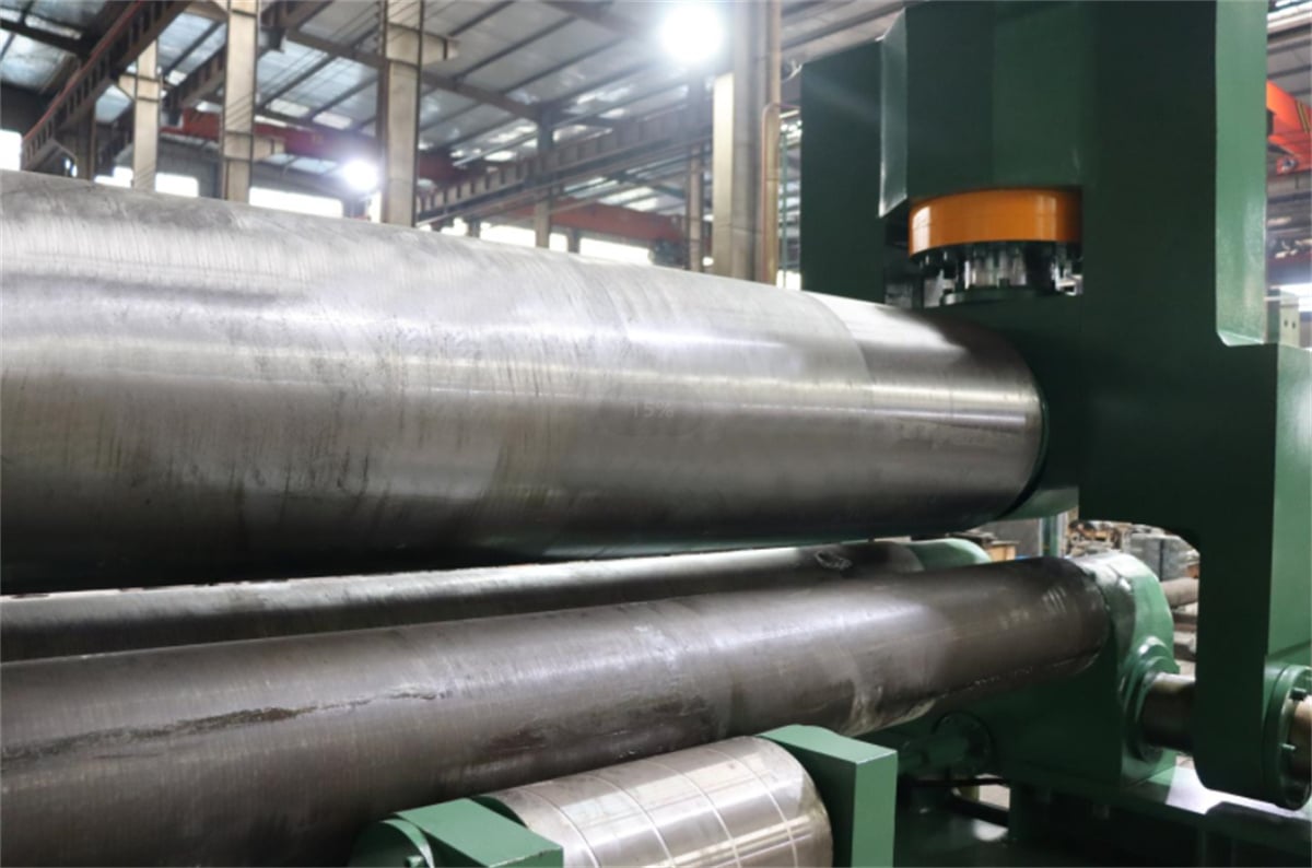
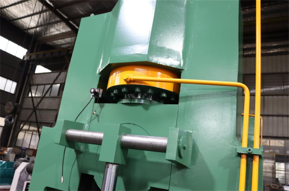
The machine's top roll is positioned symmetrically between the two bottom rolls; hydraulic oil acting on a piston within a hydraulic cylinder drives the top roll to move vertically (up and down). Meanwhile, the final-stage gear of the main reducer drives the gears of the two bottom rolls to rotate, providing the torque required for bending the plate. Through the downward pressure of the top roll and the rotation of the bottom rolls, the metal plate undergoes continuous bending over multiple passes, resulting in permanent plastic deformation and forming the desired cylindrical or conical shapes (or segments thereof). A disadvantage of this hydraulic three-roll plate bending machine is that the ends of the plate require pre-bending using separate equipment.
II. Troubleshooting the Plate Bending Machine
1. Interface Signal Check: By checking the machine tool control system's interface signals via the programmable controller and comparing them against the correct signals listed in the interface manual, the specific point of failure can be identified.
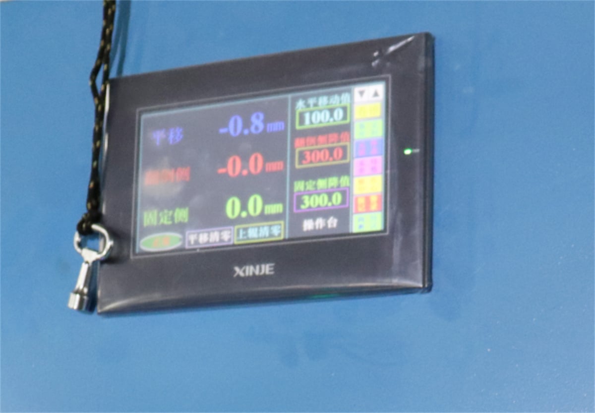
2. Instrument Measurement: When a system fault occurs, standard electrical testing instruments and tools are used to measure parameters such as voltage, power supply, and pulse signals—referencing the system and machine circuit diagrams—to pinpoint the fault. For instance, if the input voltage exceeds limits, a voltmeter can measure the mains voltage, or a voltage tester can provide real-time monitoring to rule out other causes. An oscilloscope can be used if a fault occurs in the position control loop.
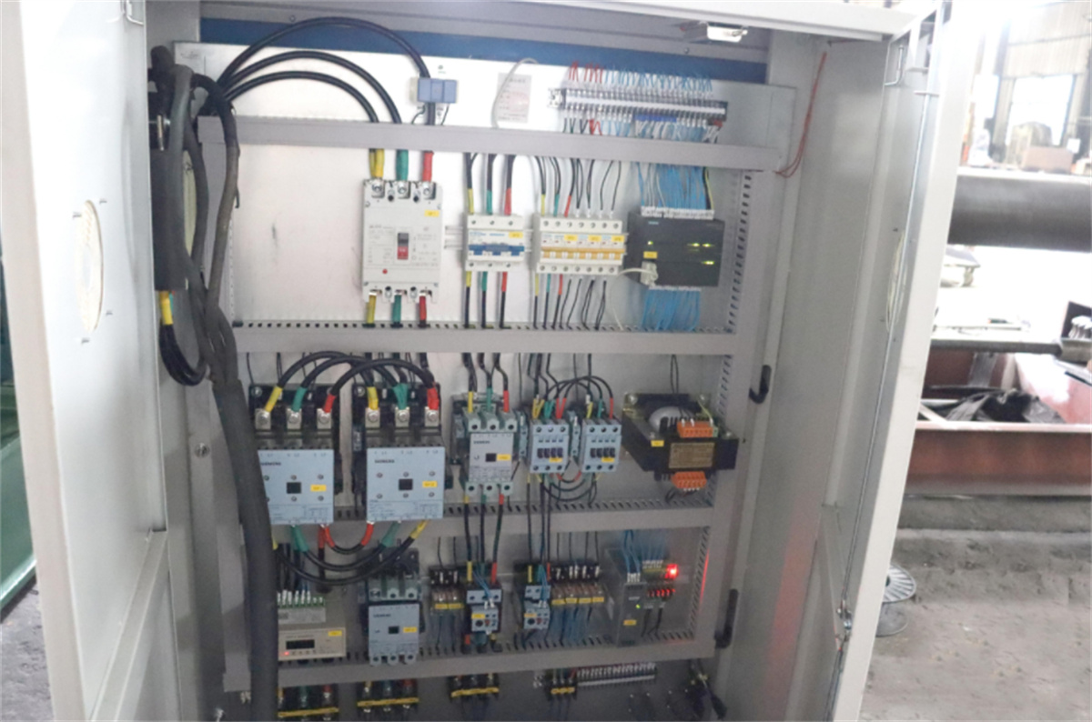
3. PLC Interrupt Status Analysis: When a fault occurs in the programmable controller, the cause of the interrupt is stored in an interrupt stack. Using the machine's programmer while the system is stopped, the operator can retrieve the interrupt stack and block stack to identify the fault based on the indicated cause.
III. Effective Measures to Improve the Sealing Performance of Plate Bending Machines
Regardless of the size of the enterprise using a plate bending machine, or the manufacturing facility producing it, the equipment must be fitted with sealing devices to prevent leakage and the ingress of dust during processing operations.
Seals are the components within the plate bending machine's hydraulic system responsible for sealing; they serve to prevent the leakage of fluids or solid particles from between mating surfaces and to block external impurities—such as dust and moisture—from entering the machinery. External leakage of these seals results in the waste of working fluid, contamination of the machine and the environment, and can even lead to mechanical malfunctions or accidents involving equipment and personnel.
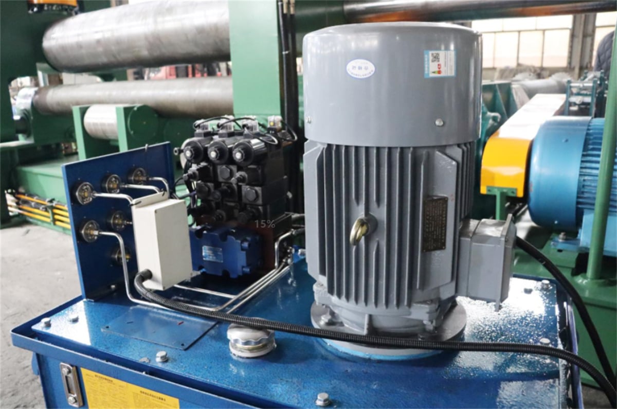
The operational reliability and service life of the seals within the hydraulic system are key indicators of the system's overall quality.
With the exception of clearance seals, sealing relies on components that restrict the gap between mating surfaces to a size smaller than that required for the fluid to pass through. In contact-type sealing applications, seals are generally categorized into two types: compression-type self-sealing seals and self-tightening self-sealing seals (also known as lip seals). However, the factors influencing the performance of these various seals differ; for instance, the sealing performance of a three-roll plate bending machine is affected by variables such as temperature, pressure, and the specific medium involved.
IV. Transmission Performance of Plate Bending Machines
When a speed reducer is utilized in the transmission system of a plate bending machine, it achieves speed reduction by transferring power from the high-speed electric motor through an input shaft—featuring a gear with fewer teeth—to mesh with a larger gear on the output shaft. The speed reducer used in a plate rolling machine is a power transmission mechanism that employs a gear-based speed converter to reduce the motor's rotational speed to the desired level while generating higher torque.
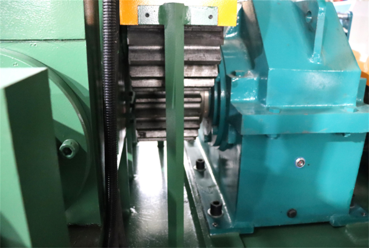
While reducing speed, the reducer increases output torque—calculated by multiplying the motor's output by the reduction ratio—though care must be taken not to exceed the reducer's rated torque. Additionally, the speed reduction lowers the load's moment of inertia; the reduction in inertia is proportional to the square of the reduction ratio.

