





A Complete Guide to Selecting the Ideal Punch & Die Set for Metal Fabrication
Achieving precise hole geometries, clean edge profiles, and consistent production output hinges directly on configuring your tooling correctly. When work schedules are tight, deploying standardized, generic punch-and-die units frequently leads to rapid tool wear, excessive burring, and operational strain on your machinery. In this comprehensive guide, JUGAO outlines the essential criteria and step-by-step procedures to assist engineering and production teams in picking the perfect punch and die configuration, optimizing cycle efficiency, minimizing material scrap, and extending machine service life.
Essential Parameters for Punch & Die Selection
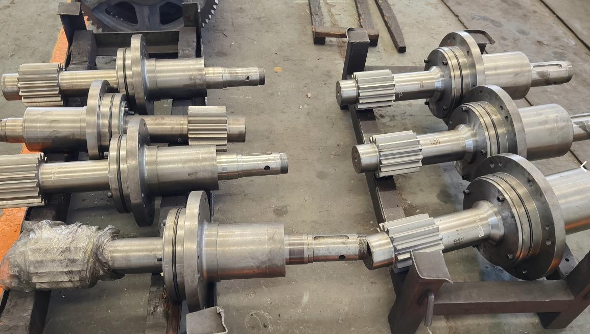
Workpiece Material Characteristics and Sheet Thickness
The physical properties of the sheet metal dictate tool steel requirements and overall component longevity. Standard carbon steels up to 3 mm in thickness typically perform reliably with conventional tool steels. Conversely, working with abrasive aluminum, stainless steel, or high-tensile alloys demands premium high-speed steel (HSS) or carbide-tipped punches. JUGAO recommends strictly evaluating metal thickness against the punch diameter and matrix opening to prevent premature galling and tool chipping.
Target Aperture Geometry and Dimensions
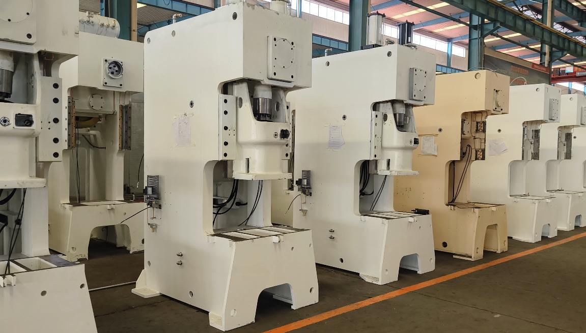
Whether your production requires standard round holes, elongated slots, or intricate custom profiles, tool geometry must mirror the desired finished specification. Intricate radii or micro-scale perforations mandate smaller punch tip radii and narrower die gaps—typically calculated between 5% and 7% of sheet thickness—whereas larger circular punches accommodate gaps up to 10% without inducing excessive burrs.
Press Tonnage Capacity and Tooling Load Tolerances
To preserve equipment integrity, total punching resistance should remain safely within 80% of the machine's maximum rated capacity. Calculate the required shearing force (shear perimeter × sheet thickness × material shear strength) and cross-reference it against machine tonnage and punch compression thresholds. For high-load operations, JUGAO advises incorporating stripper plates and using high-grade coated punches to balance lateral forces.
Formulas for Determining Die Gap Clearances
Insufficient clearance increases punch force, accelerates wear, and generates heavy rollover. Excessive clearance leaves rough, torn edges and pronounced rollover burrs. A practical baseline calculation applies a material multiplier: Die Clearance = Sheet Thickness × Multiplier (0.06 for soft aluminum alloys, 0.08 for structural carbon steel, and 0.10 for stainless steel grades). JUGAO highly recommends fine-tuning these parameters during initial test hits.
Surface Coatings and Defensive Treatments
Specialized surface coatings such as TiN, TiCN, and AlCrN significantly reduce friction and prevent galling when processing sticky or tough metals. For standard carbon steel up to 4 mm, TiN provides an ideal cost-to-performance balance; TiCN is suited for tougher alloy grades; and AlCrN delivers maximum wear resistance during extended production runs involving 304 stainless steel or advanced high-strength steels (AHSS).
Step-by-Step Procedure for Perfect Tool Matching
Step 1: Validate Blueprint Specifications with Engineering
Review technical drawings to verify hole centerlines, dimensional tolerances, and edge finish criteria prior to tool setup. This initial verification eliminates costly scrap and rework downstream.
Step 2: Select Punch Tooling Grade and Hardness Level
While standard tool steel suffices for short prototyping batches, continuous manufacturing demands heavy-duty HSS heat-treated to 60–62 HRC or powder metallurgy steels for maximum punch tip longevity.
Step 3: Establish the Correct Die Matrix Opening
Calculate the die clearance using the recommended material factors, round to the nearest 0.1 mm increment, and incorporate a slight micro-bevel along the matrix land to eliminate slug pulling.
Step 4: Inspect Machine Alignment and Ram Perpendicularity
Even the finest tooling will suffer premature failure under a misaligned ram. Verify ram squareness, adjust machine gibs, and ensure the punch centers accurately within the stripper bore and die cavity through every stroke cycle.
Step 5: Execute Trial Punching and Perform Edge Inspection
Conduct test strikes on sample stock and evaluate the cut edge under 10× magnification. A clean, burnished shear band across 25% to 35% of the material thickness indicates optimal clearance; excessive rollover or sharp burrs signify the need for immediate adjustment.
Frequent Operational Errors and Prevention Strategies
• Applying Uniform Tool Sets Across Variable Sheet Materials: Tooling optimized for mild steel often chips or snaps when forced through hardened stainless grades. JUGAO recommends dedicating specific tool assemblies to distinct material families.
• Neglecting Stripper Plate Maintenance and Clearance: A loose or worn stripper plate allows sheet lifting during the retract stroke, leading to double-striking and punch head breakage. Replace stripper inserts whenever internal wear exceeds 0.3 mm.
• Operating Without Adequate Tool Lubrication: Unlubricated punching severely increases frictional heat buildup and accelerates material galling. JUGAO advises applying a thin layer of synthetic stamping lubricant per shift, especially during heavy stainless steel production.
Frequently Asked Questions (FAQ)
Q: How do I determine the precise clearance required for my punching application?
A: Clearance depends primarily on sheet thickness and material tensile strength. A baseline ratio of 5% of material thickness works well for mild steel, scaling up to 8%–10% for high-strength or stainless steels. Always validate edge quality with a sample test cut.
Q: Is it acceptable to combine punches and dies from different equipment manufacturers?
A: While mixing components is physically possible provided key mounting dimensions and keyways match, JUGAO strongly advises utilizing fully matched punch-and-die sets to ensure concentric alignment, balanced load distribution, and maximum tool longevity.
Q: At what intervals should punch tips be re-ground or replaced?
A: Perform visual and dimensional inspections of punch edges every 10,000 punching cycles. If edge rounding exceeds standard radius limits or cut quality deteriorates, re-grind the punch face promptly or replace the component to protect the matrix die from damage.
Summary & Technical Support
Selecting the ideal punch and die setup requires harmonizing material specifications, tooling geometry, and press force dynamics. By rigorously verifying metal hardness, selecting targeted surface coatings, and adhering to disciplined setup practices, manufacturers can significantly extend tool life, maintain superior hole tolerances, and eliminate unnecessary downtime. For customized tooling recommendations or specialized application support, contact the JUGAO technical engineering team today.

