


E21 NC Pres Fren Sistemi’ni Maksimum Verimle Nasıl İşletirsiniz?
İçindekiler Tablosu
1. E21 Sistemi Kullanım Kılavuzuna Genel Bakış
2. Adım 1: Hidrolik Yağ Doldurma ve Elektriksel Bağlantı Kurma
○ Hidrolik Yağ Deposunun Doğru Şekilde Doldurulması
○ NC Bükme Presi İçin Güç Bağlantısı
○ Ana Güç Kaynağının Etkinleştirilmesi
○ Makinenin Güç Anahtarının Açılması
○ Ayak Pedalı Anahtarının Bağlanması
○ E21 Bükme Presinin Çalıştırılması
○ Pompa Anahtarının Doğru Aktivasyonu
○ Acil Durdurma Fonksiyonunun Ayak Pedalından Devreden Çıkarılması
○ Makinenin Başlatılması İçin ENTER Tuşuna Basılması
○ Ana Motorun Dönme Yönünün Doğrulanması
○ Saat Yönünde Dönme = Normal İşletim
○ Acil Durdurma İşlemi
○ İki Kabloyu Değiştirerek Kablolamanın Düzeltilmesi
3. Adım 2: Makine Açılış Prosedürü
○ E21 NC Şerit Bükme Presinin Açılması
○ Hidrolik Yağ Pompasının Doğru Şekilde Çalıştırılması
○ Acil Durdurma Anahtarını Serbest Bırakma
○ Ayak Pedalındaki Acil Durdurma (E-Stop) Fonksiyonunu Serbest Bırakma
○ ENTER Tuşuyla Pres Bükme İşlemini Başlatma
4. Adım 3: Çalışma Modlarının Açıklaması
○ E21 Sisteminde Tekli Mod
○ E21 Sisteminde Jog Modu
○ E21 Sisteminde Sürekli Mod
5. Adım 4: Sistem Çalıştırması ve Kontrolü
○ E21 NC Pres Bükme Makinesi için Programlama Talimatları
○ Bükme İşlemleri İçin YP=93 ve XP=50 Ayarlanması
○ Hedef açıya 93 Derecelik Eğim Kalibre Etmek
○ Eğme Uzunluğunun Doğruluğunu Ayarlamak
6. Adım 5: Sistem Kalibrasyonu Süreci
○ E21 Pres Bükme Makinesi için Y-Ekseni Kalibrasyonu
○ Hassas Bükme İçin YP’yi İnce Ayarlama
○ X-Ekseni Kalibrasyon Talimatları
○ Kurulum Moduna Girmek İçin "P" Tuşuna Çift Tıklayın
○ CONST Arayüzünde Şifre Olarak 1212 Girin
○ ÖĞRET Sayfasında Uygun X-Tea’yı Seçmek
○ Tam Gerekli Eğme Uzunluğunu Girmek
○ Bükme İşlemlerini Devam Ettirmek İçin "P" Tuşuna Çift Tıklayın
7. Adım 6: Pratik Üretim Demonstrasyonu
○ 90 Derecelik Bükme Açısı Elde Etmek
○ E21 Sisteminde Bükme Uzunluğunu Anlamak
8. Adım 7: Doğru Kapatma Prosedürü
○ Pompa Durdurma Anahtarını Kullanmak
○ Güvenlik Amaçlı Acil Durdurma (E-Stop) Butonunu Devreye Sokmak
○ E21 NC Bükme Presini Doğru Şekilde Kapatmak
9. Sonuçlar
E21 NC bükme pres sisteminin kullanımını ustalaşmak, birçok operatör için zorlu bir görev olabilir. Bu kapsamlı işletme kılavuzu, bu ekipmanı kolayca kullanmanızı ve optimize etmenizi sağlamak amacıyla her adımı size adım adım açıklar. Kılavuz, E21 NC bükme presinin kurulumu, günlük işletimi ve temel bakımı ile ilgili tüm temel prosedürleri kapsar; böylece makinenin işletme verimliliğini en üst düzeye çıkarmak için gerekli bilgiye sahip olursunuz. Şimdi, bu sistemin ayrıntılı adım adım kurulum ve işletme yönergelerine geçelim.
E21 Sistemi İşletme Kılavuzuna Genel Bakış
Modern metal işlemenin temel süreçlerinden biri olan sac metal bükme işlemlerinde pres freni, vazgeçilmez bir ekipman parçasıdır. Bu kılavuz, E21 kontrol sistemiyle donatılmış NC pres frenleri için ayrıntılı, adım adım işlem talimatları sunar. Pres frenleriyle yeni tanışan bir operatör müsünüz yoksa bu alanda deneyimli bir uzman mı? Her iki durumda da bu kılavuz, E21 NC pres freninin kurulumunu, çalıştırılmasını ve kalibrasyonunu başarıyla gerçekleştirmenize yardımcı olacak; böylece ekipman üretim sürecinde en iyi performansı gösterecektir.
Adım 1: Hidrolik Yağ Doldurma ve Elektrik Bağlantısı
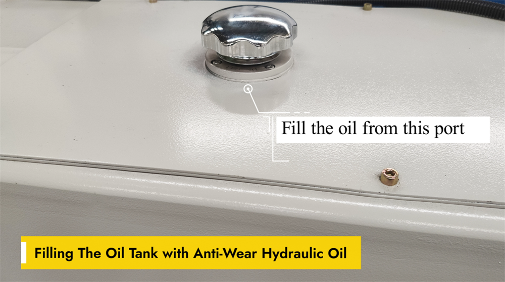
Hidrolik Yağ Deposunun Doğru Şekilde Doldurulması
E21 NC bükme makinesinin sorunsuz çalışması, hidrolik yağ deposunun aşınmaya dayanıklı hidrolik yağ ile doğru şekilde doldurulmasına bağlıdır. Bu özel yağ, hidrolik bileşenler arasındaki sürtünmeyi azaltır ve erken aşınmayı önleyerek makinenin genel performansını artırır. Yeniden doldurma işlemi sırasında makinedeki özel yağ doldurma ağzını kullanın ve yağ seviyesinin üreticinin önerdiği aralıkta kalmasını sağlayın. Depoyu aşırı doldurmak veya düşük kaliteli hidrolik yağ kullanmak, sistemin verimsiz çalışmasına ve hatta bileşenlerde kalıcı hasarlara neden olabilir. Pres bükme makinesinin optimal çalışma koşullarını korumak için yağ seviyesini düzenli olarak kontrol edin ve gerekli olduğunda hidrolik yağı değiştirin.
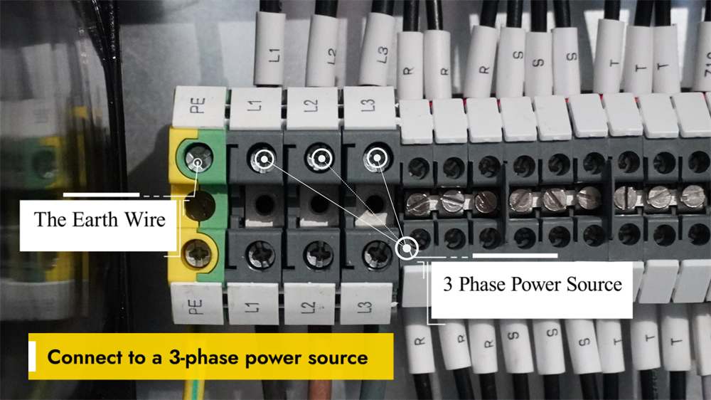
NC Bükme Makinesi İçin Güç Bağlantısı
NC pres bükme makinesini çalıştırmadan önce, makinenin kararlı bir üç fazlı güç kaynağına bağlanması kritik öneme sahiptir; bu, kararlı performansı sağlamak ve elektriksel arızaları önlemek için gereklidir. Güç kaynağının geriliminin makinenin belirtilen elektriksel parametreleriyle eşleştiğini doğrulayın. Tüm kablolama işleri, güvenli bağlantıları sağlamak ve elektrik güvenlik yönetmeliklerine tam uyum sağlamak üzere yetkili bir elektrikçi tarafından tamamlanmalıdır. Kablolama işlemi tamamlandıktan sonra, elektriksel güvenlik risklerini ortadan kaldırmak için makinenin topraklamasını kontrol edin. Ana güç anahtarını açın ve kontrol panelinde herhangi bir hata kodu veya uyarı mesajı olup olmadığını inceleyin. Panelde herhangi bir anormallık görüntülenmiyorsa sistem çalıştırılmaya hazırdır. Ekipmanın güvenli ve verimli kullanımında üreticinin talimatlarına her zaman uyun.
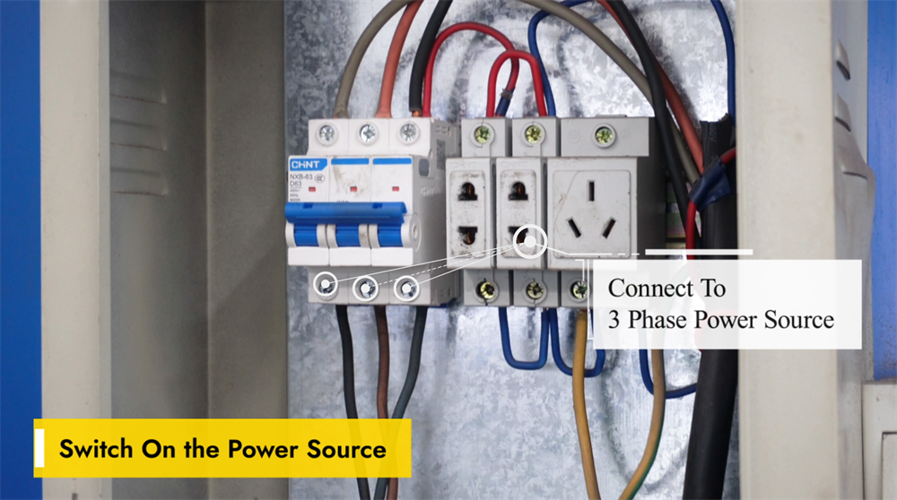
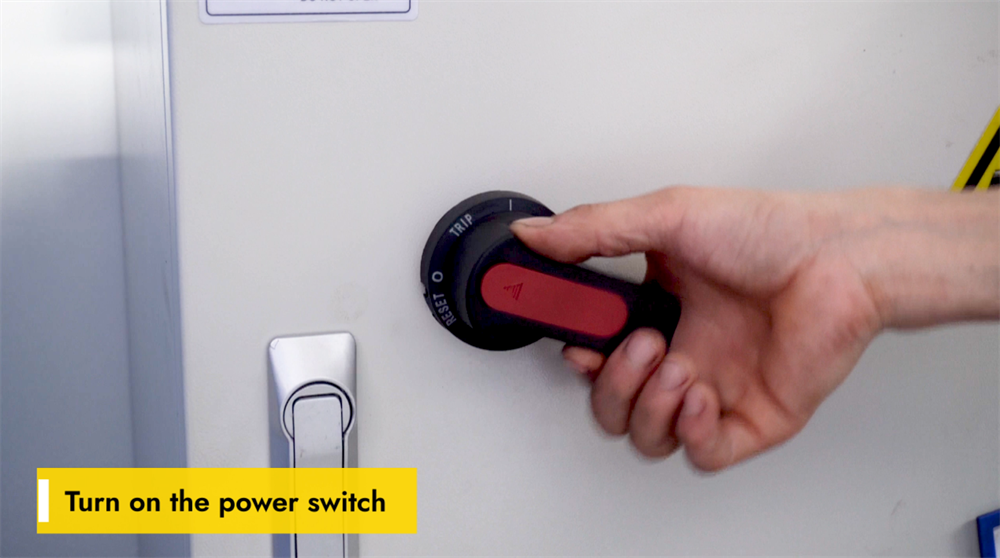
Ana Güç Kaynağını Etkinleştirme
E21 NC pres bükme makinesini çalıştırmadan önce, makinenin kararlı bir güç kaynağına bağlı olduğunu ve voltajın ekipmanın gereksinimlerini karşıladığını doğrulayın; böylece elektrik arızaları önlenir. Ana güç anahtarını, genellikle makinenin yan veya arka kısmında yer alan konumdan bulun ve anahtarı "AÇIK" konumuna getirin. Sistemin başlatma işlemini tamamlaması için birkaç saniye bekleyin; kontrol paneli başlangıç bilgilerini göstermeli ve sistemin kullanıma hazır olduğunu belirtmelidir. Panelde herhangi bir hata kodu görüntülenirse, sorun giderme çözümleri için resmi işletme kılavuzuna başvurun. Herhangi bir sac metal bükme işlemine başlamadan önce tüm güvenlik protokollerine kesinlikle uyun.
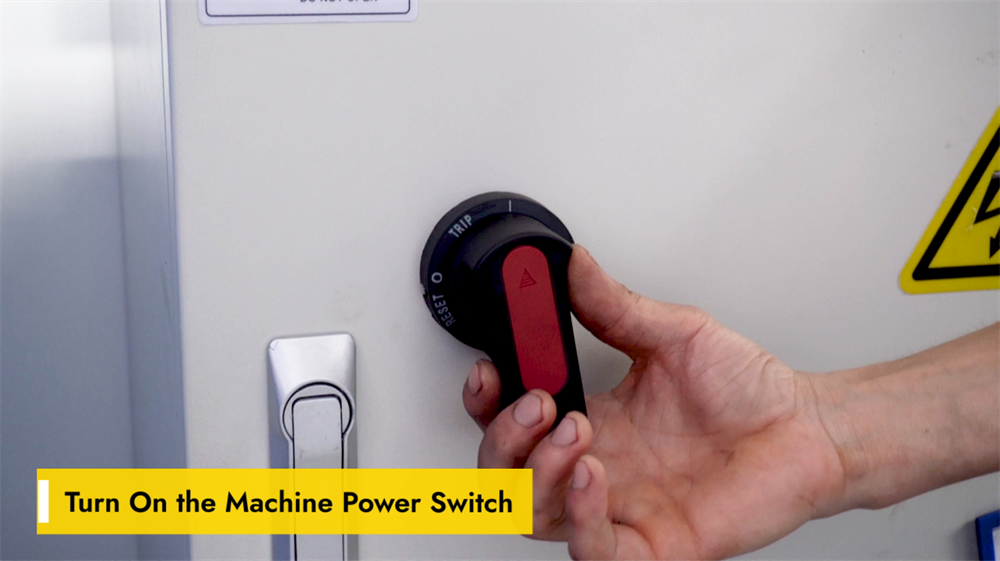
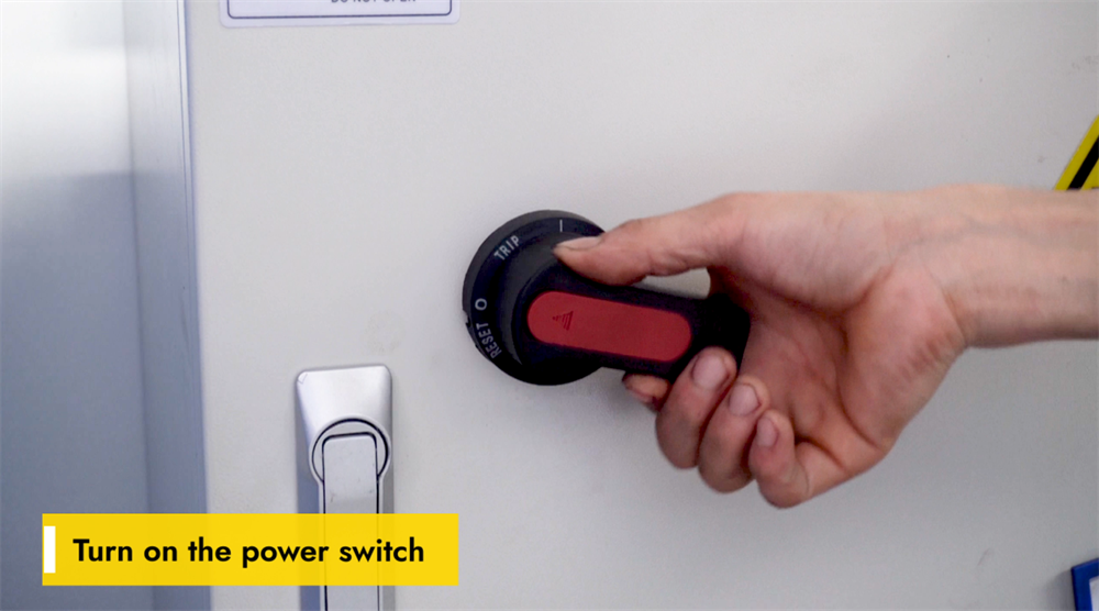
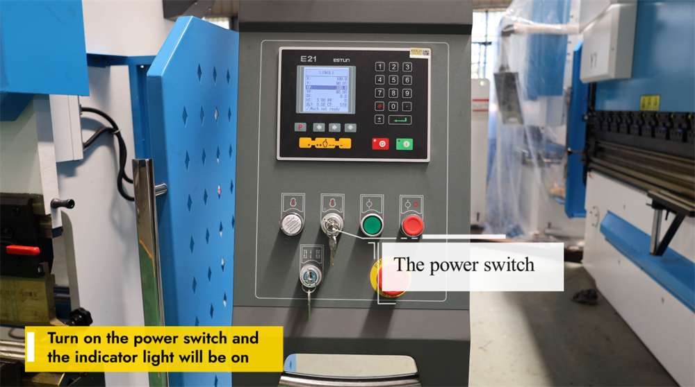
Makinenin Güç Anahtarını Açma
E21 NC pres bükme makinesini çalıştırmadan önce güç kaynağının kararlı olduğundan ve belirtilen gerilim gereksinimlerini karşıladığında emin olun. Ana güç anahtarını makinenin kontrol paneli veya elektrik dolabında bulun ve "AÇIK" konumuna getirin; ardından sistemin başlatılmasını bekleyin. Kontrolör ekranının aydınlandığını ve başlangıç arayüzünü yüklediğini kontrol edin; ayrıca makineden gelen herhangi bir anormal sesi dinleyin, çünkü bu durum temeldeki elektriksel sorunları gösterebilir. Sistem normal şekilde başlatılamazsa, güç kaynağını ve acil durdurma düğmesini arızalı olup olmadığını kontrol edin. Makineyi çalıştırmadan önce her zaman güvenlik protokollerine uyun ve uygun kişisel koruyucu ekipmanları takın.
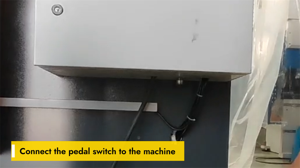
Ayak Pedalı Anahtarının Bağlanması
E21 NC pres bükme makinesinin doğru çalışması için ayak pedalı anahtarının güvenli bir şekilde bağlanması esastır. Öncelikle makinenin kontrol paneli veya temel ünitesinde özel ayak pedalı bağlantı portunu bulun. Ayak pedalı konektörünü bu porta hizalayın ve bağlantının sıkı olmasını sağlamak için tıklayana kadar sağlam bir şekilde takın; böylece işlem sırasında kazara bağlantının kopması önlenir. Bağlantı tamamlandıktan sonra, pedala hafifçe basarak tepkisini test edin. Makine pedal girişine yanıt vermiyorsa, gevşek kablo bağlantılarını veya güç kaynağı sorunlarını kontrol edin. Doğru şekilde bağlı bir ayak pedalı, yalnızca operasyonel kontrolü değil, aynı zamanda bükme işlemlerinde işyeri güvenliğini de artırır.
E21 Pres Bükme Makinesinin Açılması
E21 NC bükme makinesini çalıştırmaya başlamak için öncelikle makinenin kontrol panelindeki ana güç anahtarını bulun ve ekipmanın kararlı bir güç kaynağına bağlı olduğunu doğrulayın. Gücü "AÇIK" konumuna getirin; gösterge ışıkları veya kontrol ekranı aktive olacak ve makinenin başarıyla çalıştırıldığını onaylayacaktır. Herhangi bir ileri işlem yapmadan önce sistemin başlatılmasını tamamlaması için birkaç saniye bekleyin. Makine açılmazsa, güç kaynağını, acil durdurma düğmesini ve devre kesicileri kontrol ederek işlevsel sorunları tespit edin ve çözün. Makinenin elektriksel bileşenleriyle çalışırken her zaman güvenlik kurallarına uyun.
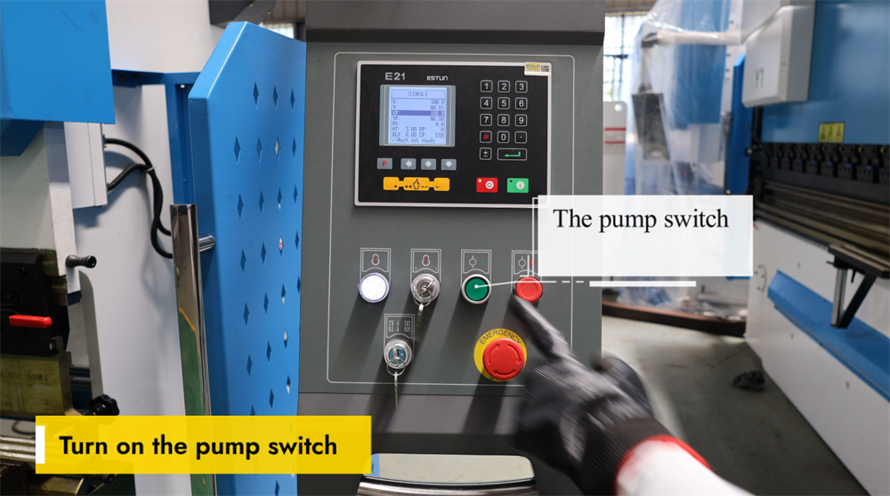
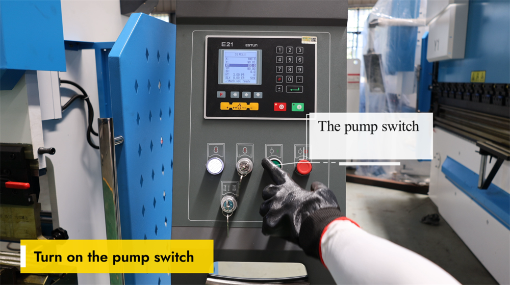
Pompa Anahtarının Doğru Aktivasyonu
E21 NC pres bükme makinesini çalıştırmadan önce makinenin güç kaynağına doğru şekilde bağlı olduğunu doğrulayın. Kontrol panelindeki pompa anahtarını bulun ve hidrolik sistemi etkinleştirmek için açın. Hidrolik pompasının sorunsuz çalıştığını gösteren sabit bir uğultu duyulmalıdır. Bu aşamada hidrolik yağ seviyesini kontrol edin ve sistemi yağ sızıntıları veya anormal sesler açısından inceleyin. Hidrolik sistem çalışmazsa, güç bağlantılarını ve acil durdurma düğmesini arızalı olup olmadığını kontrol edin. Doğru şekilde etkinleştirilmiş bir hidrolik pompa, stabil hidrolik basıncı ve sorunsuz bükme işlemlerini sağlar; böylece sac metal bükme sürecinde hatalar önlenir. Makineyi her zaman güvenlik kurallarına uyarak çalıştırın.

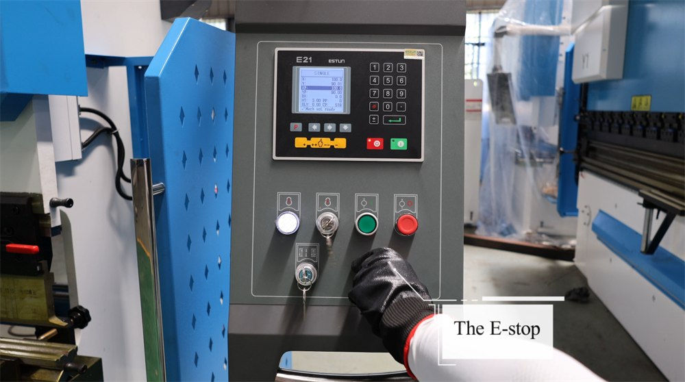
Ayak Pedalındaki Acil Durdurma Fonksiyonunun Devreden Çıkarılması
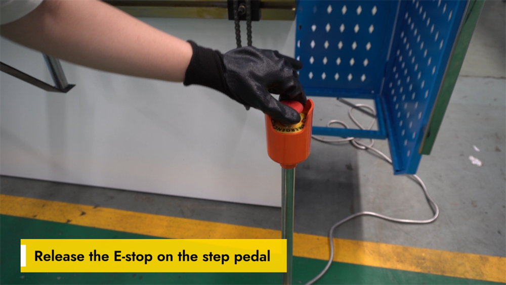
E21 NC pres bükme makinesinin normal çalışmasını geri yüklemek için önce ayak pedalındaki acil durdurma (E-stop) düğmesi serbest bırakılmalıdır. E-stop, işyeri kazalarını önlemek amacıyla tüm makine fonksiyonlarını anında durduran kritik bir güvenlik özelliğidir. E-stop'u serbest bırakmak için düğmeye sıkıca basın ve saat yönünün tersine çevirin (işlem, makine modeline göre hafifçe değişebilir); düğme orijinal konumuna geri döndüğünde serbest bırakılmış olur. E-stop serbest bırakıldıktan sonra sistemin başarıyla sıfırlandığını doğrulamak için kontrol panelini kontrol edin. Makineyi tekrar çalıştırmadan önce ayak pedalının her zaman sabit bir yüzey üzerinde yer aldığını mutlaka sağlayın. E-stop özelliğinin doğru şekilde kullanılması, işyeri güvenliğini sağlamak ve sorunsuz bükme işlemlerini sürdürmek açısından büyük önem taşır.
Makineyi başlatmak için ENTER Tuşuna Basın
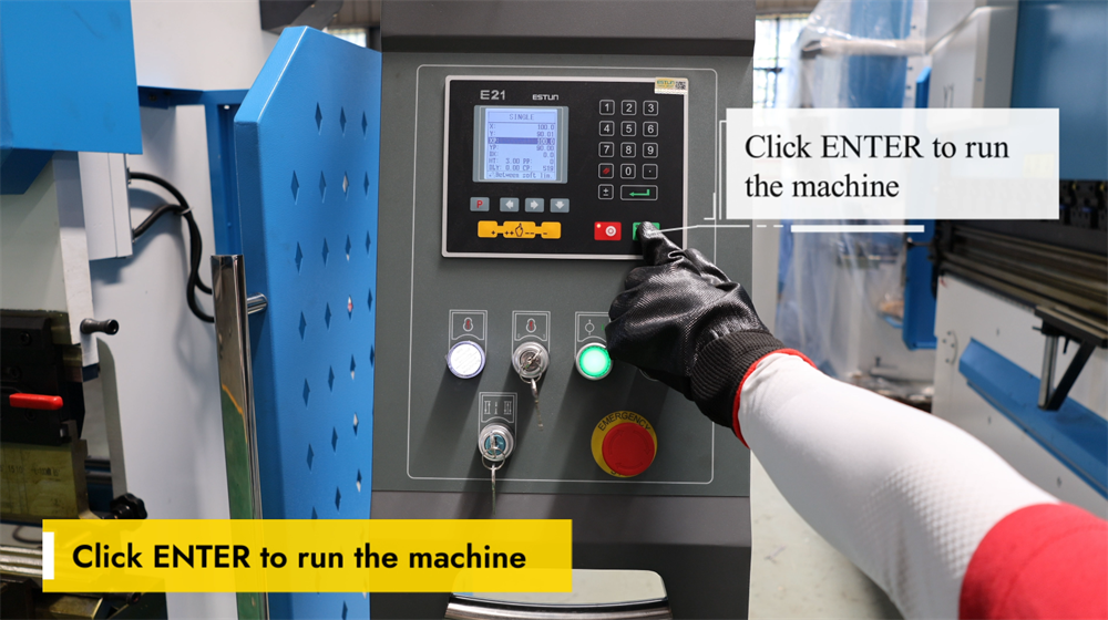
ENTER tuşuna basmak, E21 NC pres bükme makinesini başlatmak ve sac metal bükme işlemini başlatabilmek için son adımdır. Bükme açısı, malzeme kalınlığı ve arka ölçüm konumu dahil olmak üzere tüm bükme parametrelerini doğru bir şekilde ayarladıktan sonra, programlanmış işlemi onaylamak ve çalıştırmak için yalnızca ENTER tuşuna basın. Sistem daha sonra, önceden belirlenmiş parametrelere göre hassas bükme işlemi gerçekleştirmek üzere çapraz kolu (ram) kontrol eder. ENTER tuşuna basmadan önce her zaman iş parçasının doğru konumda olduğunu ve tüm güvenlik önlemlerinin alınmış olduğunu doğrulayın. Bu basit ancak kritik adım, sac metal imalatında hem verimliliği hem de ürün kalitesini optimize ederek etkili ve doğru metal bükme işlemlerini sağlar.
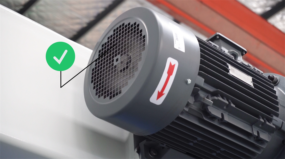
Ana Motorun Dönme Yönünün Doğrulanması
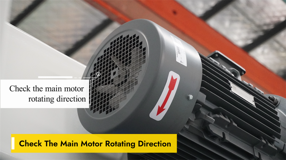
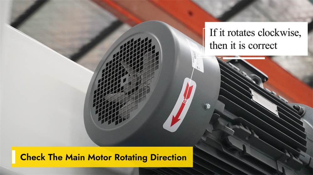
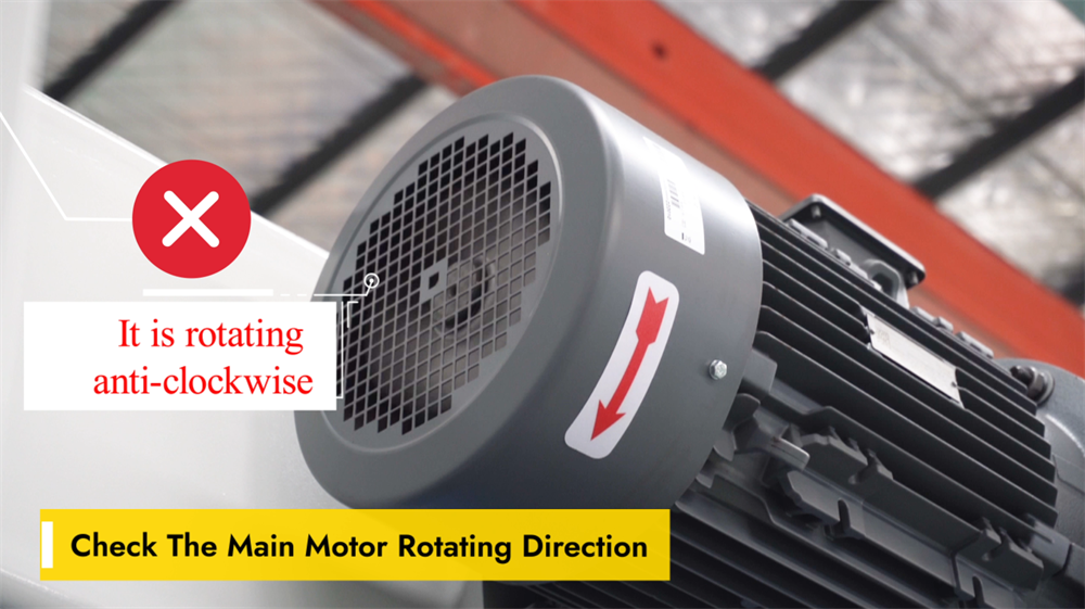
Ana motorun dönme yönünü doğrulamak, E21 NC bükme makinesi için kritik bir ön işlem adımıdır; çünkü yanlış dönme yönü, işletimsel verimsizliklere ve hatta sisteme zarar vermeye neden olabilir. Dönme yönünü kontrol etmek için makineyi çalıştırın ve motorun hareketini gözlemleyin. Eğer motor yanlış yönde dönüyorsa, faz sırasını ayarlamak ve dönme yönünü düzeltmek amacıyla herhangi iki güç hattının bağlantısını değiştirin. Bükme işlemlerine başlamadan önce mutlaka motorun düzgün ve doğru yönde çalıştığını teyit edin. Motorun dönme yönünün düzenli olarak kontrol edilmesi, bileşenlerde gereksiz aşınmayı önler ve tutarlı bükme hassasiyeti ile uzun makine ömrünü sağlar.
Saat Yönünde Dönme = Normal İşletim
E21 NC pres bükme sistemi çalıştırılırken ayar düğmesinin ve ana motorun doğru yönde döndüğünden emin olmak esastır. Saat yönünde bir dönüş, genellikle makinenin hareketli parçalarının düzgün çalıştığını gösterir; bu da hassas konumlandırma ve tutarlı bükme doğruluğu açısından kritik öneme sahiptir. Saat yönünün tersine bir dönüş, sistem ayarlarının yanlış olduğunu işaret edebilir ve bu durum bükme açılarında hatalara veya bileşenlerin hizalanmamasına neden olabilir. Üretim sorunlarını önlemek için herhangi bir bükme işlemine başlamadan önce mutlaka dönüş yönünü doğrulayın. Doğru makine kurulumu ve kalibrasyonu, yalnızca işletme verimliliğini sürdürmekle kalmaz, aynı zamanda takımların ömrünü uzatır ve metal imalatında genel üretim kalitesini artırır.
Acil durdurma fonksiyonunun çalışması
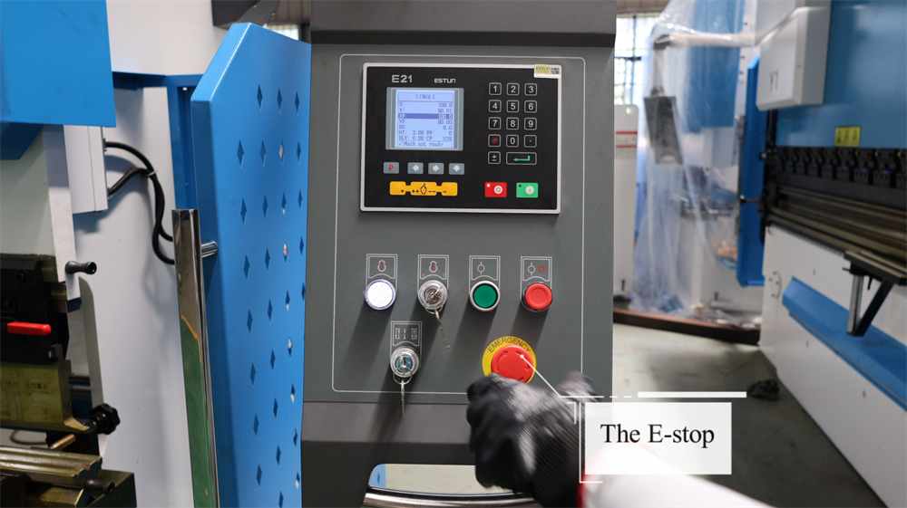
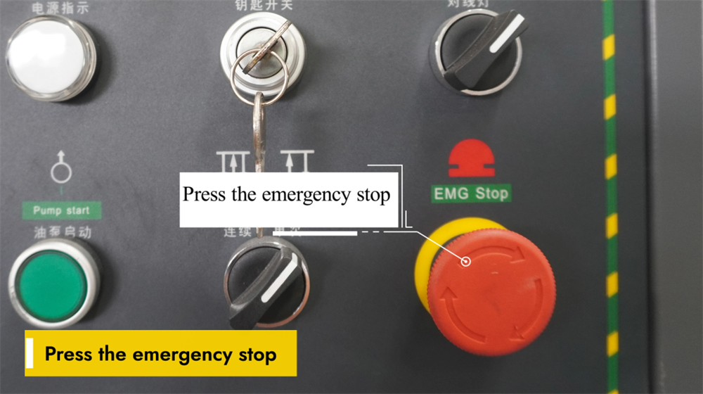
E21 NC pres bükme makinesinin çalışması sırasında ekipmanda arıza meydana gelmesi veya potansiyel güvenlik riskleri oluşması durumunda acil durdurma düğmesine hemen basın. Bu işlem, makinenin elektrik kaynağını anında keserek tüm hareketleri durdurur ve operatörün güvenliğini sağlar. Herhangi bir bükme işlemine başlamadan önce, acil durdurma düğmesinin her zaman kolayca erişilebilir ve engellenmemiş olduğundan emin olun. Düğmeyi düzenli olarak kontrol ederek işlevsel olduğunu ve herhangi bir kalıntından arındırıldığını doğrulayın. Acil durdurma düğmesi aktive edildikten sonra, makineyi yeniden başlatmadan önce temel sorunu tamamen tespit edin ve çözün. Bu güvenlik özelliğinin doğru kullanımı, çalışma ortamındaki riskleri en aza indirir ve genel operasyonel güvenliği artırır.
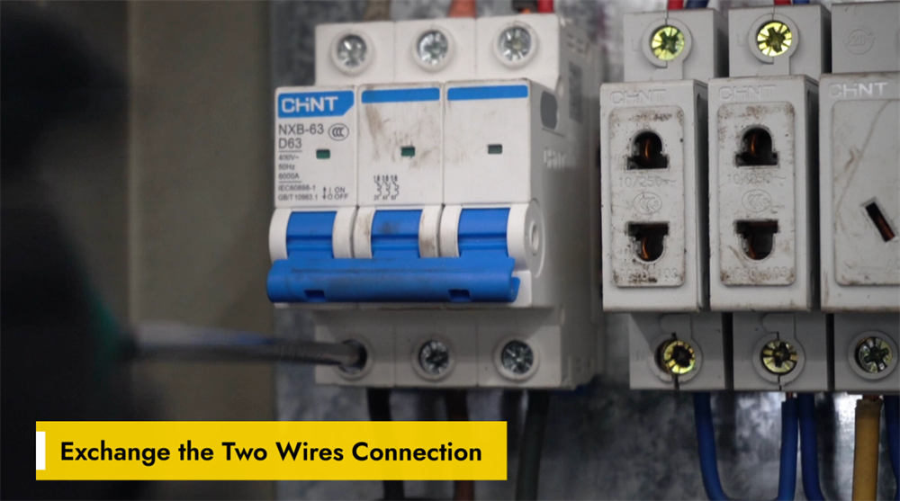
İki Kabloyu Değiştirerek Kablolama Hatasının Düzeltilmesi
Yanlış kablolama, E21 NC pres bükme makinesinin arka ölçüm sistemi (backgauge) veya çenesinin (ram) hareket yönünde arızalara neden olabilir ya da sistemin anormal tepkiler vermesine yol açabilir. Arka ölçüm sistemi veya çene yanlış yönde hareket ediyorsa, basit bir çözüm olarak motor veya kontrol panelindeki iki kablo bağlantısını değiştirmektir. Bu ayar, motorun faz sırasını tersine çevirerek normal işlevi geri kazandırır. Herhangi bir kablolama değişikliği yapmadan önce makinenin elektrik şalterini kapatın ve elektriksel güvenlik risklerini önlemek için kablolama şemasına başvurun. Kabloları değiştirdikten sonra makineyi yeniden başlatın ve arka ölçüm sistemi ile çenenin hareketini test ederek doğru çalıştığını doğrulayın. Bu hızlı sorun giderme yöntemi, operasyonel verimliliği korumaya ve plansız duruş sürelerini en aza indirmeye yardımcı olur.
Adım 2: Makine Açma İşlemi
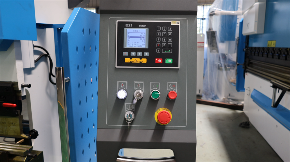
E21 NC Pres Bükme Makinesinin Açılması
E21 NC bükme presini çalıştırmadan önce makinenin kararlı bir güç kaynağına bağlı olduğunu doğrulayın. Ana güç anahtarını elektrik panosunda (genellikle makinenin yan veya arka tarafında) bulun ve "AÇIK" konumuna getirin; ardından sistemin başlatılmasını bekleyin. Sistem kullanıma hazır hâle geldiğinde kontrol paneli başlangıç bilgilerini gösterecektir; herhangi bir hata mesajı veya uyarı bildirimi olup olmadığını kontrol panelinde kontrol edin. Panelde herhangi bir anormallık görülmemişse, gerekli bükme parametrelerini ayarlamaya geçebilirsiniz. Kazaları önlemek için makinenin elektrik bileşenleriyle çalışırken her zaman elektrik güvenlik kurallarına uyun.
Hidrolik Yağ Pompasının Doğru Şekilde Başlatılması
Hidrolik yağ pompasını çalıştırmak, E21 NC pres bükme makinesini işletmenin ilk adımıdır. Güç kaynağının kararlı olduğundan ve makinenin doğru şekilde bağlandığından emin olduktan sonra, hidrolik sistemi devreye sokmak için kontrol panelindeki yağ pompası başlatma düğmesine basın. Sabit bir uğultu, pompasının sorunsuz çalıştığını gösterir; çalıştırma sırasında herhangi bir anormal ses veya titreşim olup olmadığını dinleyin. Herhangi bir bükme işlemi gerçekleştirmeden önce, pompaya sistemin tamamında hidrolik yağı eşit şekilde dolaştırması için yeterli zaman verin. Yağ pompasının doğru şekilde başlatılması, sabit hidrolik basıncı, sorunsuz bükme performansı ve makinenin uzun vadeli güvenilirliğini sağlar.
Acil Durdurma Anahtarını Serbest Bırakma
E21 NC bükme makinesini çalıştırmadan önce acil durdurma anahtarının doğru şekilde serbest bırakıldığını doğrulayın. Bu anahtar, bir acil durumda makinenin tüm işlemlerini anında durduran temel bir güvenlik özelliğidir. Anahtarı serbest bırakmak için saat yönünde çevirin; anahtar dışarı çıkana kadar çevirin, bu da sistemin yeniden etkinleştirildiğini gösterir. Anahtar serbest bırakıldıktan sonra kontrol panelinde herhangi bir hata mesajı olup olmadığını kontrol edin ve gerekirse sistemi sıfırlayın. Herhangi bir işlem başlatmadan önce makinenin güvenli ve çalıştırılmaya hazır bir durumda olduğunu her zaman doğrulayın. Acil durdurma anahtarının doğru şekilde kullanılması, işyeri güvenliğini sağlar ve plansız çalışma kesintilerini en aza indirir.
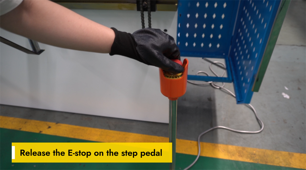
Ayak Pedalindeki Acil Durdurma (E-Stop) Anahtarının Serbest Bırakılması
E21 NC pres bükme makinesinin çalıştırılmasını sürdürmek için ayak pedalındaki acil durdurma (E-dur) düğmesi serbest bırakılmalıdır. Öncelikle E-dur düğmesinin basılı olup olmadığını kontrol edin; eğer basılıysa, sıfırlamak için saat yönünde döndürün. Daha sonra ayak pedalının doğru konumda olduğunu ve herhangi bir engelden arındırıldığını doğrulayın; ardından sistemin doğru şekilde tepki verdiğini onaylamak için pedala hafifçe basın. Makine çalışmazsa, tüm güvenlik kilitlemelerini kontrol edin ve gerekirse denetleyiciyi sıfırlayın. E-dur düğmesinin doğru şekilde serbest bırakılması, makinenin sorunsuz çalışmasını sağlar ve sac metal bükme süreçlerinde ölü zamanı azaltır.
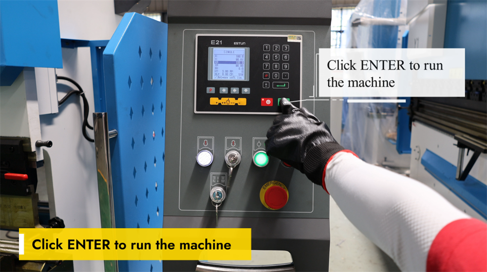
ENTER Tuşuyla Pres Bükme Makinesinin Çalıştırılmasına Başlama
ENTER tuşuna basmak, E21 NC pres bükme makinesini devreye sokar ve önceden programlanmış bükme sırasını başlatır. ENTER tuşuna basmadan önce, bükme açısı, arka ölçüm konumu ve hidrolik basınç ayarları dahil olmak üzere tüm parametrelerin doğru şekilde programlandığını doğrulayın. Doğrulama tamamlandıktan sonra ENTER tuşuna basmak, makinenin bükme işlemini gerçekleştirmesini sağlar. Operatörler, işlem boyunca sorunsuz çalışmayı sağlamak ve bükme hassasiyetini korumak için tüm süreci izlemelidir. Hareketli parçalardan ellerin uzak tutulması ve kişisel koruyucu ekipmanların takılması gibi kritik güvenlik önlemleri her zaman uygulanmalıdır. ENTER tuşunun doğru kullanımı, operasyonel verimliliği artırır, üretim hatalarını azaltır ve metal imalatında tutarlı bükme doğruluğunu sağlar.
Adım 3: Çalışma Modlarının Açıklaması
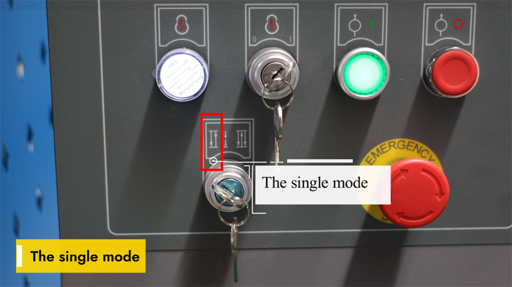
E21 Sisteminde Tekli Mod
E21 NC bükme makinesinin Tek Modu, operatörlerin bireysel bükme adımlarını birer birer manuel olarak gerçekleştirmesine olanak tanır. Bu mod, küçük parti üretim ve özel bükme görevleri için idealdir; çünkü her bireysel işlem üzerinde maksimum esneklik ve hassas kontrol sağlar. Operatörler, her adımı bağımsız olarak çalıştırmadan önce bükme açısını, arka ölçüm konumunu ve piston stroku sınırlarını ayarlayabilirler. Sistem, işlem sırasında gerçek zamanlı parametre ayarlamalarına izin verirken doğru performansı garanti eder. Tek Mod, özellikle prototip geliştirme ve tek seferlik özel projeler için oldukça değerlidir; çünkü karmaşık programlamaya gerek kalmadan yüksek bükme hassasiyeti sunar. Bu modu ustalaşmak, saclı metal bükme süreçlerinde işlemsel verimliliği önemli ölçüde artırabilir ve hataları en aza indirebilir.
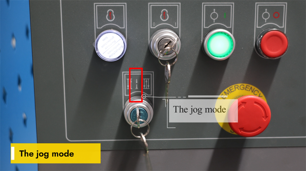
E21 Sisteminde Jog Modu
E21 NC pres bükme makinesinin Jog Modu, operatörlerin damıtma hareketini manuel olarak kontrol etmesine olanak tanıyarak hassas konumlandırmayı sağlar. Bu mod, özellikle kalıp kurulumu, bükme açılarının test edilmesi ve seri üretim başlamadan önce konum doğruluğunun sağlanmasında kullanılır. Jog butonuna basıldığında damıtma adım adım hareket eder; bu da operatörlere bükme derinliği ve parça hizalaması üzerinde tam kontrol imkânı sunar. Jog Modu, parametrelerin ince ayarlanması, üretim hatalarının azaltılması ve iş verimliliğinin artırılması açısından özellikle faydalıdır. Operatörler, damıtma pozisyonunun aşırı ayarlanmasını önlemek için bu modu dikkatli bir şekilde kullanmalıdır. Jog Modu fonksiyonunu ustalaşmak, makinenin doğruluğunu artırır ve tutarlı bükme sonuçları elde edilmesini sağlar; bu nedenle makine kurulumu ve kalibrasyonu için temel bir özelliktir.
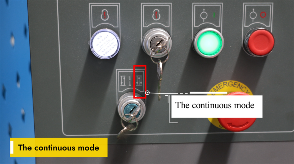
E21 Sisteminde Sürekli Mod
E21 NC pres bükme makinesinin Sürekli Çalışma Modu, kesintisiz bükme işlemlerini mümkün kılar ve seri üretim senaryolarında verimliliği önemli ölçüde artırır. Bu mod etkinleştirildiğinde makine, her iş parçası için operatörün işlemi yeniden başlatmasına gerek kalmadan önceden programlanmış bükme sırasını otomatik olarak tekrarlar. Bu mod, yüksek hacimli sac metal imalatı için idealdir; çünkü plansız duruş sürelerini azaltır ve genel üretkenliği artırır. Sürekli Çalışma Modu etkinleştirilmeden önce operatörler, bükme doğruluğu ve tutarlılığı açısından doğru takımların hizalanması ile iş parçalarının doğru konumlandırılması gerektiğini sağlarlar. Ayrıca makinenin çalışma sırasında düzenli izlenmesi, bileşenlerin yanlış hizalanması veya üretim hatalarının önlenmesi açısından hayati öneme sahiptir. Sürekli Çalışma Modu’nun etkili kullanımı, üreticilerin daha hızlı üretim döngüleri elde etmelerini ve tutarlı bükme kalitesi sağlamalarını sağlayarak pres bükme makinesinin genel işletme performansını optimize eder.
Adım 4: Sistem İşletimi ve Kontrolü
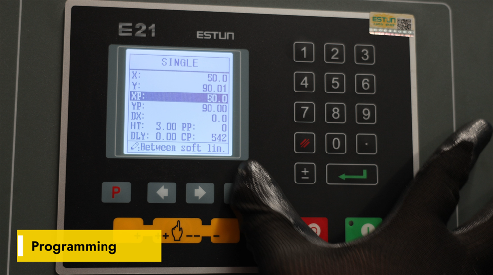
E21 NC Pres Bükme Makinesi İçin Programlama Talimatları
E21 NC bükme presi, verimli sac metal bükme işlemleri için tasarlanmış basit ancak güçlü bir programlama arayüzüne sahiptir. Operatörler, bükme açılarını, arka ölçüm pozisyonlarını ve çok adımlı bükme sıralarını dijital kontrol paneli üzerinden ayarlayabilirler. Sistem, çok adımlı programlamayı destekler; bu sayede operatörler karmaşık imalat projeleri için birden fazla bükme prosedürünü kaydedebilirler. Makinenin performansını optimize etmek amacıyla malzeme parametrelerinin doğru girilmesi, uygun takım seçimi ve düzenli sistem kalibrasyonu sağlanmalıdır. E21 kontrolörü, kullanıcı dostu bir çalışma deneyimi sunar ve bu nedenle küçük ile orta ölçekli metal imalat atölyeleri için ideal bir seçenektir. E21 NC bükme presinin programlamasını ustalaşmak, üretim verimliliğini ve bükme hassasiyetini önemli ölçüde artırırken üretim hatalarını ve malzeme israfını azaltır.
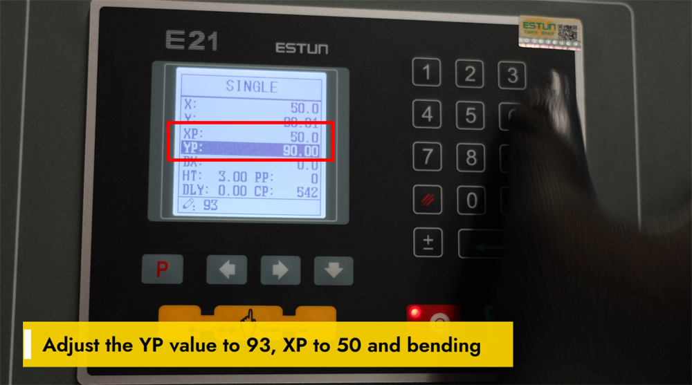
Bükme İşlemleri İçin YP=93 ve XP=50 Ayarlanması
E21 NC bükme makinesiyle hassas bükme sonuçları elde etmek için YP ve XP parametrelerinin doğru ayarlanması gerekir. Hassas baskı ünitesi konumlandırmasını sağlamak ve dolayısıyla bükme derinliğini ile tutarlılığı doğrudan etkilemek için YP değerini 93 olarak ayarlayın. Hassas iş parçası hizalaması için arka ölçüm (backgauge) konumunu optimize etmek amacıyla XP değerini 50 olarak ayarlayın. Bu iki parametrenin doğru kalibrasyonu, bükme doğruluğunu önemli ölçüde artırır, malzeme kaybını azaltır ve genel operasyon verimliliğini geliştirir. Bu ayarların düzenli olarak kontrol edilmesi ve ince ayarlanması, makinenin performansını daha da artırabilir; böylece sac metal imalatında minimum hata ile yüksek kaliteli bükümler sağlanır.
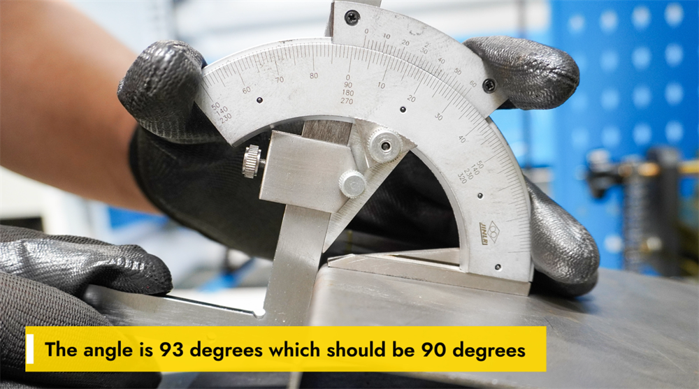
Hedef Açının 93 Derece Olarak Kalibre Edilmesi
Gerçek bükme açısı hedeflenen 90 derece yerine 93 derece ise, doğruluğu artırmak için parametre ayarlamaları gerekmektedir. Bu sapma, genellikle malzemenin geri yaylanma (springback) etkisi, yanlış burun (punch) ve kalıp (die) seçimi veya yetersiz hidrolik basınç ayarlarından kaynaklanır. Açının düzeltilmesi amacıyla operatörler makinenin tonajını artırabilir, daha dar açıklıklı bir V-kalıp kullanabilir veya malzemenin geri yaylanmasını telafi etmek için aşırı bükme (over-bending) teknikleri uygulayabilir. Ayrıca, arka ölçüm (backgauge) konumunun kontrol edilmesi ve pres freninin tamamıyla kalibre edilmesi, kesin 90 derecelik hedef açıya ulaşmada yardımcı olur. Malzeme kalınlığının ve bükme parametrelerinin düzenli olarak kontrol edilmesi, tutarlı üretim sonuçları elde edilmesini sağlar ve hataları en aza indirir. Doğru parametre ayarlamaları yalnızca bükme doğruluğunu değil, aynı zamanda makinenin genel işlevsel verimliliğini de artırır.
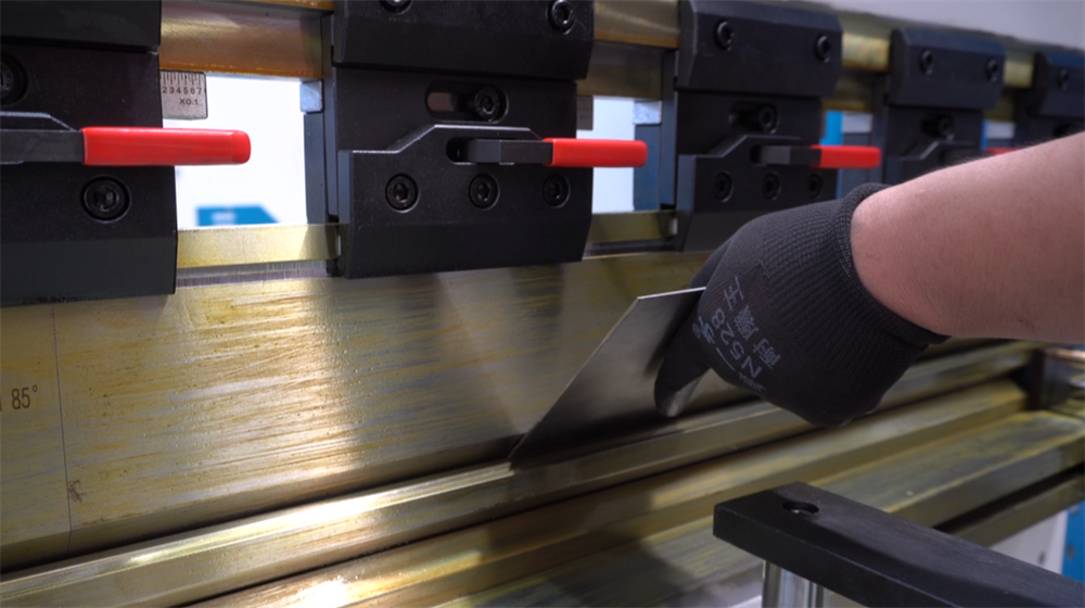
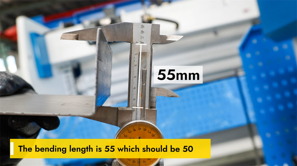
Bükme Uzunluğunun Doğruluğunun Ayarlanması
Gerçek bükme uzunluğu 55 mm iken istenen uzunluk 50 mm ise, hassas bükme elde etmek için ayarlamalar yapılması gerekir. Öncelikle E21 NC kontrolöründeki ayarları kontrol edin ve arka ölçüm (backgauge) konumunun doğru şekilde kalibre edildiğini doğrulayın. Kontrol sistemindeki bükme parametrelerini ayarlayın ve boyutsal sapmaları en aza indirmek için punch ve kalıp hizalamasını kontrol edin. Gerekirse iş parçasının konumunu ince ayarlayıp doğrulama amacıyla test bükme işlemlerini gerçekleştirin. Arka ölçüm (backgauge) ve hidrolik sisteminin düzenli bakımı da tutarlı bükme sonuçlarının korunmasına yardımcı olur. Bükme uzunluğunun doğru şekilde ayarlanması, üretimde hassasiyeti sağlar, malzeme israfını azaltır ve genel üretim verimliliğini artırır.
Adım 5: Sistem Kalibrasyonu Süreci
E21 Pres Bükme Makinesi İçin Y-Ekseni Kalibrasyonu
E21 NC bükme makinesinin Y-ekseni kalibrasyonu, metal imalatında doğru bükme derinliği ve tutarlı sonuçlar elde etmek için hayati öneme sahiptir. Doğru kalibrasyon, çene hareketini önceden programlanmış bükme parametreleriyle hizalar ve boyutsal sapmaları ile malzeme kaybını önler. Y-eksenini kalibre etmek için E21 kontrol birimine erişin, Y-ekseni ayarları arayüzüne gidin ve takılı olan kalıp setine ve iş parçası malzemesinin kalınlığına göre doğru referans değerlerini girin. Değerleri girdikten sonra test bükme işlemleri gerçekleştirin ve sonuçları ölçerek gerekli durumlarda ayarları hassas şekilde iyileştirin. Düzenli Y-ekseni kalibrasyonu, bükme hassasiyetini korur ve takımların kullanım ömrünü uzatır; böylece tüm işlemlerde yüksek kaliteli bükme sonuçları sağlanır. Kalibrasyon sırasında her zaman üreticinin talimatlarına uygun hareket ederek makinenin en iyi performansını sağlamak ve bileşenlerde yanlış hizalamayı önlemek gerekir.
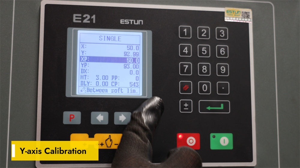
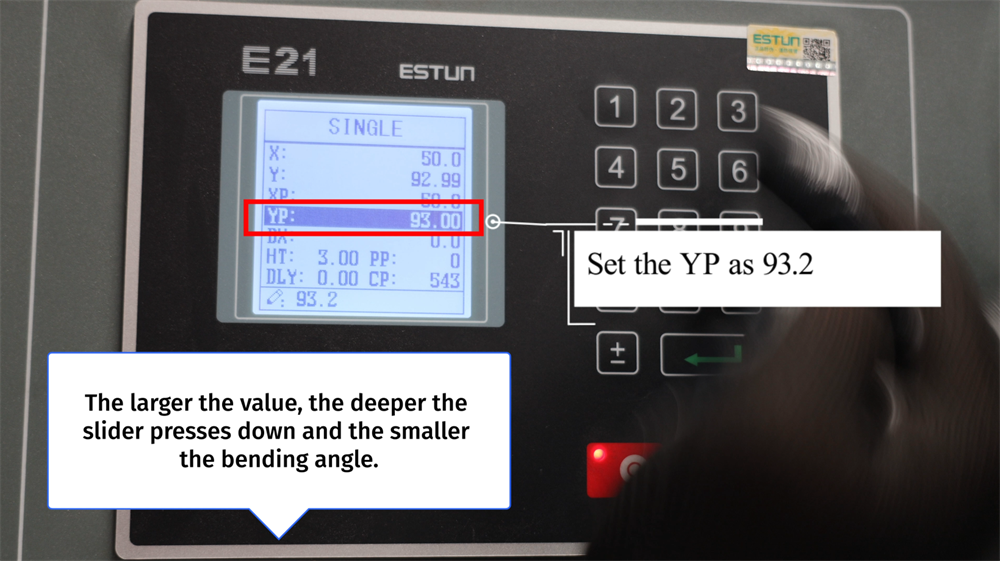
Hassas Bükme İçin YP Ayarının Hassas İyileştirilmesi
YP değerinin 93,2 olarak ayarlanması, bükme işlemi sırasında kaydırıcının aşağı doğru hareket miktarını belirler. Daha yüksek bir YP değeri, kaydırıcının iş parçasına daha derin baskı uygulamasına olanak tanır ve bu da daha küçük bir bükme açısına neden olur. Buna karşılık, daha düşük bir YP değeri kaydırıcının aşağı yönlü hareketini sınırlandırır ve daha büyük bir bükme açısı üretir. YP değerinin doğru ayarlanması, hassas ve tutarlı bükme sonuçlarının elde edilmesini sağlar; malzeme israfını en aza indirir ve operasyonel verimliliği artırır. Operatörler, istenen bükme açısına ve iş parçası malzemesinin kalınlığına göre YP ayarını ince ayarlamalıdır. Sac metal imalatında yüksek kaliteli bükümlerin korunması için YP değerinin düzenli kalibrasyonu zorunludur.
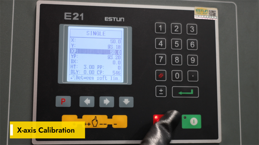
X Ekseni Kalibrasyon Talimatları
Doğru X ekseni kalibrasyonu, E21 NC pres bükme makinesinde arka ölçüm (backgauge) konumunun doğruluğunu sağlamak için kritik öneme sahiptir; bu da hassas sac metal bükme işlemlerinde temel bir faktördür. X eksenini kalibre etmek için E21 kontrolöründe parametre ayarları arayüzüne erişin ve arka ölçümün gerçek fiziksel konumunu girin. Arka ölçüm ile belirlenen bükme çizgisi arasındaki mesafeyi doğrulamak için yüksek hassasiyetli bir ölçüm aracı kullanın; ardından gerekirse parametreleri ayarlayıp ayarları kaydedin. Düzenli X ekseni kalibrasyonu, iş parçalarında boyutsal hataları önler ve bükme sonuçlarının tutarlılığını artırır. Takım değişikliği veya makine bakımı yapıldıktan sonra her zaman X ekseni kalibrasyonunu yeniden kontrol edin. İyi kalibre edilmiş bir X ekseni, operasyonel verimliliği artırır, tekrar işlenmeyi azaltır ve yüksek hassasiyetli metal bükme işlemlerini sağlar.
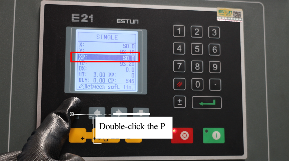
"P" Tuşuna Çift Tıklayın ve Kurulum Moduna Girin
"P" tuşuna çift tıklamak, E21 NC bükme makinesinin programlama ve kurulum moduna girmek için kritik bir adımdır. Bu işlem, operatörlerin yaklaşan işlemler için bükme açılarını, arka ölçüm konumlarını ve piston stroku parametrelerini verimli bir şekilde ayarlamasını sağlar. Kurulum moduna girdikten sonra operatörler, tüm gerekli parametreler için sayısal değerleri girebilir ve ayarları onaylayarak hassas bükme işlemlerini garanti altına alabilirler. Bu fonksiyon iş akışını kolaylaştırır; makine kurulum süresini azaltır ve üretim hatalarını en aza indirir. En iyi üretim sonuçlarını elde etmek için bükme işlemine başlamadan önce tüm parametrelerin doğru girildiğinden her zaman emin olun. Bu basit adımı ustalaşmak, E21 NC kontrolörünün kullanımını kolaylaştırır ve daha doğru ve verimli metal bükme işlemlerini sağlar.
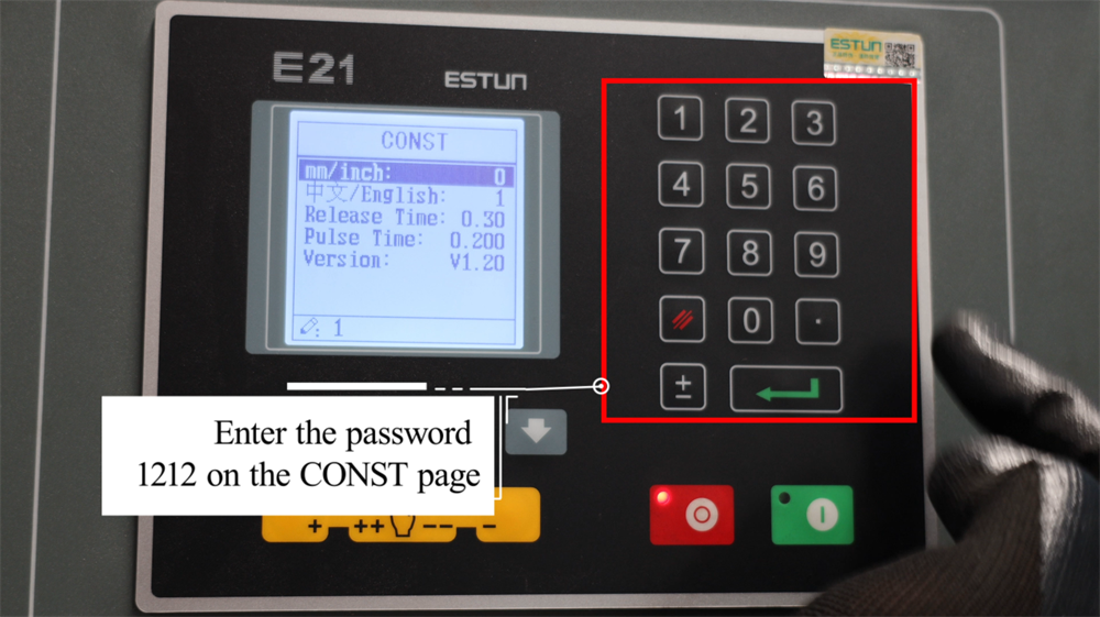
CONST Arayüzünde Şifreyi 1212 olarak girin
E21 NC bükme makinesinin gelişmiş ayar seçeneklerine erişmek için, kontrolörün ekranındaki CONST arayüzüne gidin. Şifre istendiğinde, kısıtlı yapılandırma parametrelerini kilidini açmak için 1212 girin. Bu erişim, operatörlerin temel sistem parametrelerini ayarlamasına, bükme hassasiyetini optimize etmesine ve üretim gereksinimlerine özel olarak işlem ayarlarını değiştirmesine olanak tanır. Erişim kısıtlamalarını önlemek için şifrenin doğru girilmesi kritik öneme sahiptir. Gelişmiş ayarlar kilidi açıldıktan sonra, parametreleri üretim hattınızın belirli sac metal bükme ihtiyaçlarına göre dikkatlice gözden geçirin ve yapılandırın. Herhangi bir ayarla ilgili emin değilseniz, resmi işletme kılavuzuna başvurun ya da teknik destek ekibine JUGAO ile iletişime geçin.
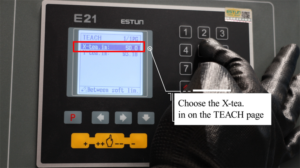
ÖĞRETİM Sayfasında Uygun X-Tea Seçimi
E21 kontrolörünün ÖĞRET sayfasında uygun X-Çay seçeneğini seçmek, operasyonel ihtiyaçlarınıza uygun özelleştirilmiş bir öğrenme deneyimi elde etmenizi sağlar. Her X-Çay seçeneği, E21 sisteminin farklı yönleriyle ilgili kapsamlı içgörüler sunacak şekilde tasarlanmıştır; bu da operatörlerin temel operasyonel kavramları ustalaşmasını kolaylaştırır. Temel bir operasyon kılavuzundan yararlanmak isteyen bir başlangıç seviyesi kullanıcı olursanız ya da ileri düzey teknik ayrıntılara ihtiyaç duyan deneyimli bir profesyonel olursanız, ÖĞRET sayfası tüm seviyelere uygun yapılandırılmış öğrenme seçenekleri sunar. Mevcut X-Çay seçimlerini gözden geçirin, içeriklerini ve özelliklerini karşılaştırın ve öğrenme hedeflerinize en çok uyum sağlayan seçeneği belirleyin. Açık talimatlar ve iyi organize edilmiş içerikle X-Çay seçenekleri, temel operasyonel bilgileri hızlıca kavramanızı ve bunları gerçek dünya üretim senaryolarında etkili bir şekilde uygulamanızı sağlar.
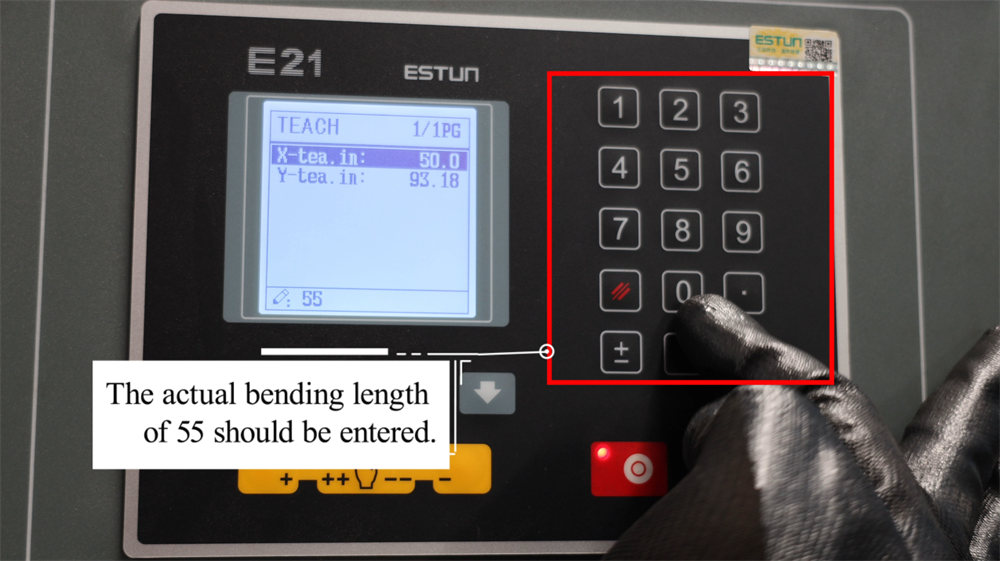
Tam Gerekli Eğme Uzunluğunu Girin
Gerçek gerekli bükme uzunluğunun doğru şekilde girilmesi, E21 NC bükme makinesi için kritik bir kurulum adımıdır; çünkü bu işlem doğrudan hassas bükme sonuçlarını garanti eder. Üretim gereksinimi 55 mm bükme uzunluğu ise, kontrol sistemine değer olarak 55 girilmelidir. Bu, arka ölçüm (backgauge) konumunun ve tüm ilgili bükme parametrelerinin iş parçasının boyutsal gereksinimleriyle uyumlu olmasını sağlar ve nihai bükülmüş ürünün hatalı çıkmasını önler. Doğru parametre girişi, malzeme kaybını en aza indirir ve üretim verimliliğini artırır. Bükme işlemine başlamadan önce girilen değerleri her zaman doğrulayın; böylece iş parçasının yanlış hizalanması önlenir. E21 sisteminde doğru veri girişi, tutarlı bükme hassasiyeti elde etmek ve pres bükme makinesinin genel verimini optimize etmek açısından hayati öneme sahiptir.
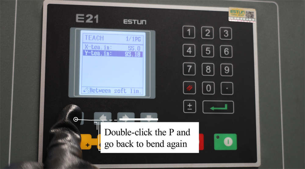
Bükme İşlemlerini Yeniden Başlatmak İçin "P" Tuşuna Çift Tıklayın
E21 NC bükme presinin çalışması sırasında operatörler, kontrolördeki "P" düğmesine çift tıklayarak bükme işlemini hızlıca devam ettirebilir. Bu fonksiyon, iş parçasını yeniden konumlandırmak veya önceden programlanmış bükme sırasına devam etmeden önce parametreleri ince ayarlamak gerektiğinde özellikle yararlıdır. "P" düğmesine çift tıklandığında makine, otomatik olarak son bükme konumuna geri döner ve böylece sorunsuz ve verimli bir üretim akışı sağlanır. Bu özellik, operasyon hızını ve bükme doğruluğunu artırarak bireysel bükme adımları arasındaki ölü süreyi azaltır. Bu fonksiyonu ustalaşmak, sac metal şekillendirme süreçlerinde daha yüksek verimlilik ve hassasiyet sağlar. İşletmeye devam etmeden önce her zaman iş parçası ve baskı kolu konumlarını yeniden kontrol ederek yanlış hizalama ve üretim hatalarından kaçının.
Adım 6: Pratik Üretim Gösterimi
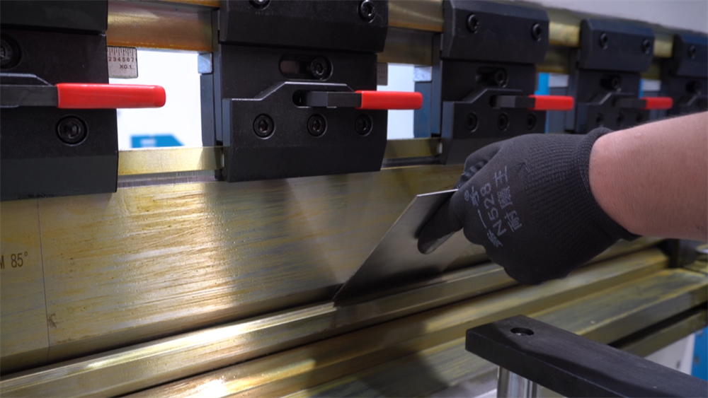
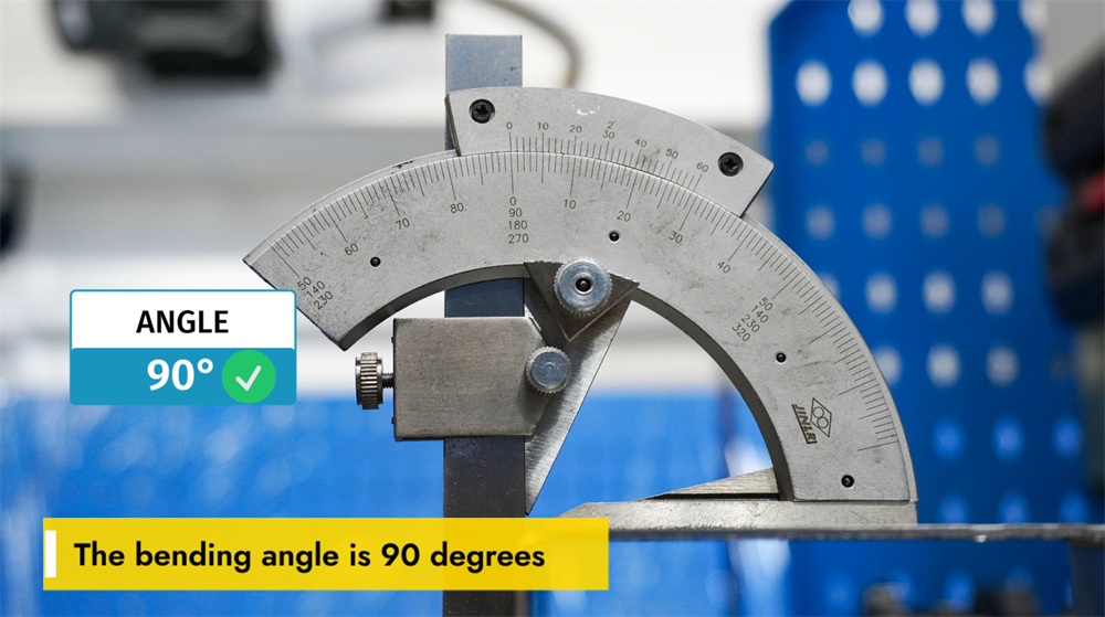
90 Derecelik Bükme Açısı Elde Etmek
90 derecelik bükme açısı, metal imalatında en yaygın gereksinimlerden biridir; bu açının tutarlı ve hassas bir şekilde elde edilmesi, iş parçası malzemesinin kalınlığı, kalıp seçimi ve pres freni parametre ayarları gibi birkaç temel faktöre bağlıdır. Doğru V-kalıp genişliği ve burun yarıçapı, bükme doğruluğunu korumada kritik bir rol oynar. Ayrıca, bükme kuvveti ve arka ölçüm (backgauge) konumunun ayarlanması, çok sayıda iş parçası üzerinde 90 derecelik bükme işlemlerinin tekrarlanabilirliğini sağlar. Operatörler ayrıca malzemenin elastik geri dönüşünü (springback) dikkate almalı ve açısal sapmaları önlemek için uygun telafi tekniklerini uygulamalıdır. E21 sistemi gibi NC kontrollü bir pres freni kullanmak, yüksek hacimli üretim süreçlerinde tutarlı bükme sonuçlarının sağlanmasına yardımcı olur ve hataları azaltarak işletme verimliliğini artırır. Doğru sistem kalibrasyonu ve takım seçimi, her seferinde mükemmel bir 90 derecelik bükme elde etmenin temel taşını oluşturur.
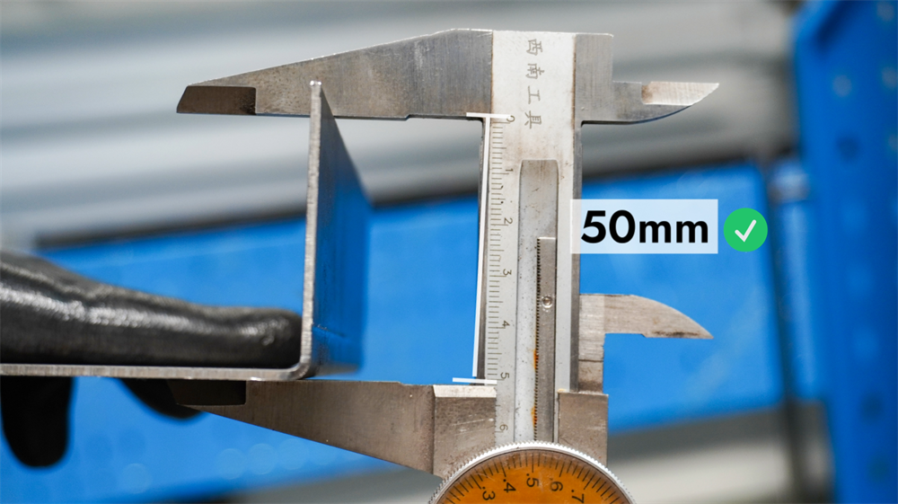
E21 Sisteminde Bükme Uzunluğunun Anlaşılması
E21 NC bükme presinin bükme uzunluğu, tek bir işlemde bükülebilen sac metalin maksimum uzunluğunu ifade eder; bu uzunluk makinenin çalışma masası boyutu ve monte edilen takımlandırma konfigürasyonu tarafından belirlenir. Üretim gereksinimlerine göre bükme uzunluğunun doğru şekilde ayarlanması, doğru bükme sonuçlarının elde edilmesini sağlar, malzeme kaybını en aza indirir ve takımların aşırı yüklenmesini önler. Operatörler, her zaman makinenin teknik özelliklerine başvurmalı, uygun burun ve kalıp seçmeli ve hassas sonuçlar elde etmek için arka ölçüm (backgauge) konumunu gerekli bükme uzunluğuna göre ayarlamalıdır. Makinenin bükme uzunluğu kapasitelerine dair net bir anlayış, sac metal imalatında üretim verimliliğini optimize etmek ve tutarlı bükme doğruluğu sağlamak için temel bir gerekliliktir.
7. Adım: Doğru Kapatma Prosedürü
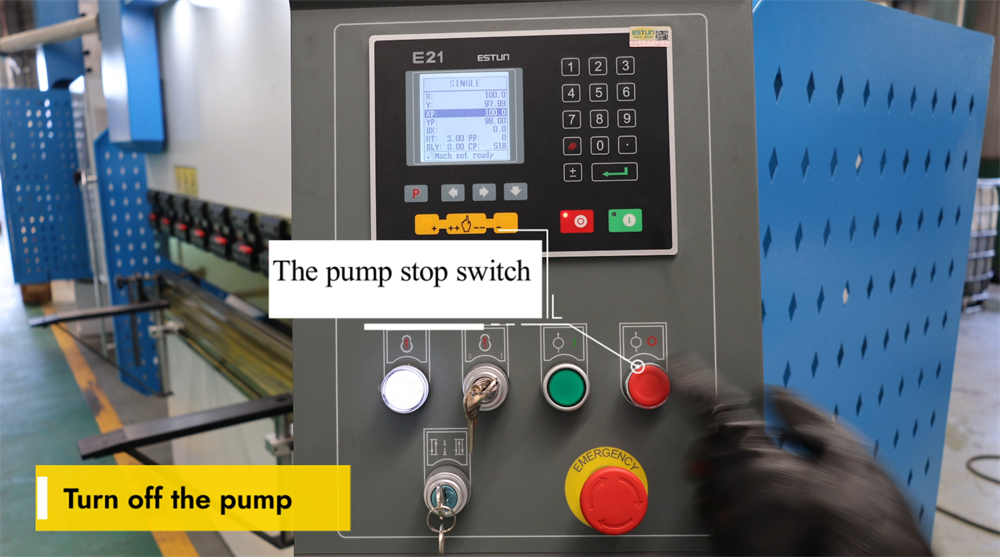
Pompa Durdurma Anahtarını Çalıştırma
Pompa durdurma anahtarı, E21 NC bükme pres sisteminin temel bir bileşenidir ve operatörlerin makine kullanılmadığında hidrolik pompayı güvenli bir şekilde kapatmalarını sağlar. Bu anahtara basmak, hidrolik pompayı anında durdurur; bu da gereksiz enerji tüketimini önler ve hidrolik sistemin parçalarındaki aşınmayı azaltır. Bükme işlemlerinin tamamı sonrasında hidrolik pompayı kapatmak, makinenin ömrünü uzatmak ve işyeri güvenliğini sağlamak açısından hayati öneme sahiptir. Sonraki işlemler için pompayı yeniden başlatmadan önce, sistemin arızalanmasını önlemek amacıyla anahtarın doğru şekilde etkinleştirildiğinden emin olun. Düzenli bakım ve doğru kapatma prosedürlerine uyulması, bükme presinin zaman içinde en iyi performansını korumasına yardımcı olur.
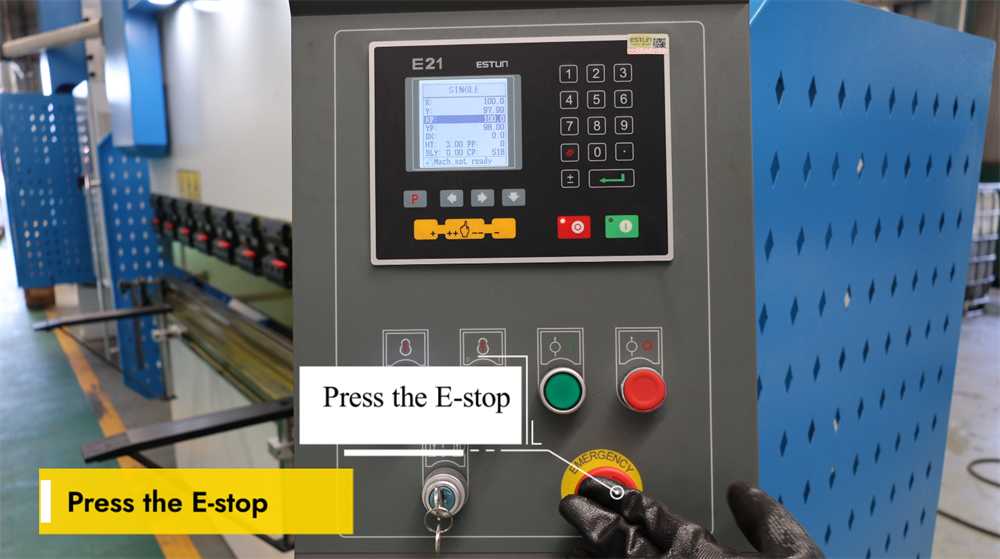
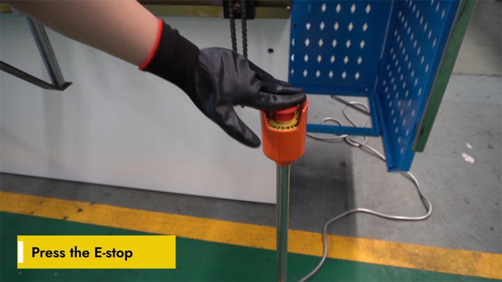
Güvenlik Amaçlı Acil Durdurma (E-Stop) Fonksiyonunun Etkinleştirilmesi
Acil durdurma (E-durdurma) düğmesi, E21 NC bükme makinesinde kritik bir güvenlik özelliğidir. Bu düğmeye basıldığında makinenin tüm işlemleri anında durur ve böylece acil durumlarda olası işyeri tehlikeleri etkili bir şekilde önlenir. Operatörler, ani ekipman arızaları, beklenmedik iş parçası hareketleri veya diğer herhangi bir potansiyel güvenlik riski durumunda E-durdurma düğmesini devreye sokmalıdır. E-durdurma düğmesi devreye girdikten sonra makine tamamen sıfırlanmalı ve temeldeki sorun çözüldükten sonra işlem yeniden başlatılabilir. E-durdurma düğmesi, işlevsel olduğundan ve engellerden arındığından emin olmak için düzenli olarak kontrol edilmelidir. Bu güvenlik özelliğinin doğru kullanımı, işyeri güvenliğini artırır ve hem operatörü hem de ekipmanı hasarlara karşı korur. E21 NC bükme makinesini çalıştırırken her zaman resmi güvenlik yönergelerine uyun.
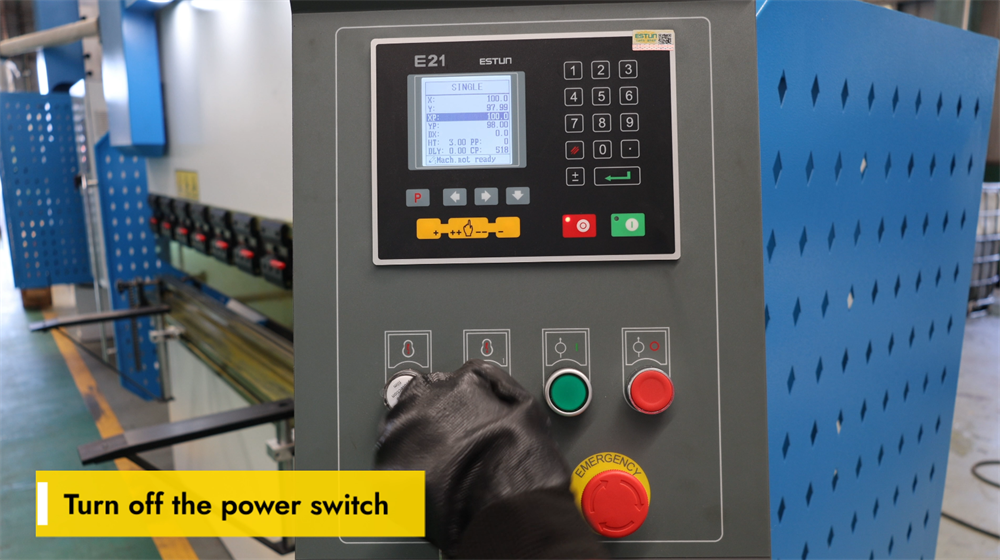
E21 NC Bükme Makinesini Doğru Şekilde Kapatma
Herhangi bir bakım işlemi gerçekleştirmeden veya E21 NC bükme makinesini kapatıp günlük üretim işlemini tamamlamadan önce ana güç şalterini doğru şekilde kapatmak hayati derecede önemlidir. Ana güç şalterini kontrol panelinde bulun ve "KAPALI" konumuna getirin. Bu adım, bakım sırasında kazara makine çalıştırılmasını veya elektrik arızalarını önlemek amacıyla elektriksel güvenliği sağlar. Herhangi bir ayarlama, inceleme veya bakım işlemi gerçekleştirmeden önce makinenin tamamen kapatıldığını her zaman doğrulayın. Doğru kapatma prosedürlerine uyulması, makinenin kullanım ömrünü uzatır ve tüm operatörlerin güvenliğini garanti eder. Ayrıca, uzun süreli kullanımdan kaçınma dönemlerinde güç kaynağını kesmek enerji tüketimini azaltır ve makinenin elektronik bileşenlerini olası gerilim dalgalanmalarına karşı korur.
Sonuç
Bu E21 sistem işletme kılavuzundaki talimatlara uyarak, E21 kontrol sistemiyle donatılmış bir NC pres bükme makinesinin nasıl işletileceğine dair kapsamlı bir anlayışa sahip olmalısınız. Hidrolik yağ doldurma, elektrik bağlantısı, sistem kalibrasyonu ve pratik bükme işlemlerini içeren temel adımları öğrenmek, pres bükme makinenizin üretimde verimliliğini ve hassasiyetini en üst düzeye çıkarmayı sağlayacaktır. Makinenin doğru şekilde kurulması ve düzenli olarak kalibre edilmesi, tutarlı ve doğru bükümlerin sağlanmasında ve üretim ortamında ekipmanın performansının optimize edilmesinde kritik öneme sahiptir. Bu işletme bilgisi, yalnızca yüksek kaliteli sac metal imalat sonuçları elde etmenize değil, aynı zamanda makinenin ömrünü uzatmanıza ve işletme hatalarından kaynaklanan plansız duruş sürelerini azaltmanıza da yardımcı olacaktır.
İşletim sırasında herhangi bir sorunla karşılaşırsanız veya bu kılavuzdaki herhangi bir adımda daha fazla açıklama ihtiyacınız olursa, profesyonel teknik destek ekibimiz her zaman yardımcı olmak için sizinle birlikte olacaktır. E21 NC bükme makinesinizden en iyi performansı elde etmenizi sağlamak ve günlük operasyonlarınızın sorunsuz ilerlemesini desteklemek amacıyla kapsamlı satış sonrası hizmetler sunmayı taahhüt ediyoruz.
E21 sistemi hakkında daha ayrıntılı bilgiye ihtiyaç duyarsanız veya pres bükme makineleri ve diğer endüstriyel makinelerimizin tam ürün yelpazesi hakkında daha fazla bilgi edinmek isterseniz, resmi JUGAO web sitesini ziyaret etmenizi öneririz. Web sitemiz, detaylı ürün kılavuzları, video işlem eğitimleri ve teknik özellikler gibi ek kaynaklarla doludur; tüm bunlar, ekipmanınızdan maksimum verimi almanızı sağlamak amacıyla hazırlanmıştır. Herhangi bir soru veya destek talebi için lütfen web sitemizde yer alan iletişim bilgileri aracılığıyla doğrudan bizimle iletişime geçebilirsiniz.

