


The ESA S530 Punch and Die Setup System: A Complete Operational Guide
Table of Contents
1. Overview
2. How to Draw a New Punch
3. Punches Requiring Custom Drawing
4. Preset Punches Function
5. How to Draw a New Die
6. Dies Requiring Custom Drawing
7. Preset Dies Function
8. Frequently Asked Questions (FAQ)
9. Conclusion
1. Overview
In the field of industrial manufacturing, the efficient setup of punches and dies directly determines production efficiency and product precision—it not only boosts productivity but also ensures products meet high-quality standards. The ESA S530 Punch and Die Setup System (hereafter referred to as the "ESA S530 System") is specifically designed to streamline this process. By offering features such as custom drawing of punches/dies and preset parameter retrieval, it helps users optimize tool management.
Whether you are a novice in metalworking or a seasoned professional looking to refine your operational skills, mastering the ESA S530 System can significantly reduce equipment downtime and enhance the overall efficiency of production lines. Equipped with cutting-edge technology, the system supports seamless integration and precise tool management. Its intuitive interface not only lowers training costs but also effectively reduces errors during setup, ensuring consistent operation results.
2. How to Draw a New Punch
To custom-draw a new punch, follow these steps:
1. Access the Punch/Die List: Press the corresponding button to display the list of punches or dies. If the current display shows the die list, press the button again to switch to the punch list.

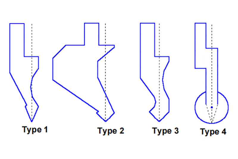
2. Select Punch Type: There are two ways to create a punch—full custom drawing, or using one of four preset punches with fixed parameters (adjusting parameters allows scaling and redrawing of the punch). If the required punch is similar to a preset type (sourced from the system’s built-in catalog), it is recommended to use the preset punch first to simplify the drawing process. If the punch shape falls outside the scope of preset options, full custom drawing is necessary.
3. Enter Parameter Settings: Press the "Settings" button to open the menu, then select based on your needs:
◦ "New Punch Drawing": Launch the full custom drawing mode;
◦ "Preset Type 1/2/3": Call up the corresponding preset punch type;
◦ "Preset Type 4": Call up the circular preset punch.
1. Input Punch Parameters: The system will pop up a parameter input window. Fill in the total height and effective height of the punch as shown in the on-screen diagram.
2. Access the Drawing Interface: After completing parameter input and type selection, the system will navigate to the drawing interface (the interface style automatically adjusts based on the selected punch type). Finally, click [Confirm] and press the [ENTER] key to start drawing.
3. Punches Requiring Custom Drawing
The dedicated interface for custom-drawn punches must be generated through the system’s drawing function (refer to the corresponding chapter in the operation manual for specific operations). The interface layout and functional division are as follows:
• Left Window: The core drawing area, used to display the punch drawing in real time;
• Right Window: The data input area, which dynamically switches based on the type of line being drawn and supports:
◦ Polar coordinate drawing data input;
◦ Vertex drawing data input;
◦ Arc drawing data input;
◦ Drawing specification instructions.
Key Drawing Rules and Steps
1. Drawing Direction and Positioning: Punches must be drawn in a counterclockwise direction, and note that the locator is on the right side of the punch.
2. Vertex Definition (Mandatory Step): Before using the punch drawing function, the punch vertex must be defined—the highlighted line when drawing starts is one of the two sides of the vertex. The definition process is as follows:
◦ Enter Length (l): Fill in the length of one side of the punch vertex, then press [ENTER] to confirm;
◦ Enter Tip Angle: Set the vertex angle to ensure shape precision, then press [ENTER] to confirm;
◦ Enter Chamfer (S): Add chamfer parameters to improve punch durability, then press [ENTER] to confirm;
◦ Enter Tip Radius (R): Specify the radius to optimize force distribution, then press [ENTER] to confirm;
◦ Enter Punch Load: Mark the maximum load capacity of the punch (unit: tons per meter), then press [ENTER] to confirm.
After completion, the system will automatically draw the vertex and generate the next line with the same length as the first side.
1. Specific Drawing Operations
◦ Basic Data Entry: First, fill in the vertex parameters in "Field 1" of the vertex data input window. Then specify the length of the second side (Line 11) and press [ENTER] to confirm;
◦ Angle Setting: The cursor will automatically jump to the "Angle Input Field (α)". Enter the relative angle of the next line, then press [ENTER]—the system will automatically draw the line and jump to "Line Length Input Field 1";
◦ Arc Drawing: To draw a curved line, press the [Arc] key. Enter the line length (l2) and depth (p1), then press [ENTER] to continue drawing. For subsequent lines, ensure angles and lengths are as close to actual measurements as possible to guarantee precision;
◦ Graphic Fine-Tuning: Use the direction keys to fine-tune angles (±1°) and lengths (±1mm)—use the left/right keys to adjust angles and the up/down keys to adjust lengths.
1. Data Correction Method
Incorrect entries can be corrected in real time during drawing. Navigate and modify using the following keys:
◦ Switch to the Previous Input Field: Alternate between the "Line Input Field (l)" and "Angle Input Field (α)";
◦ Jump to the Next Line: Directly switch to the "Length Input Field (l)" of the next line;
◦ Confirm and Jump: Press the [ENTER] key to alternate between the "Line Input Field (l)" and "Angle Input Field (α)" when jumping to the next field.
1. Common Error Recovery
A frequent error is forgetting to press [ENTER] after entering an angle (especially when using arrow keys to input angles). This causes the line length to be incorrectly entered into the angle field, leading to drawing deviations. In this case, press the corresponding key to return to the angle input field and re-enter the correct data.
2. Drawing Saving Process
After completing the drawing, press the "Save" button. Enter the punch name in the pop-up window (a combination of letters and numbers is allowed, e.g., using the punch code from the product catalog). After entering the name, click [Confirm] and press the [ENTER] key to complete the save.
4. Preset Punches Function
The preset punches function of the ESA S530 System simplifies punch management through an intuitive interface—the preset punch interface displays pre-drawn punch shapes and related parameters simultaneously.
The operation process is as follows:
1. Parameter Browsing: Use the direction keys or [ENTER] key to navigate the parameter list. The selected parameter will be instantly mapped to the measurement labels in the drawing area for intuitive verification;
2. Parameter Modification: If parameter adjustment is needed, directly modify the value and press [ENTER]—the drawing area will automatically update to match the new parameters;
3. Save Settings: After adjusting parameters, press the "Save" command. Enter the punch name (a combination of letters and numbers is recommended, e.g., a catalog code), click [Confirm], and press [ENTER] to save, ensuring quick retrieval later.
5. How to Draw a New Die
To draw a new die using the ESA S530 System, follow these simplified steps:
1. Access the Die List: Press the corresponding button to display the die list. If the current display shows the punch list, press the button again to switch.
2. Select Die Type: You can choose between a "Full Custom Die" or a "Preset Die" (with fixed parameters). If the required die is similar to a preset type, prioritize using the preset die to simplify operations. If the die has a special shape (e.g., multi-slot structure, irregular design), full custom drawing is required.
3. Launch Drawing Mode: Press the menu button. Select "New Die Drawing" (full custom) or "Preset Die Call" based on your needs, and enter the key dimensions of the die in the pop-up window.
4. Access the Drawing Interface: After completing parameter input, the system will navigate to the drawing interface (the interface style automatically adapts to the die type). Finally, press the [ENTER] key to confirm and start drawing.
6. Dies Requiring Custom Drawing
The custom drawing interface for dies must be generated through the system’s drawing function. The interface layout is similar to that of punch drawing, but with different functional focuses:
• Left Window: The core drawing area, used to display the die drawing in real time;
• Right Window: The data input area, which dynamically switches based on the drawing content and supports polar coordinates, V-slot, square slot, and other data entry.
Key Drawing Rules and Steps
1. Drawing Direction and Positioning: Dies must be drawn in a clockwise direction, and the locator is also on the right side of the die.
2. Basic Drawing Process:
◦ First, fill in the length of Line 11 in the polar coordinate input window and press [ENTER] to confirm;
◦ Next, define the angle of the next line. If a slot structure needs to be drawn, switch to the slot data input window and enter the slot angle, width, radius, and load parameters in sequence. Press [ENTER] to move to the next step after completing each item.
1. Error Correction: During drawing, use the direction keys to navigate to different input fields and correct parameters in real time. Note that forgetting to press [ENTER] after entering an angle is a common error, which causes data misalignment. In this case, return to the angle field and re-enter the correct value.
2. Square Slot Drawing: Press the [Square Slot] key. In the pop-up window, enter the slot depth, width, radius, and load in sequence. Press [ENTER] to confirm after each input—the system will automatically draw the square slot and return to the main drawing interface to continue operations.
3. Special Slot Structure Settings:
◦ Flattening Slots: First define the closing lines, then draw a flattening line. After completing the die outline, press the [Flatten] key to mark it;
◦ Pneumatic Slots: The drawing process is the same as that of ordinary dies. After completion, supplementary settings for pneumatic-related parameters are required in the die parameter interface.
1. Drawing Saving: After completing the drawing, press the "Save" button. Enter the die name in the pop-up window, click [Confirm], and press the [ENTER] key to complete the save.
7. Preset Dies Function
Preset dies are one of the core functions of the ESA S530 System for improving efficiency. They provide pre-drawn die shapes and supporting parameters, significantly reducing repetitive operations.
The operation process is as follows:
1. Parameter Navigation: Use the direction keys or [ENTER] key to browse the parameter list. Each selected parameter will instantly display the corresponding measurement label in the drawing area, facilitating quick verification;
2. Parameter Adjustment: If parameter modification is needed, directly enter the new value and press [ENTER]—the system will automatically update the drawing effect without re-drawing;
3. Save Configuration: After adjusting parameters, press the "Save" button. Enter the die name (it is recommended to label project or product information), click [Confirm], and press [ENTER] to save. When retrieving later, you can directly search by name to improve changeover efficiency.
8. Frequently Asked Questions (FAQ)
Q1: How to effectively apply the ESA S530 System to press brake operations?
To fully leverage the system’s role in press brake operations, the core is to proficiently use its preset dies function. Preset dies not only provide pre-drawn shapes but also support custom parameter adjustments, enabling quick adaptation to different bending requirements. Additionally, it is recommended to familiarize yourself with punch/die drawing rules (e.g., direction, locator position) in advance to reduce on-site adjustment time and further improve operation precision and efficiency.
Q2: What should I do if an error occurs during use?
First, refer to the operation manual for error code explanations specific to the ESA S530 System. Most issues can be resolved by: 1) Re-calibrating die parameters (e.g., correcting misaligned data such as angles and lengths); 2) Referring to the "Troubleshooting" chapter of the manual for standard fixes for common problems (e.g., drawing misalignment, save failures). If the issue persists, contact technical support for further assistance.
Q3: Can multiple die configurations be saved?
Yes. The ESA S530 System supports saving an unlimited number of die configurations and allows custom names for each configuration (e.g., "Product A - V-Slot Die", "Product B - Square Slot Die"). When switching production tasks later, you can directly retrieve the corresponding configuration by name without re-drawing or adjusting parameters, significantly streamlining workflow.
9. Conclusion
Mastering the use of the ESA S530 Punch and Die Setup System is key to optimizing metalworking production processes. Whether calling preset punches/dies, custom-drawing special shapes, or saving multiple configurations, the core lies in following the system’s operation specifications—this not only ensures operation precision but also greatly reduces equipment downtime and enhances production line efficiency.
It should be noted that standardized operation and regular maintenance of the ESA S530 System are essential to maximize its performance and service life. By following the outlined procedures and ensuring regular maintenance, you can minimize machine downtime and improve production efficiency. For more comprehensive support or inquiries, we encourage you to contact our team. Additionally, consider exploring our other documentation to further expand your knowledge of optimizing press brake operations.

