


Mastering the E21 NC Press Brake System: En komplett handbok för drift
Denna omfattande guide ger steg-för-steg-instruktioner för installation, drift och underhåll av ditt E21 NC-pressbromssystem. Från initial konfiguration till tips för daglig drift lär du dig hur du maximerar maskinens prestanda och effektivitet. Låt oss börja med den detaljerade installationsproceduren.
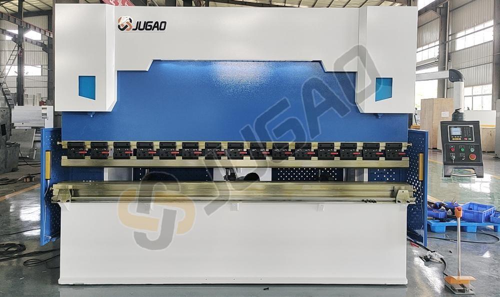
Introduktion till E21-systemet
I modern metallbearbetning spelar pressbromsar en avgörande roll vid böjningsoperationer av plåt. Denna handledning behandlar specifikt maskiner utrustade med E21-styrsystem och erbjuder komplett vägledning för installation, drift och kalibrering. Oavsett om du är en ny operatör eller behöver repetera dina kunskaper hjälper denna manual dig att uppnå optimal maskinprestanda.
Del 1: Hydrauliskt system och elektriska anslutningar
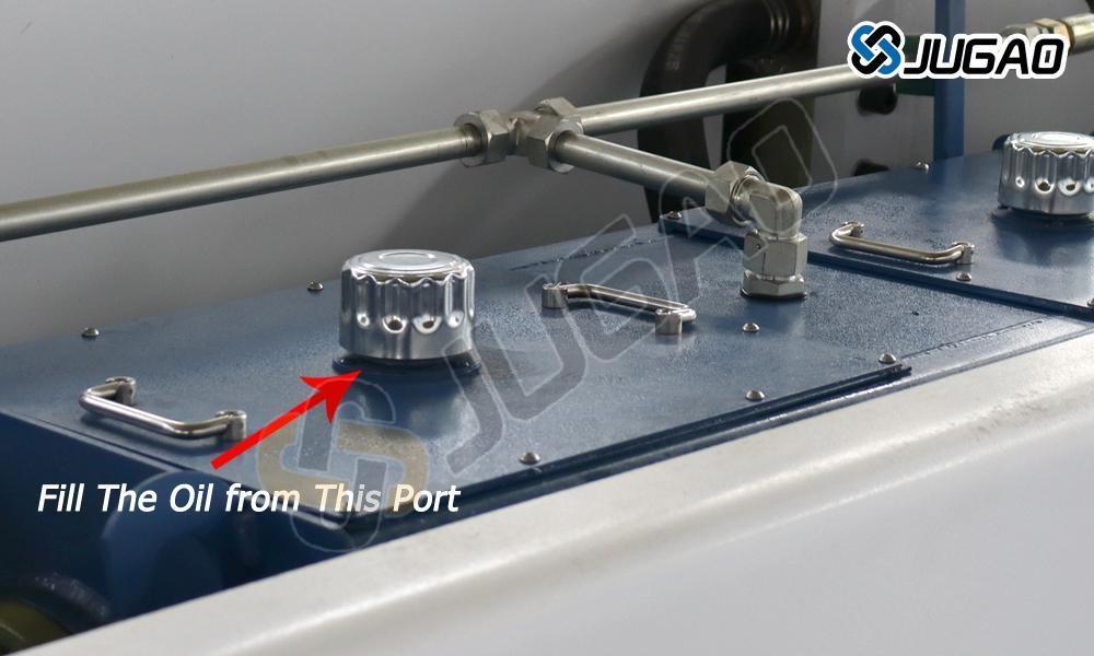
Korrekt fyllning av hydraulolja
För optimal prestanda hos din E21 NC-pressbroms ska hydrauliktanken fyllas med slitagehämmande hydraulolja. Denna specialolja minskar friktion och reducerar slitage på hydrauliska komponenter. Använd den avsedda fyllningsöppningen för oljan och håll nivån inom rekommenderade gränser. Undvik att fylla över och använd inte olja av lägre kvalitet, eftersom detta kan orsaka ineffektivitet i systemet och potentiell skada. Regelbundna kontroller av oljenivå samt tidiga utbyten är avgörande för att upprätthålla topprestanda hos pressbromsen.
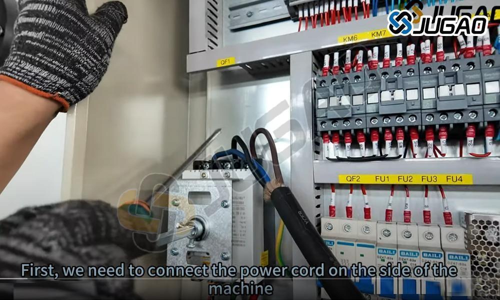
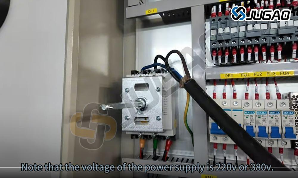
Elkraftanslutning
Innan du startar CNC-pressbänken måste du säkerställa att den är korrekt ansluten till en trefasig elkälla. Detta är avgörande för stabil drift och för att förhindra elektriska fel. Kontrollera att spänningsförsörjningen överensstämmer med maskinens specifikationer. Alla anslutningar ska utföras av en behörig elinstallatör, vilket säkerställer säkra kablar som uppfyller säkerhetsstandarder. Efter anslutning ska jordningen kontrolleras för att förhindra elektriska faror. Aktivera huvudströmbrytaren och kontrollera kontrollpanelen för eventuella felmeddelanden. Om inga problem uppstår är systemet klart för drift. Följ alltid tillverkarens anvisningar för säker och effektiv användning.
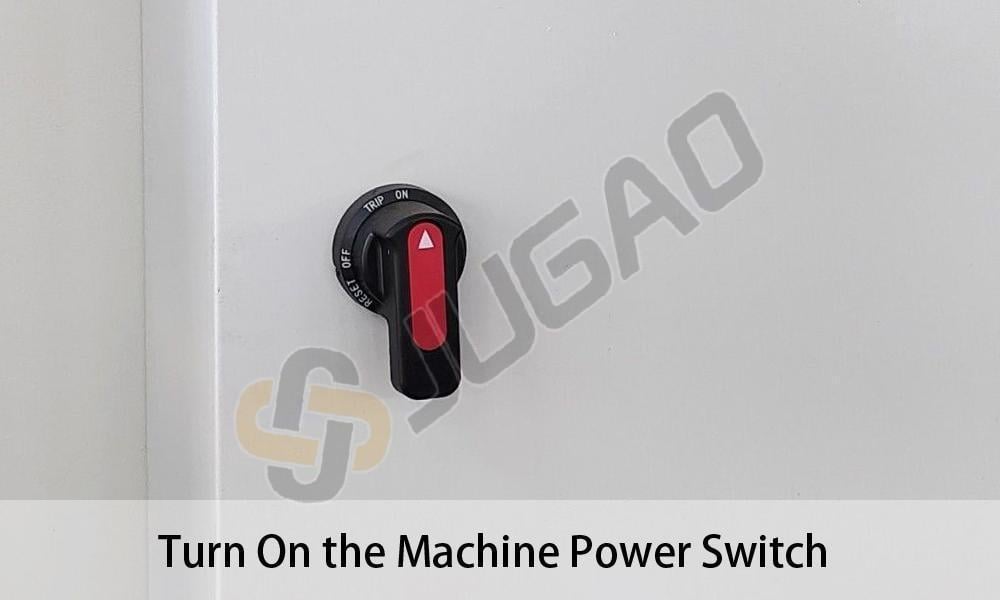
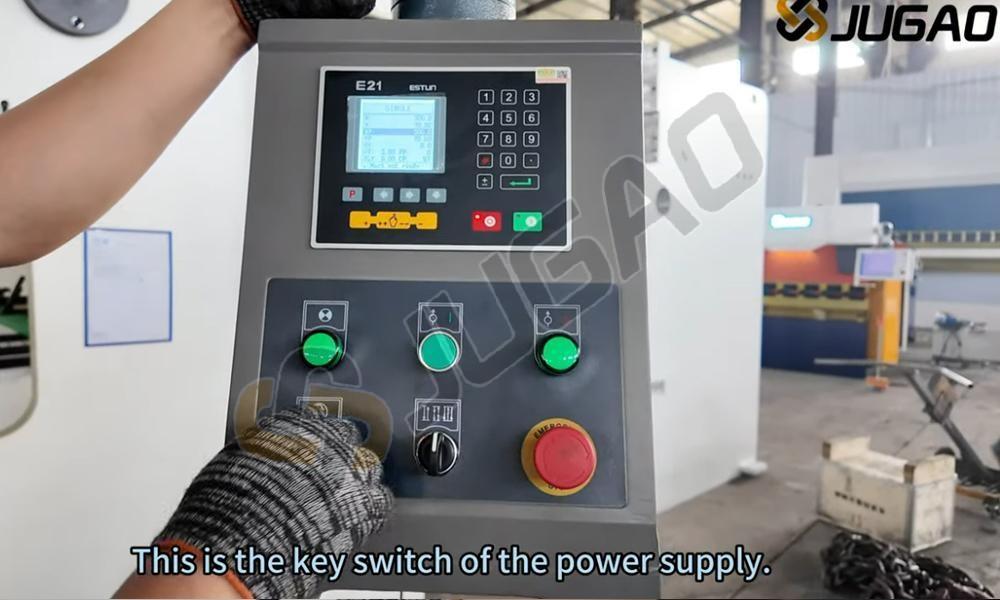
Strömstartsekvens
Innan du använder E21 NC-pressbänken ska du kontrollera att strömanslutningen är stabil och att spänningen är kompatibel. Leta upp huvudströmställaren, som vanligtvis sitter på maskinens sida eller baksida. Vrid om strömställaren till läge "ON" och vänta några sekunder medan systemet startar. Kontrollpanelen ska visa uppstartsinformation som indikerar att systemet är klart. Om felkoder visas ska du konsultera användarhandboken för felsökning. Alltid följ säkerhetsprotokollen innan du påbörjar böjningsoperationer.
Maskinens strömaktivering
Se till att strömförsörjningen är stabil med rätt spänning innan du startar. Leta upp huvudströmställaren på kontrollpanelen eller elskåpet. Vrid omkopplaren till läge "ON" och vänta på systeminitiering. Kontrollera att kontrollerns skärm tänds och visar startgränssnittet. Lyssna efter ovanliga ljud som kan indikera elektriska problem. Om systemet inte startar korrekt, undersök strömkällan och nödstoppknappen. Bär alltid lämplig skyddsutrustning och följ säkerhetsförfarandena under maskinens drift.
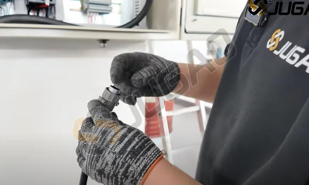
Fotpedsanslutning
För korrekt drift av E21 NC-pressbroms, anslut fotpedalen säkert till maskinen. Leta upp den dedikerade anslutningsporten för pedalen på kontrollpanelen eller maskinbasen. Justera pedelanslutningen med porten och sätt i den ordentligt tills den klickar på plats. Se till att anslutningen är tät för att förhindra oavsiktlig frånkoppling under drift. Testa pedalens respons med lätt tryck. Om maskinen inte svarar, kontrollera anslutningarna och strömförsörjningen. En korrekt ansluten pedal förbättrar både säkerhet och driftkontroll under böjningsprocesser.
Systemström aktivering
Starta E21 NC-gaffeltruckens drift genom att hitta huvudströmbrytaren på kontrollpanelen. Bekräfta stabil elkoppling innan du vänder brytaren till läge "PÅ". Indikatorlampa eller aktiverad skärm bekräftar lyckad start. Tillåt systeminitiering innan du påbörjar drift. Om maskinen inte startar, kontrollera strömförsörjning, nödstoppknapp och säkringar. Följ alltid elektrisk säkerhetsinstruktion vid hantering av komponenter.
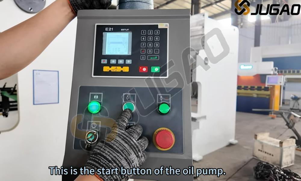
Aktivering av hydraulpump
Innan du startar E21 NC-pressbänken måste du säkerställa att strömanslutningen är korrekt. Leta upp pumpens strömbrytare på kontrollpanelen och aktivera den för att starta hydraulsystemet. En jämn brusighet indikerar normal pumpfunktion. Kontrollera nivån på hydrauloljan och undersök efter läckage eller onormala ljud. Om systemet inte startar korrekt ska du undersöka strömanslutningarna och nödstoppknappen. Korrekt aktivering av pumpen säkerställer stabil trycknivå och smidiga böjningsoperationer, vilket förhindrar bearbetningsfel. Följ alltid säkerhetsprotokollen vid hantering av maskiner.
Nödstoppfrigöring
För att återuppta normal E21 NC-pressbromsoperation, släpp nödstoppet (E-stopp) på fotpedalen. Denna viktiga säkerhetsfunktion stoppar omedelbart maskinens funktioner för att förhindra olyckor. Släpp genom att trycka fast eller vrida moturs (beroende på modell) tills knappen återgår till sin ursprungliga position. Efter släppning, kontrollera kontrollpanelen för att bekräfta systemåterställning. Se till att pedalen är stabil innan du fortsätter med arbetet. Korrekt hantering av E-stopp förbättrar säkerheten och säkerställer obestörda böjningsprocesser.
Aktivering av maskinstart
När du trycker på ENTER-nyckeln startas böjsekvensen för E21 NC-pressbänken. Efter att alla parametrar – inklusive böjvinkel, materialtjocklek och position för backgauge – har verifierats, tryck på ENTER för att bekräfta och köra programmet. Systemet styr släden genom exakt böjning enligt förinställda värden. Se alltid till att arbetsstycket är korrekt placerat och att alla säkerhetsåtgärder är vidtagna innan maskinen aktiveras. Detta avgörande steg möjliggör effektiv och noggrann metallböjning, vilket förbättrar både produktivitet och kvalitet inom plåtbearbetning.
Verifikation av huvudmotorrotation
Innan du kör E21 NC-pressbromsen ska du kontrollera huvudmotorns rotationsriktning för att säkerställa korrekt funktion. Felaktig rotation kan orsaka ineffektiv drift eller skador på systemet. Efter att strömmen har kopplats på ska du iaktta motorns rörelse. Om rotationen är felaktig ska två fasledare bytas ut för att rätta till fasserien. Se till att motorn fungerar smidigt innan du påbörjar maskinens arbetsprocesser. Regelbundna kontroller av rotationsriktning förhindrar onödig slitage och säkerställer konsekvent bötnoggrannhet och längre livslängd på maskinen.
Betydelse av medurs rotation
Vid användning av E21 NC-pressbänkssystemet är korrekt inställning av knopp eller motorrotationens riktning avgörande. Medurs rotation indikerar vanligtvis rätt rörelse, vilket säkerställer exakt positionering och konsekvent böjningsnoggrannhet. Motsols rotation kan signalera felaktiga inställningar, vilket potentiellt kan orsaka fel i böjvinkeln eller feljustering. Kontrollera alltid rotationsriktningen innan du påbörjar bögningsoperationer. Korrekt maskininställning och kalibrering säkerställer effektivitet, förlänger verktygslivet och förbättrar den totala produktionskvaliteten inom metallbearbetning.
Förklaring av motsols rotation
Rotering moturs går i motsatt riktning till klockans visare. I mekaniska system indikerar denna rotation ofta omvänd rörelse eller specifika funktionskrav, såsom lossning av fästelement eller särskild växling. I vikbänkar och industriell maskineri påverkar motor- eller axelrotationsriktningen prestanda, precision och säkerhet. Korrekt rotationsriktning förhindrar mekaniska fel och optimerar effektivitet. Operatörer bör verifiera rotationsriktningen vid installation för att undvika driftproblem. Vid oväntad rotation moturs ska man undersöka motorsladdning och systeminställningar.
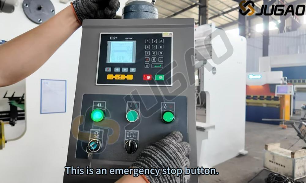
Nödstopp aktiverat
Under E21 NC-pressbromsens drift ska nödstoppknappen omedelbart tryckas in vid funktionsstörning eller säkerhetsrisk. Denna åtgärd avbryter omedelbart maskinens strömförsörjning, vilket förhindrar ytterligare rörelse och säkerställer operatörens säkerhet. Kontrollera alltid att nödstoppknappen är lättåtkomlig innan du påbörjar böjningsoperationer. Regelbundna kontroller av knappen säkerställer korrekt funktion och obegränsad tillgänglighet. Efter aktivering ska felet identifieras och åtgärdas innan drift återupptas. Korrekt användning av denna säkerhetsfunktion minimerar risker och förbättrar arbetsplatsens säkerhet.
Justering av elanslutning
Felaktig koppling i E21 NC-pressbänken kan orsaka rörelseriktningfel eller systemresponsproblem. Om bakstopps- eller krammets rörelse är felaktig ska två ledningsanslutningar bytas ut på motorn eller kontrollpanelen. Denna justering omvänder motorfasordningen och återställer korrekt funktion. Innan ändringar utförs ska systemet kopplas från elen, och kopplingsscheman ska konsulteras för att förhindra elektriska faror. Efter ledningsjustering ska maskinen startas om och rörelsen testas för verifiering. Denna snabba lösning säkerställer effektivitet och förhindrar onödigt stopp.
Del 2: Systeminitiering
E21 NC Pressbänk Igångsättning
Innan du använder E21 NC-pressbänken måste du säkerställa en stabil strömanslutning. Leta upp huvudströmstängaren på elpanelen, vanligtvis placerad på maskinens sida eller baksida. Vrid omkopplaren till läge "ON" och vänta på att systemet startar. Kontrollpanelen ska visa uppstartsinformation som indikerar att systemet är klart. Kontrollera om det finns felmeddelanden eller varningar. Om allt är normalt kan du fortsätta till valet av böjningsparametrar. Följ alltid säkerhetsföreskrifter när du hanterar elektriska komponenter för att förhindra potentiella risker.
Aktivering av styrsystem
Börja E21 NC-gallpressoperationen genom att hitta huvudströmbrytaren på kontrollpanelen. Vrid om brytaren till läge "ON" och observera att indikatorlampan tänds, vilket bekräftar mottagen ström. Se till att spänningsförsörjningen är stabil och korrekt konfigurerad för att förhindra systemfel. Efter påslagning, ge systemet tid att initieras. Kontrollera E21-kontrollerns skärm för att se startskärmen som standard. Åtgärda eventuella varningsmeddelanden innan du fortsätter. Korrekt strömaktivering är grundläggande för säker och effektiv drift.
Hydraulsystemets start
Börja E21 NC-gallpressoperationen genom att starta oljepumpen. Se till att strömförsörjningen är stabil och att maskinen är korrekt ansluten. Tryck på startknappen för oljepumpen på kontrollpanelen för att aktivera hydraulsystemet. En jämn brummande ljudbild indikerar normal pumpdrift. Kontrollera efter ovanliga ljud eller vibrationer. Ge oljan cirkulationstid innan du påbörjar maskinoperationer. Korrekt pumpstart säkerställer stabil trycknivå, smidig böjprestanda och långsiktig maskintillförlitlighet.
Nödstoppets avaktivering
Innan du börjar arbeta med E21 NC-pressbänken måste du korrekt frigöra nödstoppomkopplaren. Denna viktiga säkerhetsfunktion gör det möjligt att omedelbart stoppa maskinen i händelse av olycka. Frigör genom att vrida omkopplaren medurs tills den lossnar, vilket indikerar att systemet återaktiveras. Efter frigöring ska du kontrollera kontrollpanelen för felmeddelanden och nollställa om det behövs. Verifiera maskinens säkerhetsstatus innan du fortsätter med drift. Korrekt hantering av nödstoppomkopplaren säkerställer säkerhet och förhindrar onödiga avbrott.
Fotpeds nödstoppfrigöring
För att återuppta E21 NC-godkännande av brutningsmaskinen, släpp nödstoppet (E-stopp) på fotpedalen. Kontrollera först att E-stoppknappen är aktiverad – om den är aktiv, vrid medurs för att återställa. Se till att fotpedalen är korrekt placerad utan hinder. Testa systemets respons med lätt tryck på pedalen. Om maskinen inte startar, kontrollera säkerhetslås och återställ styrenheten. Korrekt frigöring av E-stopp säkerställer smidig drift och förhindrar produktionsavbrott under processer för böjning av metall.
Startkommando för drift
När ENTER-tangenten trycks ned aktiveras E21 NC-böjpressen och böjprocessen startar. Innan du trycker på ENTER ska alla parametrar verifieras, inklusive böjvinkel, bakåtstoppsposition och tryckinställningar. Efter bekräftelse signalerar tryckning på ENTER att maskinen ska utföra böjsekvensen. Övervaka processen för att säkerställa smidig drift och bibehållen precision. Viktiga säkerhetsåtgärder inkluderar att hålla händerna borta från rörliga delar och använda skyddsutrustning. Korrekt användning av ENTER-funktionen förbättrar effektiviteten, minskar fel och säkerställer konsekvent böjnoggrannhet inom metallbearbetning.
Del 3: Driftslägen
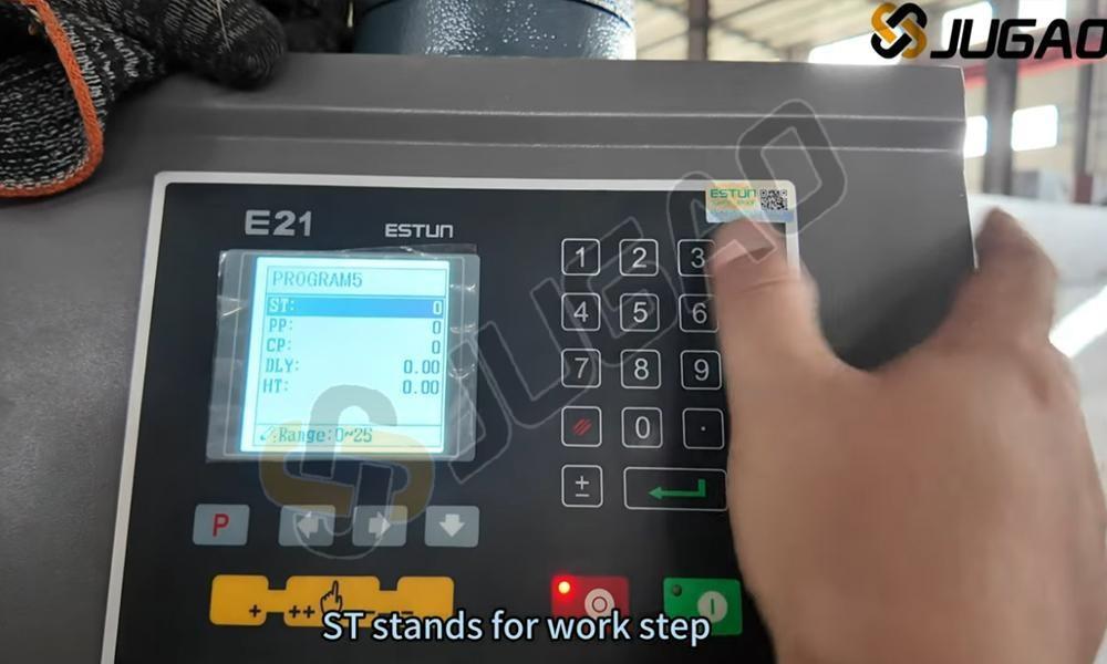
Enkel lägesdrift
Det enskilda läget i E21 NC-pressbänken möjliggör manuell bearbetning av enskilda böjsteg. Detta läge är perfekt för liten serieproduktion och anpassade böjuppgifter, vilket ger flexibilitet och exakt kontroll över varje operation. Användare kan ställa in böjvinklar, positioner för bakåtstopp och slaggränser innan varje steg utförs separat. Systemet säkerställer noggrann prestanda samtidigt som det tillåter justeringar i realtid. Det enskilda läget är särskilt värdefullt för prototypframtagning och specialprojekt, vilket garanterar hög precision utan komplex programmering. Att behärska detta läge ökar effektiviteten och minimerar fel i plåtböjningsoperationer.
Jog-läge Funktionalitet
Jog-läge i E21 NC-pressbromsen ger manuell kontroll av släpkursernas rörelse för exakt positionering. Detta läge underlättar vid verktygsinställning, vinkelmätning och noggrannhetskontroll innan fullt arbete påbörjas. Genom att trycka på jog-knappen rör sig släpkurserna stegvis, vilket ger operatören full kontroll över böjningsdjup och justering. Denna funktion är särskilt användbar för finjustering, minskar fel och förbättrar arbetseffektiviteten. Använd jog-läge med försiktighet för att undvika överjustering. Behärskning av denna funktion ökar maskinens precision och säkerställer konsekventa böjresultat, vilket gör den väsentlig för installation och kalibrering.
Kontinuerligt driftsläge
Kontinuerlig läge i E21 NC-pressbänken möjliggör oavbrutna böjningsoperationer, vilket förbättrar effektiviteten vid massproduktion. När det aktiveras cyklar maskinen automatiskt genom böjsekvenser utan att kräva omstart av operatören mellan varje cykel. Detta läge är idealiskt för högvolym bearbetning av plåt, minskar driftstopp och ökar produktiviteten. Operatörer bör kontrollera korrekt verktygsjustering och materialplacering innan kontinuerligt läge aktiveras, för att säkerställa noggrannhet och konsekvens. Regelbunden övervakning är nödvändig för att förhindra feljustering eller fel. Effektiv användning av kontinuerligt läge möjliggör snabbare produktionscykler och konsekvent böjkvalitet, vilket optimerar den totala driftprestandan.
Del 4: Systemprogrammering och drift
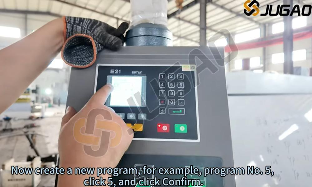
E21 NC Pressbänksprogrammering
E21 NC-pressbroms är utrustad med ett enkelt men kraftfullt programmeringsgränssnitt för effektiv metallböjning. Operatörer kan ställa in böjvinklar, bakåtgångslägen och stegsekvenser via den digitala kontrollpanelen. Systemet stöder flerstegsprogrammering, vilket gör det möjligt att lagra flera böjsteg för komplexa projekt. För optimal prestanda bör korrekt materialinmatning, rätt verktygsval och regelbunden systemkalibrering säkerställas. E21-styrningen erbjuder användarvänlig drift och är därför lämplig för mindre till medelstora metallverkstäder. Genom att behärska E21 NC-programmering kan användare öka produktiviteten och böjningsprecisionen, vilket minskar fel och materialspill.
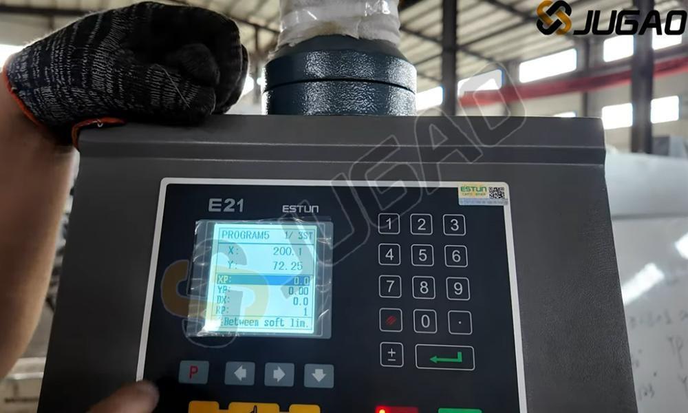
Parameterinställning för böjningsoperationer
För exakta resultat med E21 NC-pressbroms är korrekt justering av YP- och XP-värden avgörande. Ställ in YP-värdet till 93 för exakt ramposition, vilket direkt påverkar böjningsdjup och konsekvens. Justera XP-värdet till 50 för att optimera bakåtstoppläge för exakt materialjustering. Korrekt kalibrering av parametrar förbättrar böjnoggrannheten, minskar materialspill och förbättrar den totala effektiviteten. Regelbunden kontroll och finjustering av dessa inställningar förbättrar maskinens prestanda avsevärt, vilket säkerställer högkvalitativa böjningar med minimala fel i plåtbearbetning.
Korrigering av böjvinkel
För 93-graders böjningar istället för de förväntade 90 graderna krävs justeringar för att förbättra noggrannheten. Detta vanliga problem orsakas av materialåterfjädring, felaktigt val av stans/skärningsverktyg eller otillräckliga tryckinställningar. Korrigeringsmetoder inkluderar ökad tonnage, användning av smalare V-dörröppningar eller tillämpning av överböjningstekniker för att kompensera för återfjädring. Dessutom hjälper verifiering av bakåtstoppläge och kalibrering av vikbänken till att uppnå exakta 90-gradersvinklar. Regelbunden kontroll av materialtjocklek och böjparametrar säkerställer konsekvens och minimerar produktionsfel. Rätt justeringar förbättrar böjnoggrannheten och den totala effektiviteten.
Böj längdjustering
Med nuvarande böjningslängd på 55 mm mot en krävd 50 mm är noggranna justeringar nödvändiga. Kontrollera inställningarna i E21 NC-styrenheten och se till att backgauge-positioneringen är korrekt kalibrerad. Justera böjningsparametrarna i styrsystemet och verifiera att stansen och dies är korrekt justerade för att minimera avvikelser. Vid behov ska materialpositioneringen finjusteras och testböjningar utföras för att bekräfta precisionen. Regelbunden underhåll av backgauge och hydraulsystem säkerställer konsekventa resultat. Korrekt justering säkerställer exakt böjning, minskar materialspill och förbättrar produktionseffektiviteten.
Del 5: Systemkalibrering
Kalibreringsförfarande för Y-axeln
Y-axelkalibrering på E21 NC-böjpress säkerställer exakt böjdjup och konsekvens i metallbearbetning. Korrekt kalibrering justerar stötelementets rörelse enligt programmerade böjparametrar, vilket förhindrar avvikelser och materialspill. För att kalibrera, kom åt E21-kontrollenheten, navigera till Y-axelinställningar och mata in korrekta referensvärden baserat på verktyg och materialtjocklek. Utför testböjningar och mät resultaten för finjustering. Regelbunden kalibrering bibehåller precision och förlänger verktygslivslängden, vilket säkerställer högkvalitativa böjar. Följ alltid tillverkarens riktlinjer för optimal prestanda och för att förhindra feljustering vid böjpressoperationer.
Justering av YP-värde
Att ställa in YP-värdet till 93,2 avgör glidarens djup under böjning. Högre YP-värden möjliggör djupare glidarpenetration, vilket ger mindre böjvinklar. Tvärtom begränsar lägre YP-värden glidarrörelse och skapar större böjvinklar. Korrekt justering säkerställer noggranna och konsekventa böjresultat, minskar materialspill och förbättrar effektiviteten. Operatörer bör finjustera YP-inställningar utifrån materialtjocklek och önskade vinklar för optimal precision. Regelbunden kalibrering av YP-värde är nödvändigt för att upprätthålla högkvalitativa böjar i plåtbearbetning.
Kalibreringsprocess för X-axeln
Riktig kalibrering av X-axeln är avgörande för exakt positionering av backgauge i E21 NC-böjpressen. För att kalibrera, kom åt parameterinställningarna på E21-kontrollenheten och ange den faktiska backgaugepositionen. Använd noggranna mätverktyg för att verifiera avståndet mellan backgauge och böjlinjen. Gör nödvändiga justeringar och spara inställningarna. Regelbunden kalibrering förhindrar dimensionsfel och förbättrar böjningskonsekvensen. Kontrollera alltid igen efter verktygsbyte eller underhåll. En välkalibrerad X-axel förbättrar effektiviteten, minskar omarbete och säkerställer högpresterande metallbearbetning.
Programmeringsläge Åtkomst
När man opererar E21 NC-pressbänken, går man in i programmeringsläge genom att dubbelklicka på tangenten "P". Detta gör det möjligt att effektivt ställa in böjvinklar, bakåtstopplägen och slagparametrar. I programmeringsläge matar operatörer in numeriska värden och bekräftar inställningarna för exakta böjoperationer. Denna funktion förbättrar arbetsflödets effektivitet, minskar installationsstiden och minimerar fel. Kontrollera alltid att inställningarna är korrekta innan du påbörjar böjoperationer för optimala resultat. Att behärska detta steg förenklar användningen av E21 NC-styrenheten och gör metallböjning mer noggrann och effektiv.
Systemlösenordsinmatning
För att komma åt E21 NC-böjningspressens avancerade inställningar, navigera till CONST-sidan på kontrollgränssnittet. När du uppmanas till det, ange lösenordet 1212 för att låsa upp begränsade konfigurationsalternativ. Detta möjliggör justering av systemparametrar, optimering av böjningsprecision och operativa ändringar. Korrekt inmatning av lösenord är avgörande för att förhindra åtkomstproblem. Efter upplåsning ska inställningarna noga granskas och konfigureras enligt kraven för metallböjning. Vid osäkra justeringar, konsultera användarhandboken eller kontakta teknisk support.
Val av lägesläge
På TEACH-sidan säkerställer lämplig X-Tea-val optimala lärandeupplevelser anpassade till specifika behov. Varje X-Tea-alternativ ger omfattande insikter, vilket förenklar förståelsen av centrala begrepp. Oavsett om du söker nybörjarguider eller avancerat tekniskt innehåll erbjuder TEACH-sidan strukturerade val. Navigera bland tillgängliga X-Tea-alternativ, jämför funktioner och välj de som matchar dina lärmål. Med tydliga instruktioner och organiserat innehåll kan du snabbt förstå väsentlig kunskap för effektiv tillämpning i verkligheten.
Inmatning av böjlängd
När du konfigurerar E21 NC-pressbromsen säkerställer inmatning av exakt verklig böjningslängd korrekta resultat. För en erforderlig böjningslängd på 55 mm ska du mata in 55 i kontrollsystemet. Detta säkerställer att bakåtstop och böjningsparametrar stämmer överens med arbetsstyckets mått, vilket förhindrar fel i den slutgiltiga böjningen. Korrekt inmatning minimerar materialslöseri och ökar produktiviteten. Kontrollera alltid inmatade värden innan du startar arbetet för att undvika feljustering. Korrekt inmatning av data i E21-systemet är avgörande för konsekvent böjnoggrannhet och optimal effektivitet i pressbromsen.
Återupptagande av böjprocessen
Under E21 NC-pressbromsens drift kan du snabbt återuppta böjningen genom att dubbelklicka på "P"-knappen på kontrollenheten. Denna funktion är särskilt användbar vid ompositionering eller justering av arbetsstycket innan du fortsätter med böjsekvenserna. Efter att ha dubbelklickat på "P" återgår maskinen till föregående böjposition, vilket möjliggör en smidig och effektiv arbetsflöde. Denna funktion förbättrar driftshastighet och noggrannhet samt minskar tiden mellan böjoperationer. Att behärska denna funktion säkerställer högre produktivitet och precision vid plåtbearbetning. Kontrollera alltid positioneringen innan du fortsätter för att undvika feljustering.
Del 6: Produktionsoperationer
90-graders böjteknik
Den 90-graders böjvinkeln är en standard inom metallbearbetning, vilket säkerställer exakta och konsekventa resultat. Uppnåendet av denna vinkel beror på faktorer som materialtjocklek, val av dies och inställningar på pressbänk. Lämplig V-dies bredd och punschradie är avgörande för att bibehålla noggrannhet. Dessutom säkerställer justering av böjkraft och positionering av bakre stoppupplag upprepbarhet. Operatörer bör ta hänsyn till återfjädringskompensation för att förhindra avvikelser. Användning av CNC- eller NC-styrda pressbänkar säkerställer konsekvens vid flera böjningar, vilket minskar fel och förbättrar effektiviteten. Korrekt kalibrering och val av verktyg är väsentligt för perfekta 90-graders böjningar.
Förståelse av böjlängd
Böjningslängden i E21 NC-pressbromssystemet anger den maximala plåtlängd som kan böjas i enstaka operationer. Detta bestäms av maskinens arbetsbordstorlek och verktygskonfiguration. En korrekt inställning av böjningslängd säkerställer exakta böjresultat, minimerar materialspill och förhindrar överbelastning av verktyg. Användare bör alltid kontrollera maskinspecifikationer, välja lämpliga stansar och diear samt justera bakstoppspositionering för noggranna resultat. Att förstå böjningslängd är avgörande för att optimera produktiviteten och uppnå konsekvent böjnoggrannhet vid plåtbearbetning.
Del 7: Systemavstängning
Hydraulpumpavaktivering
Pumpstoppbrytaren är en viktig komponent i E21 NC-pressbromssystemet, som gör det möjligt för operatörer att säkert stänga av hydraulpumpen under maskinens inaktivitet. När brytaren aktiveras stoppas pumpen omedelbart, vilket förhindrar onödig energiförbrukning och minskar slitage på hydraulsystemet. Stäng alltid av pumpen efter drift för att förlänga maskinens livslängd och säkerställa säkerheten i arbetsplatsen. Innan du startar om bör du kontrollera att pumpen är korrekt inkopplad för att undvika systemfel. Regelbunden underhåll och korrekta avstängningsförfaranden säkerställer optimal prestanda hos pressbromsen.
Nödstoppapplikation
Nödstoppknappen (Emergency Stop) är en avgörande säkerhetsfunktion på E21 NC-pressbänken. När knappen aktiveras stoppas alla maskinoperationer omedelbart, vilket förhindrar potentiella farliga situationer. Operatörer bör använda nödstopp vid plötsliga driftstörningar, oväntad materialrörelse eller säkerhetsrisker. Efter aktivering måste maskinen återställas innan drift återupptas. Regelbundna funktionstester av nödstoppanordningen säkerställer tillförlitlighet. Korrekt användning av denna funktion förbättrar arbetsplatsens säkerhet och skyddar både operatörer och utrustning. Följ alltid säkerhetsanvisningarna när du arbetar med E21 NC-pressbänken.
Korrekt systemavstängning
Innan underhåll eller avstängning av E21 NC-pressbromsen ska strömbrytaren kopplas ur. Leta upp huvudströmbrytaren på kontrollpanelen och vrid den till läge "OFF". Detta säkerställer elektrisk säkerhet och förhindrar oavsiktliga igångsättningar eller driftstörningar. Bekräfta alltid att strömmen är helt frånkopplad innan justeringar eller inspektioner utförs. Korrekta avstängningsförfaranden förlänger maskinens livslängd och säkerställer säkerheten för operatören. Dessutom minskar frånkoppling av strömmen vid längre inaktivitet energiförbrukningen och skyddar elektroniska komponenter mot eventuella överspänningar.
Slutsats
Denna användarhandbok för E21-systemet ger en omfattande förståelse av NC-pressbänkens funktion med E21-systemet. Genom att behärska väsentliga steg – inklusive fyllning av hydraulolja, elektriska anslutningar, systemkalibrering och böjningsoperationer – uppnås maximal effektivitet och precision hos pressbänken. Korrekt installation och kalibrering är avgörande för konsekventa, exakta böjningar och optimerad maskinprestanda i produktionsmiljöer. Denna kunskap säkerställer inte bara högkvalitativa resultat utan förlänger även utrustningens livslängd samt minskar driftstopp orsakade av operativa fel.
Vid problem eller behov av förtydliganden erbjuder vårt experthjälpstjänstteam omedelbar assistans. Vi är dedikerade till att optimera din NC-pressbänks prestanda och erbjuder omfattande eftersäljningstjänster för smidig drift.
För ytterligare information om E21-systemet eller intresse för vår sorts pressbänkar och industriella maskiner, besök vår webbplats. Vi tillhandahåller omfattande resurser inklusive produktmanualer, videokurser och detaljerade specifikationer för att maximera din utrustningsanvändning. För frågor kontakta oss direkt via informationen på vår webbplats.

