





How to Rectify Laser Beam Offset for Fiber Laser Equipment
Even a tiny positional shift within the optical route will give rise to laser beam offset on fiber laser cutting devices. This defect will bring about diminished cutting precision, fluctuating section finish, and inflated service expenses. Whenever operators observe erratic machining output or unexpected power attenuation, beam offset problems constitute one of the most likely root causes. This article offers systematic guidance for spotting and remedying such optical deviation faults, enabling your JUGAO fiber laser unit to resume high‑precision, steady production rapidly. Thorough troubleshooting and timely modification play a vital role in sustaining long‑run processing performance and equipment dependability.
Insights Into Laser Beam Offset on Fiber Laser Machinery
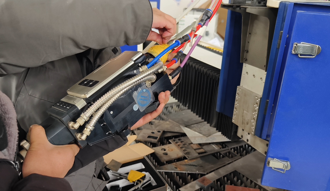
Primary Sources Triggering Laser Beam Offset
Laser beam offset emerges once the optical transmission route suffers disturbance. Multiple factors can induce this fault: sustained mechanical oscillation, improper component mounting, thermal deformation during equipment operation, as well as physical impact generated in transit or on‑site relocation.
Why Accurate Beam Centering Is Indispensable
For fiber laser hardware, laser radiation must travel perfectly through each lens element, reflective fittings and cutting‑head assembly. Even negligible misalignment will produce these adverse outcomes:
• Deteriorated dimensional accuracy of finished parts
• Non‑uniform kerf width across cutting contours
• Surface scorch traces or partial penetration failure
• Power loss when laser energy reaches the nozzle outlet
Step‑by‑Step Operational Guide for Rectifying Beam Offset
Step 1: Power Cut‑Off and Safety Precaution Implementation
Prior to commencing any modification work, fully shut down the whole machine and disconnect power supply. Laser processing devices carry high‑energy risks, so safety protocols should always be prioritized.
Step 2: Full Inspection of Optical Assembly Parts
Examine the complete set of optical accessories, covering protective windows, collimation lenses and focusing lenses. Surface dust, component scratches or wrong assembly positions will directly destabilize the beam transmission path.
Step 3: Carry Out Optical Path Centering Verification
Adopt centering test paper or low‑energy test pulse mode to confirm whether laser spots stay centered as they pass each optical unit. Spot drift detected in this procedure confirms beam offset inside the optical route.
Step 4: Fine‑Tune Reflective Elements and Optical Module Positions
If your device is fitted with tunable reflectors or optical modules, perform tiny incremental adjustments strictly complying with JUGAO official technical specifications. Minor repeated tweaks are critical to restore ideal beam transmission status.
Step 5: Validate Centering Status of the Laser Cutting Head
The cutting head assembly needs to maintain strict vertical posture and beam centering. Confirm the nozzle keeps coaxial alignment with outgoing laser light; eliminate tilt and mechanical positional shift to secure consistent and reliable cutting performance.
Step 6: Execute Trial Cutting and Complete Parameter Calibration
Once adjustment operations finish, run trial machining on scrap workpieces of identical material grade. Assess edge surface quality, kerf uniformity and material piercing depth, to verify that beam centering has been fully recovered.
Preventive Measures Against Recurring Beam Offset Faults
Formulate Cyclic Maintenance Checklists
Weekly visual inspection for optical components is strongly recommended. Apply designated lens cleaning wipes to clear surface contaminants. This practice helps steer clear of offset faults induced by dirty optics, and preserves stable beam performance in long‑term mass production.
Minimize Unwanted Mechanical Oscillation
Mechanical vibration ranks among top contributors to gradual beam drift. Deploy solid installation foundations and retighten structural fasteners periodically, to retain long‑term machining precision.
Standardize Machine Transportation & Operating Procedures
When carrying out equipment relocation or field installation, handle JUGAO fiber laser systems with great care. Prevent collision shocks which would trigger optical misalignment, and keep optical assemblies and beam pathways well‑calibrated for reliable cutting results.
Frequently Asked Questions
What warning signals appear at the early phase of laser beam offset?
Typical early‑stage symptoms include inconsistent piercing depth, coarse cutting section, and decreased processing efficiency, even under correct power parameter configurations.
Is it feasible to correct beam offset without specialized tooling?
Simple preliminary checks and minor fine‑tuning can be accomplished using common centering test targets. Nevertheless, high‑accuracy calibration work ought to adopt tooling suggested in JUGAO operation manuals.
What is the advised cycle for beam centering inspection?
Carry out beam centering inspection every one to two months. Immediate verification is also required whenever you spot obvious degradation of cutting quality.
Closing Remarks
Rectifying laser beam offset is critical for preserving cutting accuracy, production efficiency and service lifespan of fiber laser equipment. By adopting structured inspection workflows, careful fine‑tuning and scheduled preventive maintenance, you can achieve stable equipment operation and reduce unplanned production downtime.
Should you demand further technical consultation or customized operation guidance for your JUGAO fiber laser model, please get in touch with our technical support group. Our specialists stand ready to help you maintain optimal production conditions.

