





How do you set the welding path for a robotic laser welding machine? Can it perform precise welding on complex workpieces?
Thanks to their high level of automation, superior welding precision, and consistent production capacity, robotic laser welding machines have become the go-to welding equipment in sectors such as hardware, new energy, automotive parts, and precision sheet metal fabrication. However, many manufacturers and operators new to automated welding often face two primary challenges:
First, they struggle with setting the welding path, finding the robot control system daunting or confusing to navigate.
Second, they worry that complex, irregularly shaped, or multi-bend, narrow-gap workpieces cannot be welded with sufficient precision—leading to issues like off-target welds, missed spots, or uneven weld seams.
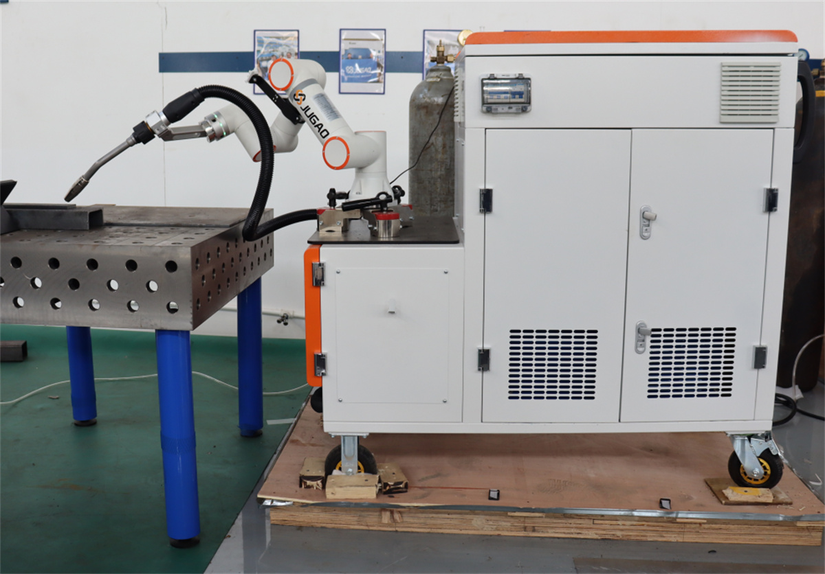
In reality, setting a welding path for a robotic laser system is not an overly complex technical task. By mastering standardized procedures and applying the appropriate programming and debugging methods, users can easily define paths and achieve high-precision welding—even on complex workpieces—thereby overcoming the inherent accuracy limitations of manual welding.
This article provides a detailed walkthrough of the complete process for setting robotic laser welding paths, along with solutions for achieving precise welds on complex parts, helping you overcome practical hurdles and boost operational efficiency.
I. Preliminary Preparation: Laying the Foundation for Precise Welding
Proper preparation is the key to accurate path setting and error-free welding. Skipping this step often leads to off-target welds or path misalignment. Whether you are working with simple or complex parts, the following preparatory steps must be completed:
1. Positioning of Workpieces and Fixtures
Robotic welding is a standardized, automated process that requires highly accurate workpiece positioning. First, the workpiece must be securely fastened within a dedicated fixture, ensuring it is level, stable, and free from any movement or shifting, with the welding area positioned well within the robot’s operational reach. Simultaneously, the fixture itself must be calibrated to ensure that, for every batch of parts loaded, the weld points and seam locations remain perfectly consistent—preventing any path deviations caused by workpiece displacement.
2. Equipment and Laser Welding Torch Calibration
After powering on the system, perform a "home" (zero-position) reset for the robot to ensure an accurate reference for the robotic arm's movement. Next, calibrate the orientation and focal length of the laser welding torch. Adjust the torch's height and angle based on the workpiece's thickness and material to ensure the laser spot is precisely centered on the weld seam. Additionally, inspect the torch’s protective lens and the wire-feeding mechanism (if filler wire is required) to ensure they are free of debris and obstructions, preventing any negative impact on welding precision.
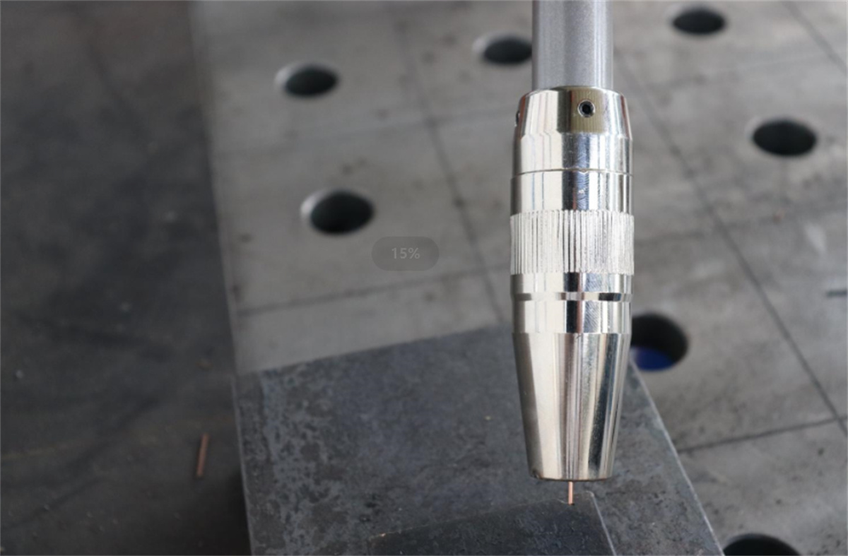
3. Preset Basic Welding Parameters
Pre-configure core parameters—such as laser power, welding speed, wire-feed speed, and gas flow rate—based on the workpiece material (e.g., stainless steel, aluminum alloy, copper) and thickness. Establishing these foundational welding parameters in advance eliminates the need for repeated adjustments during the subsequent path-programming phase, allowing you to focus solely on calibrating the path coordinates and improving overall setup efficiency.
II. Robotic Laser Welding Path Programming: Two Main Approaches
Robotic laser welding paths are typically programmed using either "teach programming" or "offline programming." The former is ideal for simple workpieces and beginners, as it requires no prior experience; the latter is better suited for complex workpieces or high-volume production involving frequent product changeovers, offering higher precision and greater efficiency. You can choose the method that best fits your specific workpiece type and operational requirements.
Method 1: Teach Programming (Most Common; Recommended for Beginners)
Teach programming is the most widely used method for defining welding paths on the shop floor. It involves using a manual teach pendant to guide the robot and record the welding path point by point. This approach is simple and intuitive—perfect for defining paths for standard geometries like straight lines, arcs, or basic irregular shapes—and can be completed directly on-site without the need for specialized software.
Complete Steps for Teach Programming
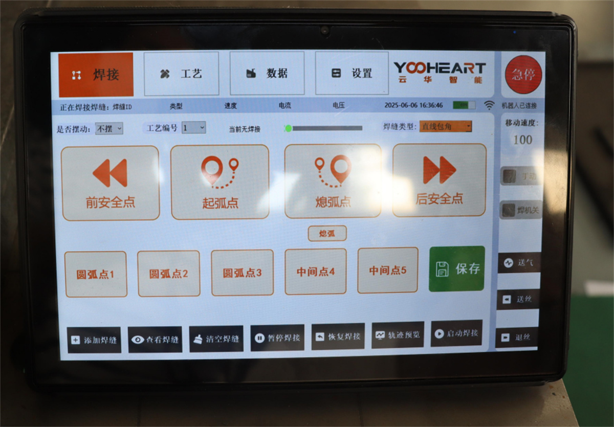
1. Switch to Teach Mode: Set the robot control cabinet to "teach mode" and unlock the robotic arm. Use the teach pendant to maneuver the robot, ensuring that control permissions are active and that the operation is performed safely.
2. Point Teaching and Recording: Operate the robotic arm to move the welding torch, aligning it sequentially with key locations such as the start point, inflection points, end points, and arc transition points of the weld seam. Upon reaching each precise location, press the "Record" button on the teach pendant; the system will automatically save the coordinates. For simple, straight weld seams, only the start and end points need to be recorded, whereas complex, multi-bend seams require recording each key inflection point.
3. Trajectory Path Generation: Once all key points have been recorded, select the desired trajectory type (linear, circular, or continuous) on the teach pendant. The system will automatically connect the points to generate a complete welding path.
4. Trajectory Speed Adjustment: Fine-tune the welding speed for different segments of the path—for instance, reduce the speed at narrow gaps or corners, and increase it along long, straight sections—to ensure a uniform weld bead and prevent deviation.
5. Dry-Run Simulation: Disable the laser output and execute a "dry run" (simulated movement) of the robot along the programmed path. Verify that the path aligns accurately with the weld seam, check for any misalignments, and ensure there is no risk of collision with the workpiece or fixtures. Proceed to actual test welding only after confirming everything is correct.
Method 2: Offline Programming (High Precision; Preferred for Complex Workpieces)
Offline programming utilizes specialized robotic software to perform trajectory modeling, path planning, and simulation-based debugging on a computer. This approach does not require the robot to be taken out of production, making it ideal for complex, irregularly shaped workpieces, multi-dimensional or winding weld seams, and high-precision components. It offers significantly higher trajectory accuracy than manual teaching and eliminates the risk of collisions during on-site programming.
Complete Offline Setup Steps
1. 3D Model Import: Import the 3D CAD model of the workpiece into the offline programming software. This recreates the actual dimensions, weld seam locations, and geometry of the workpiece, establishing a virtual working environment.
2. Virtual Trajectory Planning: Within the software, manually map out the welding path based on the orientation of the weld seams. Configure corners, arcs, and spacing to accommodate the specific geometries of complex workpieces, such as irregular seams, narrow gaps, or deep grooves.
3. Parameter and Orientation Setting: Configure the welding torch orientation, laser parameters, and travel speed within the software. Simulate the entire welding process to optimize the motion path and avoid potential collisions or interference points.
4. Program Export and Transfer: Once the path planning is complete, generate an executable program compatible with the robot. Transfer this program to the robot’s control cabinet via a data cable or USB flash drive to load it into the system.
5. On-Site Fine-Tuning and Calibration: After loading the program, perform a "dry run" (simulation). Make minor adjustments to the path points to account for any slight discrepancies between the actual workpiece and the virtual model, ensuring the path aligns perfectly with the actual weld seam.
III. Can Complex Workpieces Be Welded with Precision? Core Solutions
For complex workpieces—such as those with irregular curved surfaces, multiple bends, narrow gaps, deep cavities, hard-to-reach corners, or ultra-thin precision components—robotic laser welding can achieve high-precision, error-free results, provided that path optimization and the appropriate supporting configurations are implemented. This effectively eliminates issues like weld misalignment, missed welds, and inconsistent weld beads. The core solutions are as follows:
1. Integration of a Vision-Based Positioning System (The Key to Precision)
This is the essential configuration for the precise welding of complex workpieces. By incorporating a laser-based or CCD-based vision system, the robot can automatically identify the location of the weld seam and track its path. Even if there are minor positioning deviations in the workpiece, the vision system can adjust the robot’s path in real-time, enabling dynamic tracking. This eliminates the need for repetitive manual adjustments and significantly enhances welding accuracy for complex, irregular parts or scenarios involving frequent product changeovers—keeping errors within 0.05 mm.
2. Optimization of Motion Paths and Welding Orientation
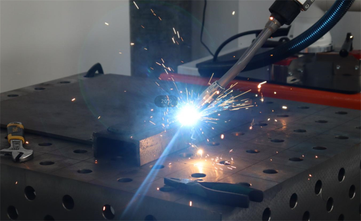
For workpieces featuring multiple bends, corners, or narrow gaps, avoid abrupt, rigid changes in the motion path; instead, use arc transitions rather than sharp, right-angled turns to prevent the laser spot from shifting. Adjust the tilt angle of the welding torch based on the workpiece structure to accommodate deep cavities or hard-to-reach areas, ensuring the laser remains perpendicular to or properly aligned with the weld seam throughout the process. Additionally, reduce the welding speed at corners to allow for uniform heat distribution, thereby preventing weld misalignment or excessive heat input (over-welding).
3. Utilize High-Precision Robots and Fixtures
For welding complex workpieces, prioritize the use of six-axis industrial robots with high-precision servo control; these offer smoother operation and minimal path deviation. Pair them with customized, high-precision fixtures—featuring dedicated positioning slots tailored to the specific geometry of the workpiece—to ensure the part remains completely immobile and perfectly aligned, guaranteeing path accuracy from the very start.
4. Segmented Teaching and Fine-Tuning
For highly complex or multi-segment weld seams, employ a segmented approach to teaching and debugging. Break down the complex path into smaller, simpler segments, calibrating points and fine-tuning parameters for each section individually. Once completed, these segments are integrated into a full, cohesive path. This method reduces the overall complexity of the debugging process and ensures that every segment of the weld is executed with precision.
IV. Summary of Practical Path Configuration
When configuring paths for robotic laser welding, use "teaching" (on-robot programming) for simple workpieces—it is efficient, convenient, and easy to learn. For complex workpieces, combine offline programming with vision-based positioning to achieve maximum precision and high adaptability. By ensuring accurate initial positioning and calibration, following standardized programming workflows, and optimizing path parameters for specific requirements, you can achieve precise welding on everything from standard straight-seam parts to complex components with irregular shapes, bends, or deep cavities—fully leveraging the precision and efficiency advantages of robotic laser welding.
For beginners, it is best to start by practicing "teaching" on simple workpieces. Once you have mastered the techniques for recording points and debugging paths, you can progress to offline programming for more complex parts. This step-by-step approach will allow you to confidently manage path configuration and overcome challenges related to welding precision.

