


Jak naprawić uszkodzony czujnik w maszynie do gięcia rur?
Czujniki są „końcówkami nerwowymi" maszyny do gięcia rur, odpowiedzialnymi za monitorowanie kluczowych parametrów, takich jak kąt gięcia, położenie rdzenia, stan zacisku oraz skok podawania. W przypadku awarii czujnika urządzenie może wykazywać odchylenie kąta, niestandardowe zachowanie lub wyłączenie z alarmem. Opanowanie metod diagnostyki i naprawy uszkodzeń czujników jest ważną umiejętnością zapewniającą prawidłową pracę urządzenia.
Typowe rodzaje czujników oraz objawy ich uszkodzeń
Do typowych czujników stosowanych w maszynach do gięcia rur należą:
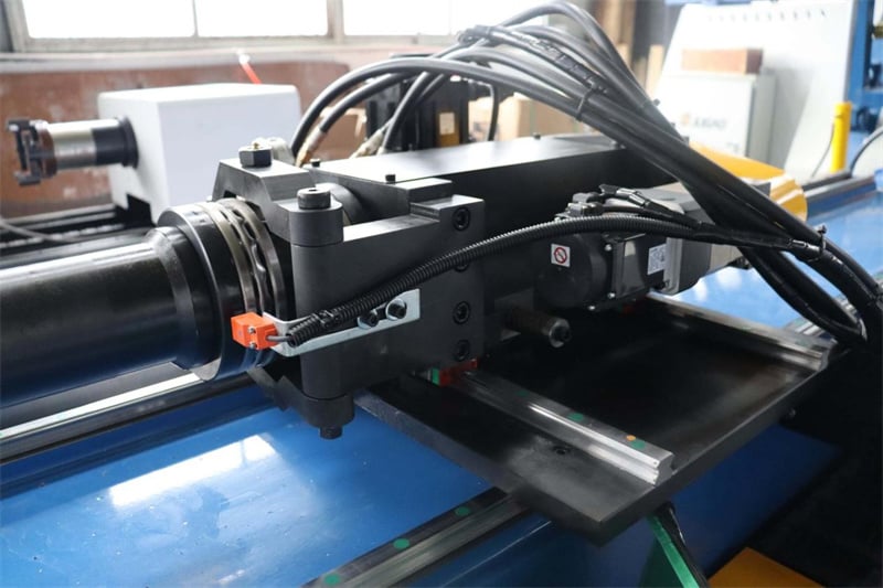
Czujnik kąta / enkoder: Monitoruje kąt obrotu ramienia gięcia. Objawy uszkodzenia: duże odchylenie kąta gięcia, nietypowa sprężystość powrotu, niestabilne wyświetlanie kąta lub brak sygnału.
Włącznik zbliżeniowy: wykrywa sygnały położenia, takie jak zaawansowanie/odwracanie rdzenia, położenie zacisku oraz punkt początkowy podawania. Objawy usterki: brak reakcji, fałszywe wyzwalanie, niestabilny sygnał.
Czujnik przemieszczenia: mierzy skok cylindra lub długość podawania. Objawy usterki: niedokładne wymiary, fluktuacje sygnału oraz niestabilne wartości wyświetlane na ekranie.
Kroki diagnostyki i naprawy
Krok 1: Wyłączenie zasilania i potwierdzenie bezpieczeństwa
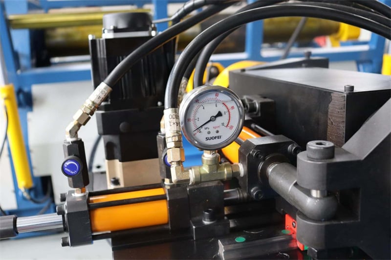
Przed przystąpieniem do jakiejkolwiek konserwacji czujników należy zawsze wyłączyć główne zasilanie urządzenia oraz zrzucić ciśnienie z układu hydraulicznego, aby zapobiec przypadkowemu uruchomieniu i obrażeniom.
Krok 2: Inspekcja wizualna
Sprawdź czujnik pod kątem pęknięć, odkształceń lub zanieczyszczeń olejem. Sprawdź, czy zaciski nie są luźne lub utlenione, a także czy powłoki kabli nie są zużyte lub uszkodzone. Sprawdź powierzchnię czujnika pod kątem pyłu lub drobnych odłamków metalu – jest to częsta przyczyna awarii włącznika zbliżeniowego.
Krok 3: Testowanie parametrów elektrycznych
Użyj multimetru do przeprowadzenia trzech kluczowych testów: sprawdź, czy napięcie zasilania mieści się w zakresie nominalnym (np. DC12–24 V lub AC90–250 V); sprawdź, czy napięcie sygnału wyjściowego jest prawidłowe; sprawdź, czy prąd obciążenia przekracza wartość nominalną. W przypadku enkoderów użyj oscyloskopu, aby ocenić stabilność kształtu fali sygnału wyjściowego oraz czy amplituda spełnia wymagania.
Krok 4: Rozwiązywanie problemów związanych ze sygnałem i zakłóceniami
Upewnij się, że pozycja montażu czujnika jest stabilna oraz że odległość pomiarowa między czujnikiem a obiektem mierzonym jest odpowiednia. Sprawdź, czy w pobliżu znajdują się silne źródła zakłóceń elektromagnetycznych (np. przemienniki częstotliwości, silne silniki elektryczne). W razie konieczności dodaj ekranowanie do przewodu sygnałowego i uziem go z jednej strony.
Krok 5: Kalibracja i sprawdzenie parametrów
Jeśli odchylenie kątowe jest duże, należy przekalibrować punkt zerowy czujnika. Sprawdź, czy ustawienia parametrów czujnika w systemie sterowania są poprawne, np. zakres pomiaru i protokół komunikacji. W przypadku enkoderów sprawdź również, czy klucz połączeniowy nie wysunął się z rowka klucza oraz czy elementy fotoelektryczne nie są zabrudzone.
Krok 6: Zamiana uszkodzonego czujnika
Jeśli powyższe kroki nie rozwiążą problemu, oznacza to, że uszkodzone są wewnętrzne komponenty czujnika, a zatem należy wymienić czujnik tego samego modelu. Przy wymianie upewnij się, że zasilanie jest wyłączone, prawidłowo podłącz przewody, po wymianie przeprowadź ponowną kalibrację parametrów oraz wykonaj próbne uruchomienie w celu weryfikacji.
Zalecenia dotyczące konserwacji zapobiegawczej
Regularnie czyść powierzchnię czujnika odpowiedzialną za wykrywanie, aby zapobiec obniżeniu czułości detekcji przez olej i kurz.
Kalibruj czujnik co sześć miesięcy, aby zapewnić dokładność pomiarów.
Utrzymuj zapas czujników; zaleca się posiadanie części zamiennych dla czujników w krytycznych lokalizacjach.
Wybieraj czujniki o wyższych stopniach ochrony (np. IP67 lub wyższy) do zastosowań w trudnych warunkach środowiskowych.
Zwracaj uwagę na zakres temperatur roboczych czujnika, aby uniknąć przekroczenia wartości nominalnej, co może prowadzić do pogorszenia jego parametrów eksploatacyjnych.
Choć czujniki są niewielkie, to bezpośrednio wpływają na dokładność gięcia rur oraz bezpieczeństwo sprzętu. Opanowanie standaryzowanych procedur diagnostycznych i naprawczych pozwala szybko zlokalizować usterki i skrócić czas przestoju.

