


Mastering ESA S640 Graphic Bending Sequence: Expert Tips and Step-by-Step Guide
In the fast-paced metalworking industry, precision and operational efficiency are the cornerstones of high-quality production. The ESA S640 stands out as a powerful tool for bending operations, with its graphic bending sequence function being a key feature that elevates accuracy and workflow smoothness. Whether you’re a seasoned operator looking to refine your skills or a beginner just getting to grips with the device’s graphic programming capabilities, this comprehensive guide will walk you through every essential step—from setting up a graphic program to executing automatic and manual bending sequence calculations. By mastering these techniques, you’ll be able to optimize your bending processes and achieve superior production results consistently.
Setting Up a Graphic Program in ESA S640
Initiating a graphic program on the ESA S640 is the first step to gaining precise control over all your bending operations, laying the foundation for accurate and repeatable results.
Initial Setup of Graphic Parameters
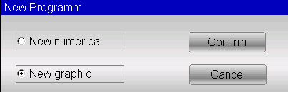
Before creating a new graphic program, it’s critical to input all key parameters accurately. Start by accessing the Editor page, select [New program], and then click [New graphic] to open the general data entry interface. Follow these detailed steps for parameter configuration:
1. Sheet Width and Thickness: Locate the corresponding input fields on the interface, enter the exact width and thickness of the metal sheet to be bent, and confirm each value by pressing [Ok]. This step ensures the press brake is calibrated to accommodate the material, aligning with the ESA S640’s operational specifications.
2. Material Resistance: Tap the material resistance input field to enter the relevant data and confirm with [Ok]. This information is pivotal for the ESA S640’s graphic bending sequence system, as it uses the data to auto-calculate optimal operational settings and boost bending precision.
3. Tool Selection:
○ Die and Punch Selection: Scroll through the toolbar to find the required die from the list and add it to the program by pressing [Insert] (note: the die must be pre-drawn). If multiple V-die options are available, select the appropriate one and set the Die Orientation—0 for the standard position and 1 for a 180° rotation.
○ Punch Setup: Select the pre-drawn punch from the toolbar list and adjust the Punch Orientation according to the specific bending requirements of your project.
Navigating the Drawing Window
After completing the general data entry, you’ll be directed to the drawing window, where you can make precise, project-specific adjustments to your bending design.
Drawing Window Layout
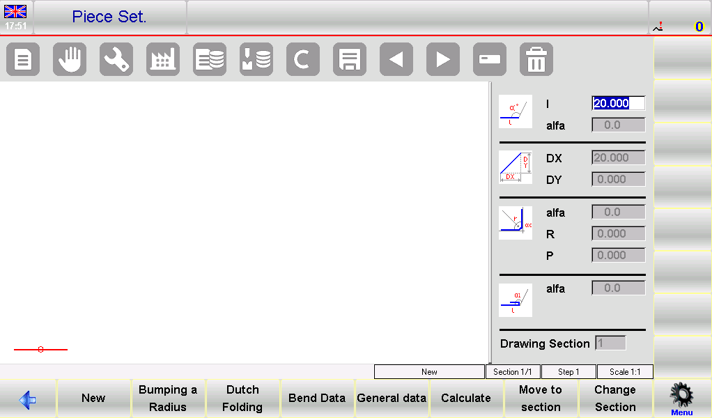
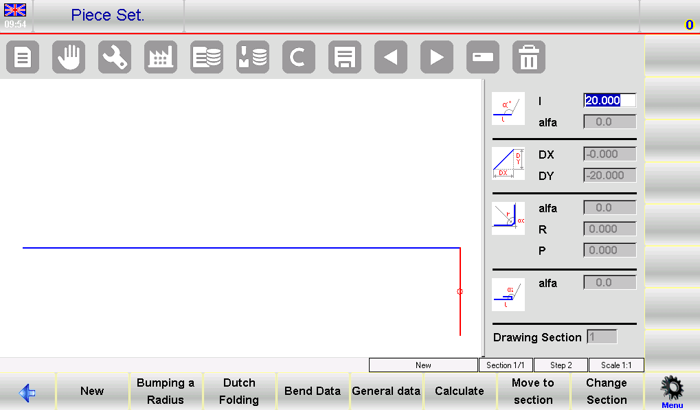
The left side of the screen features the main drawing workspace, while the right side is divided into four dedicated panels for different drawing data types: polar drawing data, Cartesian drawing data (seldom used in daily operations), radius bends data, and Dutch folding bends (hemming) data.
Segment and Angle Adjustments
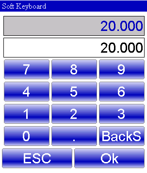
• When you first enter the drawing window, the initial segment appears in red with a default length of 20.0 mm. Tap the “l” field to bring up the Soft Keyboard, which you can use to modify the segment length to match your design requirements.
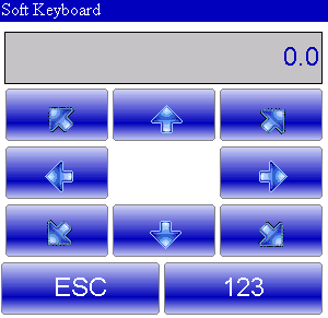
• After setting the segment length, the system automatically focuses on the “alfa” field in the polar drawing data panel. Here, you can use the Soft Keyboard to adjust the bending angle: predefined angles (45°, 90°, 135°, 180°, -135°, -90°, -45°) are available for quick selection, and custom angles can also be input for highly specific bending needs.
• Once the angle is set, the system reverts to the length input for the next segment. Use the Soft Keyboard to set the length, and repeat this process to build out your entire bending design step by step.
Utilizing Bend Sequencing and 3D Viewer
The ESA S640’s bend sequencing and 3D Viewer features provide a holistic view of the bending process, enabling thorough inspection and precise adjustments before actual production:
1. Accessing Bend Sequence: Navigate to the AUTOMATIC graphic page, open the menu, and select 0>> Bending sequence. You can then review and verify each bend in the sequence to ensure alignment with your design.
2. 3D Visualization: Select 3>> 3D Viewer from the menu to access a 3D perspective of the bending design and sequence. This immersive view allows for detailed checks of every component and bend, making it easy to spot and correct potential issues early on.
Automatic Bending Sequence Calculation
The ESA S640’s automatic bending sequence calculation function streamlines the planning process, minimizing manual input and significantly boosting operational efficiency. Mastering this feature lets you leverage the device’s advanced capabilities to achieve optimal bending results with ease.
Generating Automatic Sequences
Once your entire bending design is complete, navigate to the PIECE SETTING page and press the [Calculate] button to initiate the automatic sequence calculation. This action opens a calculation window that displays a full simulation of the workpiece, along with critical equipment components including the press brake, punch, die, and stops.
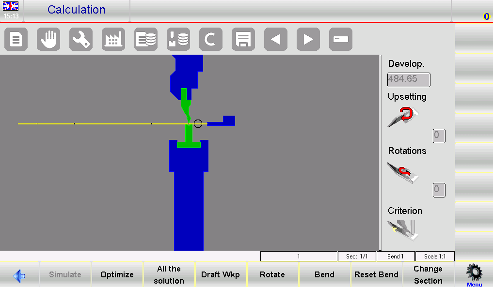
• Simulation Setup: The right-hand window in the simulation interface shows key data such as upsetting parameters, rotation details, and the selected calculation criterion.
• Solution Search: By default, the system prioritizes safety and operational ease by searching for bending sequences that keep the majority of the metal sheet in the operator’s hand throughout the process. For more complex projects, you can adjust the calculation criterion to explore all possible bending sequences.
• Optimization: Press the [Optimize] button for an automatic search; the ESA S640’s numerical control system will then identify the optimal bending sequence and make real-time adjustments to ensure safe material handling during production.
Simulation for Optimized Results
After the optimal sequence is determined, simulating the entire bending process is essential to ensure smooth, error-free operations:
1. Initiate Visualization: Press the [Simulate] key to view the flat workpiece, prepped for the first bending operation. The simulation clearly displays each step of the bending process in sequence.
2. Real-Time Support Position Adjustment: Use the [Rest/Support] function to set the workpiece’s support positions, ensuring the machine’s stops only activate when it is safe to do so. If no collision points are detected in the simulation, proceed to the next step.
3. Full Sequence Simulation: Press the [Continue] function key to run through the entire bending sequence step by step. Meticulously check each bend for precision and safety; if any issues are identified, press the [Stop] key to halt the simulation and make adjustments.
Manual Bending Sequence Calculation
For complex bending scenarios that require customized control, the ESA S640’s manual bending sequence calculation function allows operators to fine-tune every step of the process, ensuring precise results for unique project requirements.
Customizing Bending Sequences Manually
Start by pressing [Calculate] from the drawing page—this opens a simulation window showing the workpiece and all press brake components. From here, you can manually define the bending sequence:
• Press the [Bend] key at the desired locations on the workpiece to add bends; the same key can also be used to straighten any pre-set bends that need adjustment.
• Use the [Rotate] key to reposition the metal sheet, fine-tuning its alignment to ensure perfect setup for each bend.
Once all desired bends and their positions are defined, press [Optimise]. The ESA S640’s numerical control system will then lock in and execute the custom sequence you’ve created.
Handling Potential Issues
Manual bending sequence setup may encounter challenges, particularly if the designed workpiece has inherent feasibility issues. Here’s how to address common problems:
1. Collision Detection: If a collision with any machine component is detected, the system will signal this with a color change on the interface. Manually inspect the collision points, then adjust the bending sequence or force specific bends to find a safe, feasible alternative.
2. Resolving Non-Damaging Collisions: For minor, non-damaging collisions, you can manually adjust the sequence step by step to force the completion of the full bending process until a workable solution is achieved.
3. Post-Adjustment Simulation: Always simulate the modified sequence after making adjustments. This final check verifies that the changes resolve issues and ensure the sequence is accurate and operationally safe.
By using the ESA S640’s manual adjustment features, operators can effectively tackle even the most complex bending tasks, maintaining precision and safety at every step.
Frequently Asked Questions (FAQ)
Can the ESA S640 automatically calculate the bending sequence for any material?
Yes. The ESA S640 is equipped with advanced algorithms that can auto-calculate the optimal bending sequence for a wide range of metal materials. Simply input the material type and sheet thickness into the system, and it will generate the most efficient sequence to minimize production errors and speed up the manufacturing process.
What should I do if I encounter errors in the ESA S640 Graphic Bending Sequence calculations?
If calculation errors occur, start by thoroughly reviewing all input data for inaccuracies—ensure material specifications, sheet dimensions, and tool settings are all entered correctly. If the error persists, refer to the troubleshooting section in the official ESA S640 manual or contact the technical support team for professional assistance. Additionally, regularly updating the system’s software is highly recommended to maintain peak operational performance and prevent software-related errors.
Conclusion
Mastering the ESA S640’s graphic bending sequence function hinges on a thorough understanding of its graphic programming features and proficient use of both automatic and manual bending sequence calculation tools. By following the step-by-step guidelines outlined in this guide and familiarizing yourself with the device’s core capabilities, you can drastically improve the efficiency and precision of your metalworking bending operations.
If you have any questions about optimizing the ESA S640 for your specific production needs, or require further personalized guidance, don’t hesitate to reach out to our professional team for expert advice. You can also explore our other technical documentation to discover more tips and insights for maximizing the performance of your ESA S640 and other JUGAO equipment.

