


Panduan Langkah demi Langkah untuk Pengaturan Punch ESA S640
Jika Anda mencari panduan lengkap tentang penyetelan pukulan (punches) untuk mesin bending ESA S640, panduan ini akan memenuhi kebutuhan Anda. Kami akan menjelaskan setiap langkah proses penyetelan pukulan ESA S640 secara rinci, sehingga operasi Anda berjalan lancar dan presisi tinggi. Baik Anda seorang profesional metalurgi berpengalaman maupun baru memulai penggunaan ESA S640, panduan langkah demi langkah ini akan menghilangkan keraguan Anda serta membekali Anda dengan keterampilan yang diperlukan untuk menyelesaikan penyetelan pukulan secara efisien—sehingga pada akhirnya mengoptimalkan alur kerja fabrikasi logam Anda.
Manajemen Daftar Pukulan
Langkah pertama dalam pengaturan pons S640 ESA adalah mengakses dan mengelola daftar pons secara efektif, yang menjadi fondasi bagi pengoperasian alat yang terorganisasi dan efisien. Di bawah ini terdapat penjelasan rinci mengenai cara mengakses daftar tersebut serta mengelola alat pons Anda.
Mengakses Daftar Pons
1. Alihkan Tampilan: Tekan tombol saklar khusus untuk beralih antara daftar pons dan daftar die. Antarmuka mungkin secara bawaan menampilkan daftar die, sehingga tekan tombol tersebut sekali lagi untuk menampilkan daftar pons.
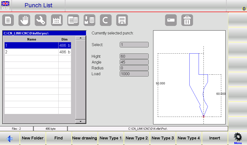
2. Pahami Tata Letak Antarmuka: Setelah daftar pons ditampilkan, antarmuka dibagi menjadi tiga bagian utama:
○ Panel kiri menampilkan katalog lengkap semua pons yang tersedia.
○ Kotak tengah menampilkan seluruh data teknis yang terkait dengan pons yang sedang dipilih.
○ Panel kanan memberikan pratinjau visual dari pons yang disorot dalam daftar.
Pengelolaan Pons yang Efisien
Kuasai penggunaan tombol fungsi sistem untuk menavigasi dan mengelola daftar pekerjaan yang belum selesai (punch list) dengan mudah, serta manfaatkan sepenuhnya fitur pratinjau, penyuntingan, dan pencadangan data guna menciptakan alur kerja yang lebih efisien.
Menavigasi dengan Tombol Fungsi
Gunakan tombol fungsi bawaan untuk menjalankan operasi inti pada daftar pekerjaan yang belum selesai (punch list):
• [Folder Baru]: Buat folder khusus untuk mengkategorikan dan mengatur daftar pekerjaan yang belum selesai (punches) berdasarkan proyek atau operasi yang berbeda.
• [Cari]: Cari dan temukan secara cepat daftar pekerjaan yang belum selesai (punch) tertentu dari seluruh daftar, sehingga tidak perlu menggulir layar secara manual.
• [Gambar Baru]: Rancang daftar pekerjaan yang belum selesai (punch) secara khusus dari awal guna memenuhi kebutuhan fabrikasi yang unik.
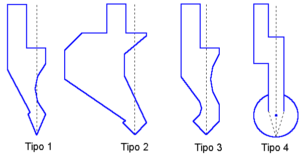
• [Tipe Baru]: Pilih dari tipe daftar pekerjaan yang belum selesai (punch types) yang telah dikonfigurasi sebelumnya (Tipe 1, 2, 3, 4) untuk mempercepat proses penyiapan pada aplikasi standar.
• [Sisipkan]: Tambahkan daftar pekerjaan yang belum selesai (punch) yang dipilih ke dalam program kerja aktif Anda atau tetapkan ke operasi pembengkokan tertentu.
Alat Pratinjau dan Modifikasi
• Aktifkan Pratinjau Alat: Fungsi pratinjau alat diaktifkan secara bawaan untuk membantu Anda mengidentifikasi pukulan secara visual dengan cepat; fungsi ini dapat diaktifkan atau dinonaktifkan sesuai kebutuhan. Untuk menyesuaikan pengaturan ini, buka menu sistem dan pilih opsi 4>> Pratinjau.
• Salin Pukulan: Pilih pukulan target, buka menu, lalu pilih 0>> Salin. Masukkan nama unik untuk pukulan yang disalin dan konfirmasi tindakan untuk menyimpannya.
• Ubah Nama Pukulan: Sorot pukulan yang ingin diubah namanya, akses menu, lalu pilih 1>> Ubah Nama. Masukkan nama baru dan konfirmasi untuk menerapkan perubahan.
Menghapus dan Mencadangkan Pukulan
• Hapus Satu Pukulan: Pilih pukulan yang akan dihapus, konfirmasi pilihan Anda pada jendela pop-up, lalu tekan [Ok] untuk menghapusnya dari daftar.
• Cadangan & Penghapusan melalui USB:
○ Simpan ke USB: Masukkan perangkat USB ke port ESA S640, buka menu, lalu pilih 2>> Simpan Alat untuk mencadangkan semua pukulan dan die ke perangkat eksternal.
○ Hapus Semua Alat: Untuk mengosongkan seluruh katalog pons dan die internal, pilih 3>> Hapus Alat dari menu dan konfirmasi dengan [Ya].
• Kelola Alat yang Disimpan di USB: Masukkan flash drive USB yang berisi data pons dan die yang telah disimpan sebelumnya ke dalam sistem. Anda dapat mengakses dan mengelola alat-alat eksternal ini menggunakan operasi yang sama seperti daftar alat internal.
• Transfer ke Disk NC Internal: Untuk menyimpan alat yang tersimpan di USB ke disk NC internal ESA S640, pilih opsi 2>> Simpan Alat dari menu.
Pengelolaan daftar pons yang tepat menyederhanakan alur kerja pengaturan ESA S640 Anda, menjamin ketepatan dalam tugas pengerjaan logam, meningkatkan produktivitas keseluruhan, serta secara signifikan memangkas waktu penyiapan alat.
Cara Membuat Pons Baru di ESA S640
Membuat pons baru merupakan inti dari proses pengaturan ESA S640, dan dapat dilakukan dengan cara merancang pons khusus dari awal atau memodifikasi jenis pons bawaan agar sesuai dengan kebutuhan Anda. Ikuti petunjuk langkah demi langkah di bawah ini untuk menyelesaikan proses tersebut secara akurat.
Langkah 1: Mulai Pembuatan Pons Baru
1. Buka Perpustakaan Alat: Tekan tombol perpustakaan alat yang ditentukan untuk menampilkan daftar poin pengecekan (punch list) pada antarmuka.
2. Beralih ke Bagian Punch: Jika daftar die ditampilkan secara bawaan, tekan kembali tombol perpustakaan alat untuk beralih ke daftar punch.
3. Pilih Metode Konfigurasi Punch: Pilih cara pilihan Anda untuk membuat punch—baik merancang punch sepenuhnya khusus dari awal, maupun menggunakan salah satu dari empat jenis punch prasetel dengan dimensi bawaan tetap (jenis prasetel ini dapat disesuaikan agar sesuai dengan kebutuhan operasional spesifik Anda).
> Catatan Penting: Gambar punch yang akurat sangat penting bagi pemeriksaan antisimetris (anti-collision) benda kerja oleh sistem, dan dimensi punch yang presisi merupakan dasar untuk menghitung kedalaman pembengkokan. Jika merancang punch khusus dari awal terasa sulit, pilihlah salah satu jenis prasetel lalu sesuaikan parameter-parameter-nya agar mendekati bentuk sebenarnya dari punch menggunakan bidang data yang telah ditentukan sistem.
> Catatan Penting: Gambar punch yang akurat sangat penting bagi pemeriksaan antisimetris (anti-collision) benda kerja oleh sistem, dan dimensi punch yang presisi merupakan dasar untuk menghitung kedalaman pembengkokan. Jika merancang punch khusus dari awal terasa sulit, pilihlah salah satu jenis prasetel lalu sesuaikan parameter-parameter-nya agar mendekati bentuk sebenarnya dari punch menggunakan bidang data yang telah ditentukan sistem.
4. Pilih Tombol yang Sesuai:
○ Tekan [Gambar Baru] untuk merancang punch sepenuhnya khusus.
○ Tekan [Tipe Baru 1]/[Tipe Baru 2]/[Tipe Baru 3] untuk menggunakan masing-masing pons standar yang telah diatur sebelumnya.
○ Tekan [Tipe Baru 4] untuk mengakses pons bulat yang telah diatur sebelumnya.
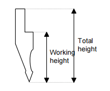
5. Masukkan Spesifikasi Pons: Setelah memilih jenis pons, jendela masukan parameter akan muncul. Masukkan data dimensi utama, seperti tinggi total dan tinggi kerja pons, dengan memastikan semua nilai sesuai dengan kebutuhan fabrikasi Anda.
6. Masuk ke Halaman Gambar: Setelah dimensi dasar dimasukkan, tekan [Ok] untuk mengakses halaman gambar pons. Tata letak halaman akan bervariasi tergantung pada jenis pons yang dipilih. Finalisasi desain pons di sini guna memastikan kesesuaiannya dengan pemeriksaan antisenggolan sistem dan perhitungan kedalaman pembengkokan—keduanya sangat penting bagi keselamatan operasional dan akurasi pemesinan.
Mengikuti langkah-langkah ini secara cermat memastikan bahwa pengaturan pons baru Anda akurat dan disesuaikan khusus dengan operasi metalurgi Anda.
Langkah 2: Gambarkan Geometri Pons
Setelah memasukkan parameter pukulan dasar, langkah berikutnya adalah menggambar geometri pukulan yang tepat menggunakan alat gambar terintegrasi ESA S640. Langkah ini menghasilkan representasi digital yang akurat dari pukulan dan mencegah kesalahan permesinan akibat ketidaksesuaian geometri alat. Fungsi gambar diakses melalui modul gambar khusus sistem, dengan rincian tambahan tersedia dalam panduan pengguna resmi ESA S640.
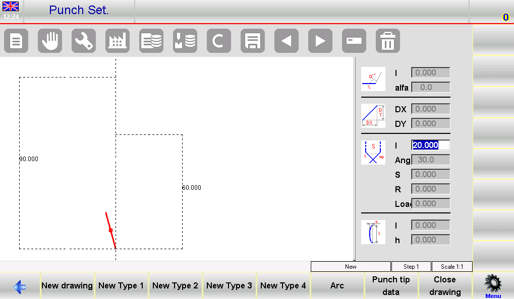
Antarmuka gambar terdiri atas area kerja gambar di sisi kiri dan empat panel entri data di sisi kanan, yang masing-masing digunakan untuk memasukkan koordinat polar, koordinat Kartesius, titik-titik simpul, serta parameter penggambaran busur.
Aturan Menggambar Utama & Entri Titik Simpul
Patuhi konvensi berikut untuk memastikan keakuratan gambar pukulan Anda:
1. Gambar Berlawanan Arah Jarum Jam: Selalu gambar geometri pukulan dalam arah berlawanan arah jarum jam, dan ingatlah bahwa back-gauge mesin terletak di sisi kanan pukulan.
2. Mendefinisikan Ujung Punch (Langkah Kritis): Ujung punch merupakan bagian paling penting dari gambar. Mulailah dengan memasukkan panjang ujung "lp", lalu lanjutkan langkah-langkah berikut:
○ Masukkan dan konfirmasi sudut ujung serta dimensi chamfer (jika diperlukan).
○ Masukkan jari-jari ujung (pada kolom data R) dan tekan [Ok].
○ Masukkan beban punch (ton maksimum per meter) dan konfirmasi nilainya. Urutan ini akan menggambar ujung punch, dan sistem akan menerapkan panjang bawaan untuk bagian punch lainnya guna pengeditan lebih lanjut.
Petunjuk Menggambar Secara Detail
Dengan menggunakan punch standar sebagai contoh, ikuti langkah-langkah berikut saat bekerja di kolom data "lp":
• Masukkan Data Ujung Secara Berurutan: Masukkan nilai panjang dan sudut ujung satu per satu pada kolom yang ditentukan.
• Gunakan Fungsi Busur untuk Kurva: Tekan tombol [Busur] untuk membuat bagian melengkung halus pada punch; masukkan nilai panjang dan kedalaman yang sesuai untuk busur guna menghasilkan bentuk tersebut.
• Menyesuaikan Pengukuran Secara Presisi: Gunakan alat penyesuaian grafis sistem dengan toleransi ±1° (sudut) dan ±1 mm (panjang) untuk menyempurnakan bagian pons, sehingga gambar digital selaras secara maksimal dengan pons fisik.
Perbaiki dan Simpan Gambar
• Lakukan Koreksi: Jika Anda memasukkan data yang salah, navigasikan ke kolom data terkait untuk mengedit dan memperbaiki nilai tersebut.
• Simpan Desain: Setelah gambar selesai dibuat, simpan ke memori internal sistem. Beri nama pons menggunakan kombinasi huruf dan angka (untuk memudahkan identifikasi), lalu tekan [Ok] guna mengonfirmasi penyimpanan.
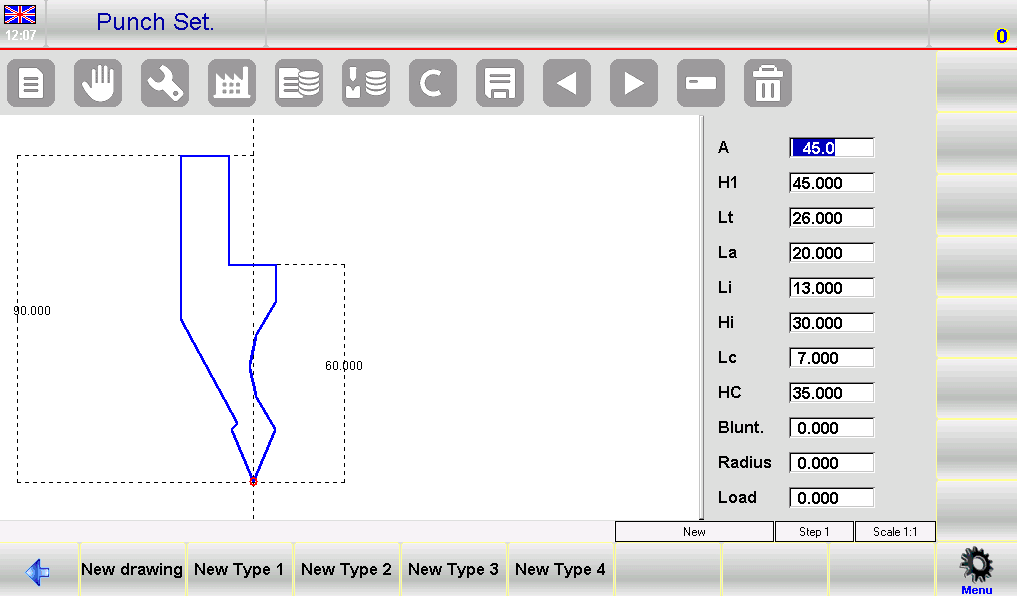
Langkah 3: Bekerja dengan Pons Pra-Setel
Antarmuka pons pra-setel menampilkan geometri pons yang telah digambar sebelumnya, disertai satu set lengkap kolom data yang dapat diedit guna mendefinisikan bentuk dan dimensi pons. Mengubah nilai apa pun dalam kolom-kolom ini dan menekan [Ok] akan secara otomatis menggambar ulang geometri pons sesuai parameter terbaru, sehingga memudahkan penyesuaian setelan baku sesuai kebutuhan Anda.
Simpan Pons Pra-Setel yang Telah Disesuaikan
Setelah menyesuaikan parameter pukulan pra-atur sesuai kebutuhan Anda, simpan desain yang telah disesuaikan untuk digunakan kembali dalam operasi mendatang:
1. Tekan tombol simpan sistem untuk menyimpan pukulan yang telah dimodifikasi ke dalam memori internal ESA S640.
2. Beri nama pukulan dengan label alfanumerik (kami merekomendasikan menggunakan kode katalog resmi pukulan tersebut agar mudah dirujuk).
3. Klik [Ok] untuk mengonfirmasi penyimpanan. Langkah ini memastikan pengaturan khusus Anda tersimpan secara aman dan dapat diakses dengan cepat untuk proses produksi berikutnya.
Finalisasi Pengaturan Pukulan
Setelah semua pukulan dikonfigurasi, digambar, dan disimpan, lakukan pemeriksaan sistem menyeluruh untuk memverifikasi keakuratan semua entri pukulan, parameter, serta gambarannya. Langkah verifikasi akhir ini meminimalkan risiko kesalahan operasional dan menjamin tingkat presisi tertinggi dalam semua tugas pembengkokan press brake.
Dengan mengikuti langkah-langkah terperinci ini untuk penyetelan pons dan die ESA S640, Anda akan memanfaatkan seluruh kemampuan sistem dan secara signifikan meningkatkan efisiensi produksi Anda. Penyetelan pons yang akurat tidak hanya penting untuk pekerjaan logam yang presisi, tetapi juga memperpanjang masa pakai mesin press brake ESA S640 serta perlengkapannya.
Pertanyaan yang Sering Diajukan (FAQ)
Berapa frekuensi yang direkomendasikan untuk memeriksa dan memperbarui penyetelan pons ESA S640?
Kami merekomendasikan agar penyetelan pons ESA S640 diperiksa dan diperbarui setiap 300 hingga 500 jam operasional. Pemeriksaan perawatan berkala harus mencakup verifikasi integritas fisik alat pons, kalibrasi ulang parameter pons dalam sistem, serta pembersihan alat dan komponen mesin terkait guna memastikan kinerja optimal.
Apakah ESA S640 mendukung desain pons khusus selama proses penyetelan?
Ya, sistem ESA S640 sepenuhnya mendukung pembuatan desain pons (punch) khusus selama proses pengaturan. Gunakan fitur [Gambar Baru] pada sistem untuk merancang, menggambar, dan menyimpan konfigurasi pons yang sepenuhnya disesuaikan guna memenuhi kebutuhan unik proyek metalurgi spesifik Anda.
Langkah-langkah apa yang harus saya lakukan jika terjadi ketidaksejajaran pons dalam pengaturan ESA S640?
Jika Anda mengalami masalah ketidaksejajaran pons, pertama-tama tinjau prosedur penyelarasan resmi yang tercantum dalam panduan pengguna ESA S640. Pastikan pons fisik terpasang dengan benar pada mesin dan konfigurasi digitalnya dalam perangkat lunak akurat. Manfaatkan fungsi pratinjau sistem untuk memverifikasi secara visual kesejajaran pons di ruang kerja digital sebelum memulai operasi pemesinan apa pun.
Kesimpulan
Secara ringkas, proses penyiapan pons (punch) ESA S640 melibatkan serangkaian langkah kunci yang terstruktur, yang esensial untuk mencapai kinerja optimal dan presisi tinggi dalam operasi pengerjaan logam. Dengan mengakses dan mengelola daftar pons secara efisien, memanfaatkan jenis pons pra-set untuk penyiapan cepat, merancang pons khusus guna memenuhi kebutuhan unik, serta melakukan perawatan dan pemeriksaan rutin, Anda dapat meningkatkan fungsi mesin bending ESA S640 secara signifikan serta memperpanjang masa pakai operasionalnya.
Untuk dukungan teknis lebih lanjut atau guna mengatasi pertanyaan apa pun yang Anda miliki mengenai penyiapan pons ESA S640, kami merekomendasikan Anda menghubungi JUGAO. Selain itu, jelajahi seluruh rangkaian dokumentasi teknis kami guna memperoleh wawasan dan panduan tambahan dalam memaksimalkan produktivitas serta kinerja peralatan ESA S640 Anda.

