


Hogyan értelmezze a hajlítógépek CNC riasztási kódjait?
Tartalomjegyzék
• Mi azok a présfék CNC riasztási kódok?
• Hogyan olvashatók le a présfék CNC riasztási kódok a Delem vagy az ESA vezérlőkön
○ 1. lépés: Rögzítse pontosan a riasztási üzenetet és a kód számát
○ 2. lépés: Hozzáférés a CNC riasztási előzményekhez
○ 3. lépés: Sorolja be a megfelelő rendszermodult
• Gyakori présfék CNC riasztási kódok és azok gyökérokaik
○ Y-tengely követési hiba riasztás
○ Alacsony hidraulikus nyomás riasztás
○ Hátsó mérőszeg elmozdulása (X-tengely riasztás)
• Lépésről lépésre történő hibaelhárítási protokoll a présfék CNC-riasztási kódjaihoz
○ 1. lépés: A gép üzemeltetésének biztonságos leállítása
○ 2. lépés: Külső és egyszerű kiváltó tényezők ellenőrzése
○ 3. lépés: Az összes elektromos csatlakozási pont vizsgálata
○ 4. lépés: A hidraulikus rendszer stabilitásának megerősítése
○ 5. lépés: A CNC-paraméterek alapos átvizsgálata
• Hatékony intézkedések a gyakori présfék CNC-riasztási kódok megelőzésére
○ Rendszeres megelőző karbantartás bevezetése
○ Az elektromos szekrények tisztaságának és szellőzésének fenntartása
○ A mozdonyvezetők alapvető riasztási logika megértésének oktatása
• Gyakran ismételt kérdések (GYIK)
○ Mi a azonnali teendő, ha megjelennek a sajtófék CNC-riasztási kódjai?
○ Lehetőség van-e a sajtófék CNC-riasztási kódjainak visszaállítására az alapvető probléma megoldása nélkül?
○ Különböznek-e a sajtófék CNC-riasztási kódjai a Delem és az ESA rendszerek között?
○ Milyen stratégiák csökkenthetik a CNC-riasztások gyakoriságát?
• Következtetés
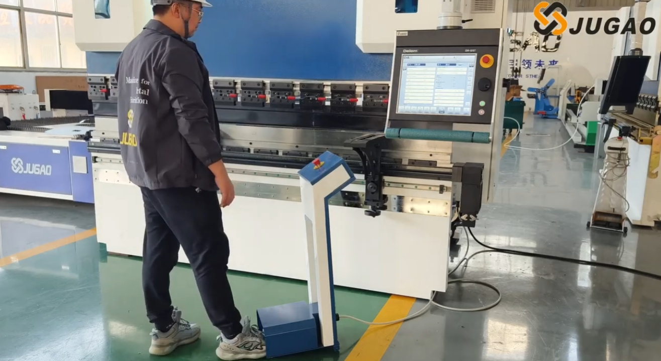
A megmunkálóközpontos (CNC) fékprés riasztási kódjai gyakran váratlanul jelennek meg, hirtelen leállítva a gyártósorokat, és a műszaki személyzetet azonnali beavatkozás nélkül hagyva. Számos elkerülhető gyártási késésre voltam tanúja, amelyek kizárólag a riasztási üzenetek megfelelő értelmezésének hiányából fakadtak. Ha nehézséget okoz számára, hogy értelmezze ezeket a kódokat, akkor ez a részletes útmutató világos iránymutatást nyújt számára. Lépésről lépésre bemutatja, hogyan értelmezze a kódokat, hogyan állapítsa meg, hogy a hiba az elektromos, hidraulikus vagy mechanikus rendszerben jelentkezik-e, és hogyan reagáljon biztonságosan és hatékonyan a problémára. Amint megérti a CNC-riasztási rendszer belső logikáját, a hibaelhárítás módszeresebb feladattá válik, és sokkal kevésbé stresszes – így egykoriban bonyolult folyamatból (JUGAO) hatékony, átlátható folyamat lesz.
Mi az a megmunkálóközpontos (CNC) fékprés riasztási kódja?
A megmunkáló gép CNC-riasztási kódjai az automatizált hibajelzések, amelyeket a gép vezérlőegysége (pl. Delem, ESA vagy Cybelec rendszerek) generál és jelenít meg. Alapvető céljuk a megmunkáló gép, annak szerszámei és a helyszínen dolgozó személyzet védelme a lehetséges károk vagy sérülések ellen.
Gyakorlati tapasztalatok alapján ezeket a riasztási kódokat három fő típusba sorolhatjuk:
• Elektromos rendszer riasztásai
• Hidraulikus nyomás riasztásai
• Tengely- vagy hátsó mérőberendezés pozícionálási riasztásai
Minden kód nem véletlenszerű számérték; egy meghatározott biztonsági védelmi logikát tükröz. Ennek a logikának a megértése az alapja a hatékony hibaelhárításnak.
Hogyan olvassuk el a megmunkáló gép CNC-riasztási kódjait Delem- vagy ESA-vezérlőkön
Bár a különböző CNC-rendszerek eltérő riasztási megjelenítési formátummal rendelkeznek, a kódok értelmezésének alapvető folyamata lényegében azonos.
1. lépés: Jegyezzük fel pontosan a riasztási üzenetet és a kód számát
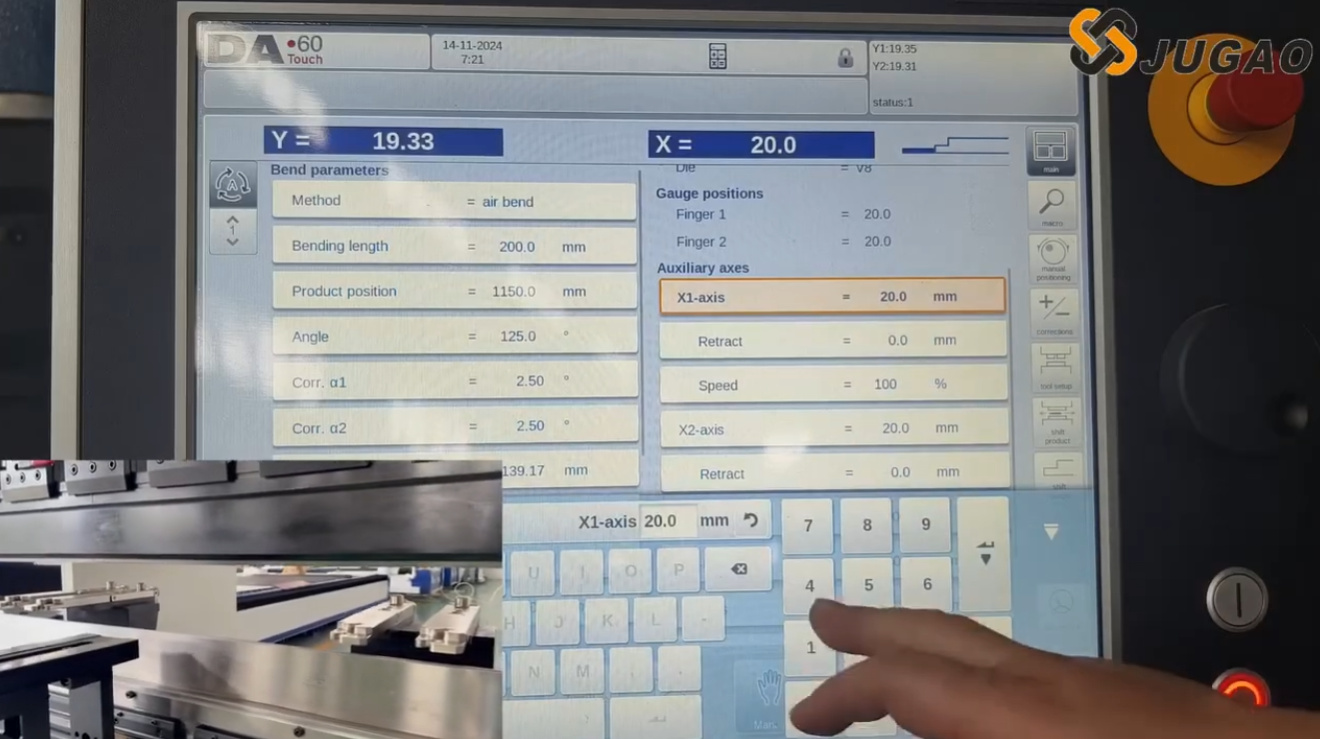
Az első, mindig ajánlott lépés a teljes riasztási üzenet pontos, írásos rögzítése, beleértve annak specifikus számjegyes kódját is. Ilyen üzenetek például:
• „Y1 követési hiba”
• „A hidraulikus nyomás túlságosan alacsony”
• „Hátsó mérőszeg X-tengely pozíciós eltérése”
Soha ne bízzon ebben az információban a memóriájára – még apró különbségek is a kódszámokban teljesen eltérő hibákat jelezhetnek.
2. lépés: A CNC-riasztási előzmények elérése
A legtöbb modern CNC-nyomófékező rendszer részletes naplót vezet minden riasztási eseményről. Lépjen be a rendszer diagnosztikai felületére, és tekintse át a következő kulcsfontosságú adatokat:
• A riasztás pontos időpontja
• Annak ismétlődése (volt-e már korábban ugyanilyen riasztás)
• Annak egybeesése egy adott gépművelettel
Ez az információ döntő fontosságú annak megállapításához, hogy a probléma esetleges hiba vagy tartós, rendszeres hibajelenség.
3. lépés: A megfelelő rendszermodul besorolása
A nyomófék CNC riasztási kódjainak gép funkcionális moduljai szerinti besorolását javaslom, amelyek a következők:
• Tengelyvezérlési riasztások (Y1, Y2, X, R, Z tengelyek)
• Hidraulikus rendszer riasztásai
• Biztonsági áramkör riasztásai
• Kommunikációs vagy enkóder riasztások
Miután azonosították a modult, azonnal szűkíthetik a vizsgálat és hibaelhárítás hatókörét.
Gyakori nyomófék CNC riasztási kódok és azok gyökérokaik
A leggyakoribb riasztási kódok és azok kiváltó okainak megismerése jelentősen megtakaríthat időt a gyakorlati gyártási helyzetekben, és leegyszerűsítheti a hibaelhárítási folyamatot.
Y-tengely követési hibajelzés
Ez a riasztás leggyakrabban a megnyomó gép Y1 és Y2 hidraulikus hengerei közötti szinkronizációs hibákat jelezi.
Lehetséges okok:
• A lineáris mérőléc jeleinek zavarása
• Szervoszelep meghibásodása
• Instabil hidraulikus nyomásellátás
• Az enkóder laza csatlakozásai
E riasztásra adott szokásos hibaelhárítási módszerem a hidraulikus nyomás stabilitásának ellenőrzésével kezdődik, majd a lineáris enkóderek által továbbított visszacsatolási jelek vizsgálatával folytatódik.
Alacsony hidraulikus nyomás riasztás
Ez a riasztás a napi gyártás során leggyakrabban előforduló megnyomó gépek CNC-riasztáskódjai közé tartozik.
Gyakori gyökér okok:
• A hidraulikolaj szintje elégtelen
• A hidraulikolaj-szűrő eltömődött
• A hidraulikszivattyú meghibásodott
• A hidraulikolaj hőmérséklete túlzottan magas
Mielőtt a hidraulikszivattyú meghibásodását feltételezném, mindig először ellenőrizem az olaj szintjét és a szűrő állapotát. Sok esetben a probléma egyszerűen a rendszeres karbantartás elmulasztásából fakad.
Hátsó mérőszegely pozícionálási eltérése (X-tengely riasztás)
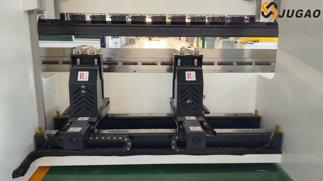
A CNC rendszer ezt a riasztást aktiválja, ha a hátsó mérőszegely nem éri el a rendszerbe programozott pozíciót.
Ezen eltérés tipikus okai:
• A golyós menetes orsó szennyeződése
• A szervohajtás túlterhelése
• Mechanikai akadályok a mozgási pályán
• A rendszerparaméterek helytelen kalibrálása
Ilyen esetekben ajánlom, hogy kézzel lassú sebességgel mozgassa el a tengelyt, és ellenőrizze, van-e abnormális ellenállás a mozgása során.
Lépésről lépésre történő hibaelhárítási protokoll a présfék CNC riasztáskódjaihoz
Ahelyett, hogy pánikba esnénk vagy impulzívan cselekednénk egy riasztásra, egy strukturált, szisztematikus hibaelhárítási folyamat követése kulcsfontosságú az hatékony megoldáshoz.
1. lépés: A gép működésének biztonságos leállítása
Bármilyen ellenőrzés vagy hibaelhárítási munka megkezdése előtt mindig győződjön meg arról, hogy a gépet teljesen kikapcsolták a biztonságos üzemeltetési eljárásoknak megfelelően. A biztonság minden karbantartási tevékenység elsődleges prioritása.
2. lépés: Külső és egyszerű kiváltó tényezők ellenőrzése
Először a legnyilvánvalóbb és külső összetevőket ellenőrzöm, amelyek kiválthatják a riasztást, ideértve:
• Vészleállító gombok (véletlen aktiválás esetén)
• Biztonsági fényfüggönyök (akadályok vagy hibák esetén)
• Áramköri megszakítók az elektromos szekrényben (kioldás esetén)
• Hidraulikaolaj-szintmutatók (alacsony szint esetén)
Meglepően sok riasztás a biztonsági áramkör hibái miatt keletkezik, nem pedig jelentős mechanikai vagy hidraulikus rendszerhibák miatt.
3. lépés: Az összes elektromos csatlakozási pont vizsgálata
A laza vezetékek a leggyakoribb okai a szakadozó riasztáskódoknak. A következő kritikus csatlakozási pontokat vizsgálom ki különösen alaposan:
• Szervohajtás-csatlakozók
• Kódolókábelek és azok csatlakozásai
• Elektromos klemmasorok
A gép folyamatos rezgése idővel ezeket a kapcsolatokat lazíthatja, ami jelzészavarokhoz és riasztásokhoz vezethet.
4. lépés: A hidraulikus rendszer stabilitásának ellenőrzése
Az autonóm nyomásmérő segítségével ellenőrizze, hogy a hidraulikus rendszer eléri-e a névleges üzemi nyomását. Ha a nyomás nem elegendő, vizsgálja meg az alábbi komponenseket:
• A hidraulikus szivattyú működési állapotát
• A biztonsági szelep kalibrálási beállításait
• A hidraulikus olajban esetlegesen jelen lévő szennyeződések jelenlétét
5. lépés: A CNC-paraméterek alapos átvizsgálása
A CNC-rendszer paramétereinek helytelen beállítása gyakori oka a tartós, ismétlődő riasztásoknak. Szükség esetén hasonlítsa össze a jelenlegi paraméterbeállításokat a gyártó által megadott eredeti gyári kalibrációs paraméterekkel.
Hatékony intézkedések a gyakori présfék CNC-riasztáskódok megelőzésére
A megelőző karbantartás mindig költséghatékonyabb és hatékonyabb, mint a reaktív javítás, és ez érvényes a gépvezérelt hajlítógépek CNC-riasztásainak csökkentésére is.
Rendszeres megelőző karbantartás bevezetése
A rendszeresen ütemezett rutinellenőrzések és karbantartások közvetlenül csökkentik a riasztási kódok gyakoriságát. Az alábbi fő karbantartási feladatokat ajánlom:
• Lineáris skálák rendszeres tisztítása a szennyeződés megelőzése érdekében
• Hátsó mérőcsavarok golyóscsapágyainak időben történő kenése
• Hidraulikus olajszűrők ütemezett cseréje
• Hűtőventilátorok rutinellenőrzése a megfelelő működés érdekében
Az elektromos szekrények tisztaságának és szellőzésének fenntartása
A porlerakódás az elektromos szekrények belsejében vezethet alkatrészek túlmelegedéséhez és elektromos jelzavarokhoz – mindkettő fő okozója a riasztási kódoknak. A megfelelő szellőzés biztosítása nemcsak a riasztások számát csökkenti, hanem meghosszabbítja a kritikus alkatrészek, például a szervohajtások élettartamát is.
Képezze a kezelőket az alapvető riasztási logika megértésére
Elengedhetetlen, hogy az üzemben dolgozó operátorokat képezzék arra, hogy felismerjék és megkülönböztessék a különböző típusú riasztási kódokat, ideértve:
• Tengelyszinkronizációs riasztások
• Biztonsági kapcsolóriasztások
• Hidraulikus nyomás-riasztások
A riasztási logika alapvető ismerete megakadályozza a felesleges pánikot a riasztások bekövetkeztekor, és csökkenti a tervezetlen leállásokat, mivel lehetővé teszi az operátorok számára, hogy kezdeti, megfelelő intézkedéseket tegyenek.
Gyakran feltett kérdések (FAQ)
Mi a közvetlen teendő, ha megjelenik egy présfék CNC-riasztási kód?
Először biztonságos módon állítsa le a gépet, majd jegyezze fel pontosan a riasztási üzenetet és a kód számát, és azonosítsa a riasztáshoz tartozó rendszermodult, mielőtt bármilyen további hibaelhárítási lépést megtenne.
Lehetséges-e a présfék CNC-riasztási kódok visszaállítása anélkül, hogy megoldanák az alapvető problémát?
Bár egyes riasztókódokat ideiglenesen el lehet tüntetni a rendszer újraindításával, a riasztás elkerülhetetlenül ismét meg fog jelenni, ha az alapvető okot nem szüntetik meg. Mindig azt javaslom, hogy a riasztás újraindítása előtt alapos diagnosztikai vizsgálatot végezzenek az alapvető hiba kiküszöbölése érdekében.
A Press Brake CNC riasztókódok eltérnek a Delem és az ESA rendszerek között?
Igen, a két rendszer eltér egymástól a riasztókódok számozását és a riasztások megjelenítésére szolgáló felhasználói felületet illetően. Azonban a tengelyvezérlés, a hidraulikus nyomás és a biztonsági áramkörök riasztásainak alapvető logikája lényegében megegyezik mindkét rendszerben.
Milyen stratégiák csökkenthetik a CNC riasztókódok megjelenésének gyakoriságát?
A rendszeres megelőző karbantartás bevezetése, a mechanikus alkatrészek megfelelő és időben történő kenése, a hidraulikus rendszer nyomásának stabil tartása, valamint az elektromos rendszer tisztaságának és pormentességének biztosítása a leghatékonyabb stratégiák a CNC riasztókódok megjelenésének gyakoriságának jelentős csökkentésére.
Összegzés
A présfékekre szerelt CNC-riasztókódok megértése nem egy véletlenszerű számokból álló lista megtanulását jelenti – hanem az alapul szolgáló rendszerlogika megértését, amelyet minden egyes kód képvisel. Gyakorlati tapasztalat alapján a riasztókódok túlnyomó többsége korai figyelmeztető jele potenciális problémáknak, nem pedig katasztrofális, visszaállíthatatlan géphibáknak.
Egy strukturált hibaelhárítási folyamat követésével – a pontos kód és üzenet feljegyzésével, a megfelelő rendszermodul azonosításával, valamint egy szisztematikus ellenőrzéssel – a riasztással kapcsolatos problémákat gyorsan és biztonságosan el lehet hárítani, így minimalizálva a termelés leállásának idejét.
Ha ismétlődő CNC riasztási kódokkal küzd, amelyeket az alapvető hibaelhárítási lépésekkel nem sikerül megoldani, vagy ha szakmai műszaki támogatásra van szüksége, ajánljuk, hogy lépjen kapcsolatba egy specializált mérnöki csapattal. A pontos szakmai diagnózis és a rendszeres megelőző karbantartás nemcsak csökkenti a tervezetlen gyártási leállásokat, hanem védi a sajtógép berendezése hosszú távú működési pontosságát és megbízhatóságát is.

