


CYBELEC CybTouch 12 eszközkezelési szakértői tanácsok
Tartalomjegyzék
• Bevezetés
• Dörzscsappantyú-konfiguráció
• Lépésről lépésre: dörzscsappantyú létrehozása és módosítása
• Matrica-konfiguráció
• Lépésről lépésre: matrica létrehozása és módosítása
• Szabványosított szerszám-elnevezési konvenciók
○ Dörzscsappantyú-elnevezési szabályok
○ Matrica-elnevezési szabályok
• Hátsó mérőszeg működése és biztonsága
• GYIK (Gyakran Ismételt Kérdések)
○ Hogyan optimalizálható a CYBELEC CybTouch 12 eszközkezelési teljesítmény?
○ Mit tegyünk, ha a rendszer nem ismer fel egy eszközt?
○ Testreszabhatók-e az eszközbeállítások a rendszerben?
• Következtetés
Az hatékony eszközkezelés a leegyszerűsített CNC megmunkálási műveletek alapköve, és ennek elsajátítása a CYBELEC CybTouch 12 rendszerhez kulcsfontosságú a fémfeldolgozás pontosságának és termelékenységének növeléséhez. Ez az útmutató gyakorlatias, közvetlenül alkalmazható stratégiákat mutat be a CybTouch 12 platformon történő eszközkezelésre, mind az új felhasználók számára, akik éppen megismerkednek a rendszerrel, mind a tapasztalt gépkezelők számára, akik munkafolyamataikat szeretnék finomhangolni. Az itt leírt irányelvek követésével teljes mértékben kihasználhatja a rendszer eszközkezelési funkcióit, és minimalizálhatja hibáit a hajlítási folyamatokban.
Bevezetés
A CYBELEC CybTouch 12 eszközkezelési modulja lehetővé teszi a felhasználók számára, hogy létrehozzák és konfigurálják a gépi szerszámokat – ez alapvető lépés a pontos hajlítási számítás és végrehajtás érdekében. A megfelelő ütő- és nyomószerszám kiválasztása és beállítása után az üzemeltetőknek csupán a kívánt hajlítási szöget és a perem hosszát (L) kell megadniuk. A CybTouch 12 rendszer ezután automatikusan kiszámítja a hajlításhoz szükséges pontos X- és Y-tengely pozíciókat, így minden megmunkálási műveletnél konzisztens pontosságot garantál.
Ütőszerszám-konfiguráció
Alapvető kiválasztási utasítások
Egy előre konfigurált ütőszerszám kiválasztásához navigáljon a rendszer ütőszerszám-könyvtárában az interfész nyilbillentyűivel, majd térjen vissza a Hajlítási számítási oldalra a kiválasztás alkalmazásához.
Lépésről lépésre: ütőszerszám létrehozása és módosítása
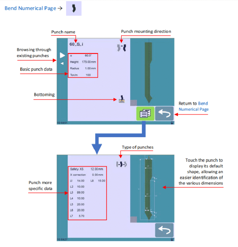
Ha a rendszerben még nem lett létrehozva lyukasztó, akkor a lyukasztó mező alapértelmezett címként "???"-t jelenít meg. A meglévő lyukasztókönyvtárak esetében a rendszer automatikusan kiválasztja az utoljára használt lyukasztót (pl. 60_S_i); figyelem, bármilyen módosítás nem írja felül az eredeti lyukasztót, mivel a szerkesztett beállítások új egyedi név alatt kerülnek mentésre. Kövesse az alábbi 13 lépést a lyukasztó létrehozásához vagy módosításához:
1. Érintse meg a lyukasztó ikont a lyukasztó részletes konfigurációs felület megnyitásához.
2. Adja meg az új lyukasztó alapvető fizikai paramétereit: lyukasztó szöge (α), magassága, sugara és tonna/méter (ton/m).
3. Használja a Lyukasztó felszerelési iránya gombot a lyukasztó megfordításához, ha a megmunkálási beállítás ezt igényli.
4. Válassza ki a Lefúrás ikont, hogy a lyukasztót kopásálló eszközként jelölje meg lefúrásos műveletekhez.
5. Érintse meg a Menü gombot az Egyéb oldal eléréséhez a speciális paraméterbeállításokhoz.
6. Használja a Lyukasztó típusa ikont a lyukasztó szerkezeti típusának kiválasztásához: egyenes, normál vagy hattyúnyakú.
7. A részletes méretadatok (L1–Lx) megadásához használja a képernyő jobb oldalán található grafikus eszközábrát. A grafikus elemre koppintva az eszköz alapértelmezett méretelrendezése töltődik be, ami egyszerűsíti az egyes paraméterek azonosítását és bevittetését.
Az L1–Lx méretszabványok megegyeznek a PC 1200, a DNC 880S és a ModEva rendszerekben használtakkal. A különböző rendszerek közötti eszközök átviteléhez exportálja a paraméterlistákat a PC1200-ból, és használja azokat a CybTouch 12 programozására – az egyetlen eszközök egységes kezelése érdekében javasoljuk, hogy azonos neveket adjon minden rendszerben ugyanazon eszközöknek.
8. Adja meg a kritikus biztonsági és kalibrációs értékeket:
○ Biztonsági XS: A lyukasztó és a hátsó mérőlécek közötti biztonságos távolság az X-tengely mentén.
○ X-korrekció: Kalibrációs érték a lyukasztó esetleges elmozdulásának kiegyenlítésére.
9. Térjen vissza az előző konfigurációs oldalra (a rendszerben bármely eszközkonfiguráció mentéséhez második szintű hozzáférési jelszó szükséges).

10. Érintse meg az aktuális lyukasztó nevét (pl. 60_S_i) a mentési folyamat elindításához.
11. Válassza a „Metsző mentése” lehetőséget a meglévő szerszámparaméterek felülírásához, vagy a „Metsző mentése másként” lehetőséget a módosított/új metsző egyedi név alatt történő tárolásához.
12. Használja a rendszer alfanumerikus billentyűzetét az új metsző névének megadásához, és tartsa be a következő szakaszban ismertetett szabványos elnevezési konvenciókat.
13. Érintse meg a
visszatérés gombot a fő programoldalra való visszatéréshez; az újonnan elmentett metsző előre kiválasztva jelenik meg, és azonnal használatra kész a megmunkálási műveletekhez.
Doboz konfiguráció
Alapvető kiválasztási utasítások
A doboz kiválasztása ugyanazt a folyamatot követi, mint a metsző kiválasztása: böngéssze a rendszer előre tárolt dobozkönyvtárát a nyilbillentyűk segítségével, majd térjen vissza a hajlítási numerikus oldalra a kiválasztás megerősítéséhez.
Lépésről lépésre: doboz létrehozása és módosítása
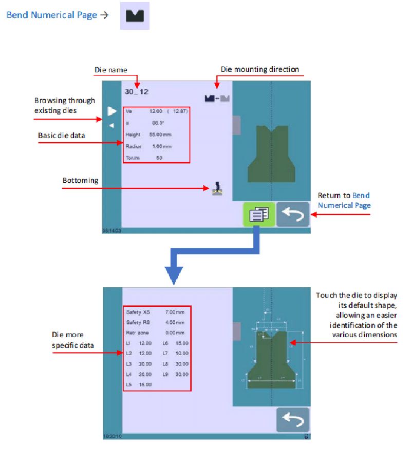
Ha a rendszerben nincs beállítva nyomószerszám, akkor a nyomószerszám mező „???” jelet fog mutatni; meglévő nyomószerszám-könyvtárak esetén a rendszer az utoljára használt nyomószerszámot tölti be (pl. 30_12). Egy meglévő nyomószerszám módosítása nem befolyásolja az eredeti paramétereket, mivel minden változtatás új név alatt kerül mentésre. Végezze el az alábbi 12 lépést egy nyomószerszám létrehozásához vagy módosításához:
1. Érintse meg a nyomószerszám ikont a nyomószerszám-részletek konfigurációs felületének megnyitásához.
2. Adja meg az új nyomószerszám alapvető fizikai paramétereit: nyomószerszám-szélesség (Ve), szög (α), magasság, sugár és tonna/méter (Ton/m).
3. Használja a Nyomószerszám felszerelési iránya gombot a nyomószerszám megfordításához, ha ezt a megmunkálási beállítás igényli.
4. Válassza ki a Lefúrás ikont, hogy a nyomószerszámot kopásálló eszközként sorolja be a lefúrásos folyamatokhoz.
5. Érintse meg a MENÜ gombot a További oldal megnyitásához, ahol részletesebb méret- és biztonsági beállítások érhetők el.
6. A részletes méretek (L1–Lx) megadásához tekintse meg a képernyő jobb oldalán található grafikus sablonábrát. Az ábra érintése megjeleníti a sablon alapértelmezett méretelosztását, így könnyebben adhatja meg a pontos értékeket.
A sablonokhoz hasonlóan a sablonok L1–Lx méretei is megfelelnek a PC 1200, a DNC 880S és a ModEva rendszerek szabványainak. A keresztrendszeres szerszám-kompatibilitás érdekében exportálja a sablonparamétereket a PC1200-ból, és használja azokat a CybTouch 12 programozásához; azonos sablonok esetén ugyanazokat a neveket használja minden rendszerben.
7. Adja meg a speciális biztonsági és üzemeltetési értékeket:
○ Biztonsági XS: A sablon és a hátsó mérőszeg közötti biztonságos távolság az X-tengely mentén.
○ Biztonsági RS: A sablon és a hátsó mérőszeg közötti biztonságos távolság az R-tengely mentén.
○ Visszahúzási zóna: A sablon működés közben előre beállított visszahúzási zónája.
8. Térjen vissza az előző konfigurációs oldalra (a sablonkonfigurációk mentéséhez szükséges a 2. szintű jelszó).
9. Érintse meg az aktuális sablon nevét (pl. 30_12), hogy elindítsa a mentési folyamatot.
10. Válassza a „Minta mentése” lehetőséget az eredeti minta paramétereinek felülírásához, vagy a „Minta mentése másként” lehetőséget a módosított/m új minta egy egyéni név alatt történő tárolásához.
11. Használja az alfanumerikus billentyűzetet az új minta nevének megadásához a rendszer szabványos elnevezési szabályai szerint.
12. Érintse meg a
visszatérés gombot a főprogramoldalra való visszatéréshez; az újonnan elmentett minta előre kiválasztva jelenik meg, és azonnali használatra kész.
Szabványos eszköz-elnevezési konvenciók
A dörzscsavarok és minták egységes elnevezési konvenciójának alkalmazása elengedhetetlen a CYBELEC CybTouch 12-es gépen az eszközök hatékony kezeléséhez. Egy átlátható, egységes elnevezési rendszer lehetővé teszi minden eszköz gyors és pontos azonosítását a könyvtárban, és a csapatok további egyedi szabályokat is bevezethetnek a saját gyártási igényeik alapján, hogy tovább növeljék a szervezeti hatékonyságot és csökkentsék az eszközválasztási hibákat.
Dörzscsavar-elnevezési szabályok
A dörzscsavarok neve három egymást követő részből álljon: dörzscsavar-szög → dörzscsavar-típus → fordítottság állapota.
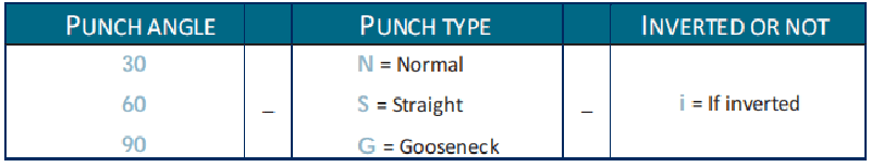
Dörzscsavar-típus rövidítései:
• N = Normál
• S = Egyenes
• G = Lúdnyak
Fordítás rövidítése:
• i = Fordított (ha a lyukasztó a szokásos, nem fordított helyzetben van, akkor hagyja el ezt a rövidítést)
Példák: 90_N_i, 60_G, 30_S
Mátrixnevek szabályai
A mátrixnevek ugyanolyan strukturált formát követnek, mint a lyukasztók: mátrixszélesség (Ve méret) → mátrixszög → fordítás állapota. Ugyanazt a fordítás rövidítést használja a mátrixokhoz is (i = fordított), és hagyja el a rövidítést, ha a mátrix az alap felszerelési helyzetben van.
Példák: 12_86_i, 16_86, 20_30
Hátsó mérőszeg működése és biztonsága
A hátsó mérőszeg ciklusfunkciója egy alapvető funkció a biztonságos és hatékony szerszámmenedzsment érdekében a CYBELEC CybTouch 12-es gépen, amelyet kifejezetten a hátsó mérőszeg beállításaira terveztek. Ez a funkció teljesen előre mozgatja a hátsó mérőszegket, lehetővé téve az operátorok számára a szükséges kalibrációs és beállítási munkákat anélkül, hogy kezüket vagy karjukat a gép szerszámai közé kellene helyezniük – így megszüntetve egy kulcsfontosságú biztonsági kockázati tényezőt a megmunkálási folyamatban.
Fontos megjegyzés: A hátsó mérőszeg ciklusfunkció láthatósága és elérhetősége a gép jelenlegi konfigurációjától és indexelési állapotától függ, és nem minden működési módban érhető el.
Lépésről lépésre: A hátsó mérőszeg ciklus működtetése
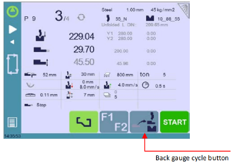
1. Győződjön meg arról, hogy a gép megfelelően indexelve van; ha az indexelés befejezetlen, a hátsó mérőszeg ciklus gomb szürkén jelenik meg, és nem használható.
2. Nyomja meg és tartsa lenyomva a hátsó mérőszeg ciklus gombot legalább 2 másodpercig a funkció aktiválásához.
3. A hátsó mérőszegek a teljes előreállított pozícióba mozognak, a szúró és a kivágó közé. Ha a gép hídja nem a Felső HoltPonton (TDC) van, akkor először teljesen felfelé mozog, majd indulnak el a hátsó mérőszegek.
4. Miután befejezte az összes hátsó mérőszeg-beállítást, nyomja meg újra a ciklus gombot a funkció kikapcsolásához, majd nyomja meg a START gombot a gép normál működésének folytatásához.
Gyakran feltett kérdések (FAQ)
Hogyan optimalizálható a CYBELEC CybTouch 12 eszközkezelési teljesítménye?
A CybTouch 12-es eszközkezelő modul maximális teljesítményének biztosításához minden eszközt pontosan azonosítani és teljes körűen paraméterezni kell a könyvtárban, naprakész fizikai és működési adatokkal. Rendszeresen ellenőrizze az eszközadatok pontosságát, és győződjön meg arról, hogy az eszközbeállítások kompatibilisek a gép általános konfigurációjával – ez biztosítja az eszközök és a megmunkálási műveletek zavartalan integrációját, és minimalizálja a leállásokat.
Mit tegyünk, ha a rendszer nem ismer fel egy eszközt?
Ha a CYBELEC CybTouch 12 nem érzékeli egy lyukasztó vagy kivágó szerszámot, először ellenőrizze, hogy a szerszám megfelelően van-e behelyezve, és mechanikailag jól van-e beállítva a gépen. Ezután ellenőrizze az eszköz paramétereit a rendszer eszközkezelő felületén, és szükség esetén írja újra vagy javítsa ki a pontatlan adatokat. Végül győződjön meg arról, hogy a rendszer szoftvere a legújabb verzióra frissült, hogy elkerülje az esetleges szoftver–szerszám kompatibilitási problémákat.
Testreszabhatók-e az eszközbeállítások a rendszerben?
Igen, a CYBELEC CybTouch 12-es modellnél teljes mértékű egyéni beállítás érhető el az eszközparaméterekhez. A szerszámkezelő felületen módosíthatók az összes releváns paraméter, például a dörzstüske/lyukasztó fizikai méretei, a megmunkálandó alkatrész anyagtípusa és a korrekciós értékek, hogy azok pontosan illeszkedjenek a megmunkálási műveletek specifikus követelményeihez. Ügyeljen arra, hogy minden egyéni beállítást megfelelően mentse el a rendszerben, így biztosítva a gyártási sorozatokon belüli eredmények konzisztenciáját.
Összegzés
A CYBELEC CybTouch 12-es modell szerszámkezelési funkcióinak elsajátítása a rendszer alapvető működési jellemzőinek átfogó ismeretét, egy jól strukturált szerszámkönyvtárat, valamint az összes szerszámkonfiguráció rendszeres karbantartását és frissítését igényli. Ennek az útmutatónak a lépésről lépésre leírt irányelvei, a névadási szabályzatok és a biztonsági protokollok alkalmazásával hatékonyan leegyszerűsítheti a CNC megmunkálási folyamatát, jelentősen csökkentheti a működési hibák előfordulását, és növelheti mind a fémfeldolgozási folyamatok pontosságát, mind azok hatékonyságát.
Személyre szabott támogatásért, gépe teljesítményének maximalizálásáért vagy speciális szerszámgazdálkodási kihívások kezeléséért lépjen kapcsolatba műszaki támogatási csapatunkkal. Emellett tekintse meg kapcsolódó műszaki dokumentumainak gyűjteményét, hogy mélyítsen szakértelemét, és kihasználja a CYBELEC CybTouch 12 szerszámgazdálkodási rendszer teljes lehetőségeit.

