


Alapvető kezdőútmutató az ESTUN E300 programozásához
Ha most ismerkedik az ESTUN E300 programozásával, ez az útmutató éppen Önnek készült. Számos új felhasználó szeretné kihasználni ezen rendkívül rugalmas vezérlőrendszer teljes lehetőségeit, és ez a cikk végigvezeti Önt a legfontosabb kezdői tippekkel, hogy elindítsa programozási útját. Hatékonyságáról és rugalmasságáról híres az ESTUN E300 vezérlőrendszer, amelyet megbízható alapvető ismeretek birtokában könnyen elsajátíthat – ez az útmutató éppen ezt a szilárd alapot nyújtja Önnek, akár a programozási pontosság növelését célozza, akár egyszerűen meg szeretné érteni a rendszer alapműveleteit.
Tartalomjegyzék
1. Felület oldalstruktúra
2. Egylépéses programozás
3. Többlépéses programozás
4. Kézi tengelymozgatás
5. Hajlítószerszám-paraméterek konfigurálása
6. Hajlítási korrekciós módszerek
7. Gyakran Ismételt Kérdések (GYIK)
○ Gyakori programozási hibák elhárítása
○ A programozási kimenet pontosságának javítása
8. Záró
Felületi oldal szerkezete
Az ESTUN E300 programozási felületének oldalszerkezetének megértése kulcsfontosságú a zavartalan navigációhoz és működéshez. Miután bekapcsolta az eszközt, és megvárta a rendszer betöltődését, a képernyő automatikusan megjeleníti az alapértelmezett egylépéses oldalt. Az egész felület öt alapvető szekcióból áll, mindegyiknek meghatározott funkcionális szerepe van, és az egyes részek ismerete elengedhetetlen az alapműveletek végrehajtásához.
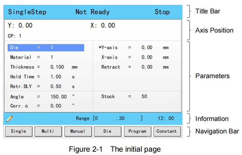
Cím-sor
Ez a szekció minden felületi oldalon látható, és megjelenített tartalma balról jobbra rögzített: Oldal neve, Rendszerállapot és Működési mód.
• Oldal neve: Megjeleníti az aktuális működési oldal nevét, például SingleStep, Multi vagy Program.
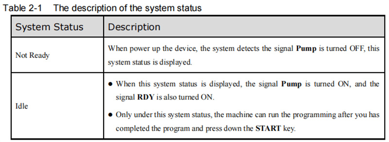
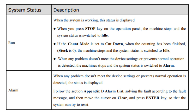
• Rendszerállapot: Megjeleníti a rendszer valós idejű működési állapotát; az ESTUN E300 esetében összesen hat különböző állapotlehetőség létezik.
• Működési mód: A készülék jelenlegi működési módját jelzi, három különböző mód választható.
Tengelypozíció-kijelzés
Ez a terület a gép tengelyeinek valós idejű pozícióértékeit mutatja, ami alapvető fontosságú a pontos hajlítási vezérlés eléréséhez. A szabványos ESTUN E300 készülék alapértelmezés szerint X- és Y-tengely-vezérlési funkciókkal rendelkezik; továbbfejlesztett tengelyvezérlési funkciókhoz ajánlott az hivatalos ESTUN technikai támogatási csapatával kapcsolatba lépni.
Paraméterek területe
Ez a szakasz a jelenlegi működési oldalhoz tartozó paraméterinformációkat jeleníti meg – minden funkcionális oldal saját, egyedi beállítható paraméterkészlettel rendelkezik, amelyek itt egyértelműen jelennek meg gyors áttekintés és szerkesztés céljából.
Információs szakasz
Az ESTUN E300 felületén ez a rész részletesen felsorolja minden konfigurálható paramétert, beleértve a szerkeszthető értéktartományokat és a jelenleg beállított értékeket. A rendszeridő is ebben a szakaszban jelenik meg, a jobb oldalon, hogy könnyen hozzáférhető legyen a programozás és a működtetés során.
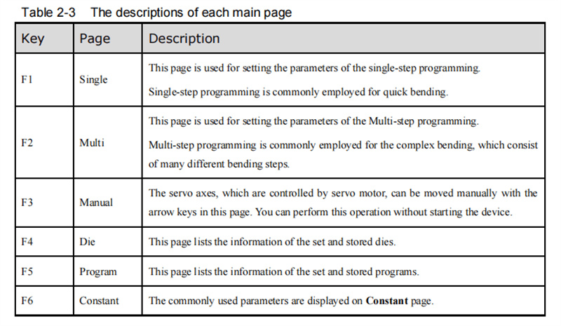
Navigációs sáv
A navigációs sáv megfelel az üzemeltetőpanel F1–F6 funkcióbillentyűinek, és lehetővé teszi a rendszer fő funkcionális oldalai közötti egyklikkes váltást. A kulcsok egyes funkcióinak és a hozzájuk tartozó oldalak leírásának részleteit lásd a hivatalos ESTUN E300 felhasználói kézikönyv 2–3. táblázatában. A navigációs sáv használatának elsajátítása egy alapvető készség, amely egyszerűsíti az összes további programozási műveletet.
Az említett oldalszerkezet ismerete lehetővé teszi, hogy hatékonyan navigáljon az ESTUN E300 különböző funkciói és beállításai között, így megbízható alapot teremt egy zavartalan programozási élményhez.
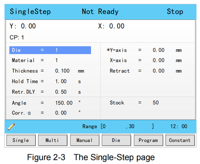
Egylépéses programozás
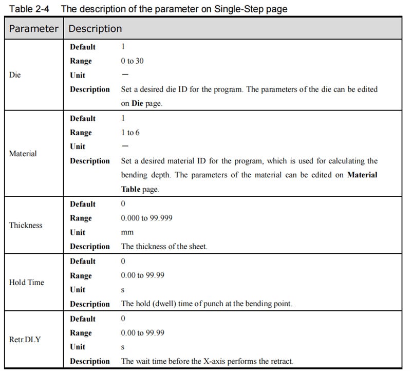
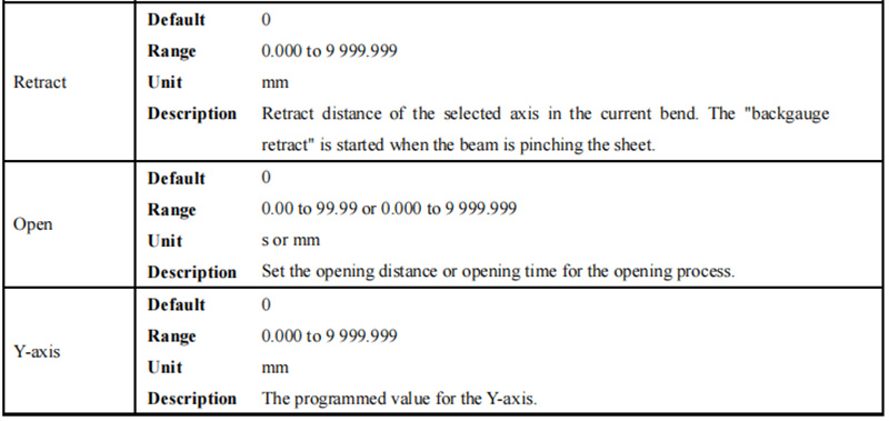
Az egylépéses programozás az ESTUN E300 alapértelmezett funkcióoldala (a bekapcsolás után azonnal megjelenik), és különösen a gyors hajlítási műveletekhez lett kialakítva, amelyekhez csak egyetlen hajlítási paraméterkészlet szükséges. Ezt az oldalt manuálisan is elérheti az üzemeltetőpanelen található F1 funkcióbillentyű lenyomásával. A felhasználói kézikönyv 2–4. táblázata részletesen ismerteti ezen oldal összes beállítható paraméterét, amely hasznos segédanyag a paraméterek szerkesztéséhez.
Gyakorlati programozási példa
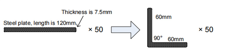
Vegyük példaként egy 120 mm-es acéllemez hajlítását, és részletesen ismertessük az egylépéses programozás folyamatát.
A fő hajlítási követelmények: X-tengely pozíciója 60 mm-re van beállítva, hajlítási szög 90°, az acéllemez vastagsága 7,5 mm, és a nyersanyag-érték 50. Szögbázisú programozást alkalmazunk, a matrica azonosítója (die ID) 1-re van állítva. A gyakorlati működési tapasztalatok alapján további segédtechnológiai paramétereket is beállítunk: tartási idő 3 másodperc, visszahúzási késleltetés 2 másodperc, és visszahúzási távolság 5 mm.
A konkrét programozási lépések a következők:
1. Lépjen a 'Die' paraméterhez, és adja meg az értéket: 1;
2. Válassza ki a 'Material' paramétert, és adja meg az értéket: 1;
3. Keresse meg a 'Thickness' paramétert, és adja meg az értéket: 7,5;
4. Állítsa a 'Hold Time' paramétert 3-ra;
5. Adja meg a 'Retr. DLY' (visszahúzási késleltetés) paraméternél az értéket: 2;
6. Állítsa az X-tengely pozíciójának paraméterét 60-ra;
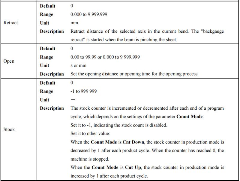
7. Adja meg a 'Retract distance' paraméternél az értéket: 5;
8. Válassza ki a 'Angle' paramétert, és adja meg az értéket: 90;
9. Állítsa a 'Stock' paramétert 50-re.
A művelet megkezdése előtt győződjön meg arról, hogy a Constant (Állandó) oldalon a Számlálási mód (Count Mode) Cnt Down (Lefelé számlálás) beállításra van állítva. Végül nyomja meg a START gombot a műveleti panelen – a szervó tengely automatikusan elvégzi a pozíciókalibrációt, és a gép a kalibráció befejezése után készen áll a hivatalos gyártásra.
Többlépcsős programozás
A többlépcsős programozás összetett hajlítási folyamatokhoz használatos, amelyek több különböző hajlítási paraméter- és lépcsőkészletet igényelnek, és erre a funkcionális oldalra a F2 funkcióbillentyű lenyomásával léphet be.
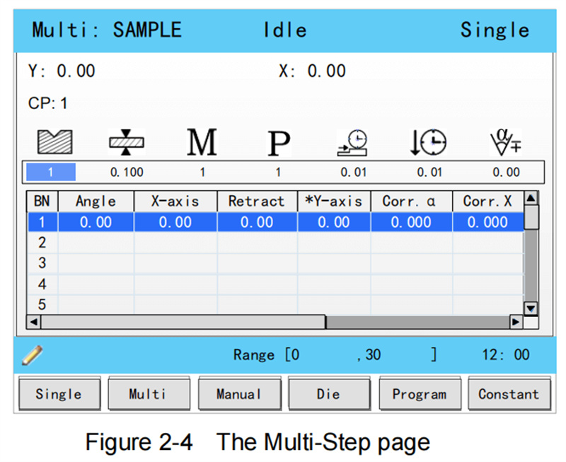
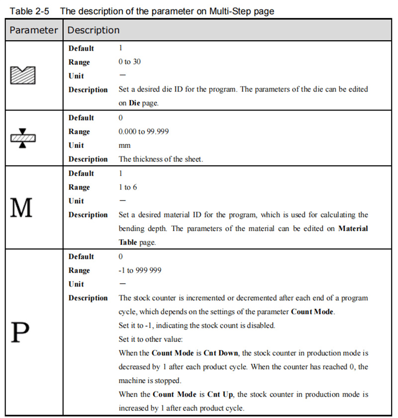
Ezen az oldalon található összes paraméter részletes leírása a hivatalos felhasználói kézikönyv 2–5. táblázatában található, amelyet a paraméterek beállítása és szerkesztése során is konzultálhat.
Gyakorlati programozási példa
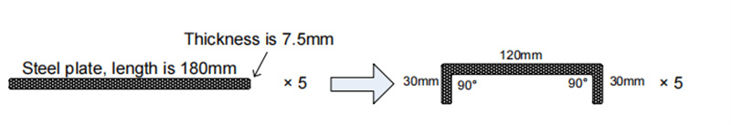
Az acéllemez hajlításával, amelynek hossza 180 mm, bemutatjuk a többlépéses programozási folyamatot. Ez a hajlítási feladat két külön lépést igényel: az acéllemez 120 mm-es és 30 mm-es szakaszainak 90°-os hajlítása, a lemez vastagsága 7,5 mm, a kiindulási érték (stock) 50 mm. Szögből történő programozást alkalmazunk, a nyomószerszám azonosítóját (die ID) 1-re állítjuk, és ugyanazokat a segédtechnológiai paramétereket konfiguráljuk, mint az egylépéses példában: tartási idő 3 másodperc, visszahúzási késleltetés 2 másodperc, visszahúzási távolság 5 mm (anyagtípus beállítva acélra, értéke 1).
A konkrét programozási lépések a következők:
1. Mozgassa a kurzort a Nyomószerszám (Die) paraméterhez, és adja meg az értéket: 1;
2. Állítsa a Vastagság (Thickness) paramétert 7,5-re;
3. Válassza ki az Anyag (Material) paramétert, és adjon meg 1-et;
4. Adja meg az Érték (Stock) paraméternél a 50-et;
5. Állítsa a Visszahúz. késleltetés (Retr. DLY) paramétert 2-re;
6. Adja meg a Tartási idő (Hold Time) paraméternél a 3-at;
7. Az első hajlítási lépésnél (BN 1) állítsa a Szög (Angle) paramétert 90°-ra;
8. A BN 1 esetében állítsa az X-tengely pozíciójának paraméterét 30-ra;
9. A BN 1 esetében adja meg a Visszahúzási távolság (Retract distance) paraméternél az 5-öt;
10. Erősítse meg az első lépés összes paraméterét az ENTER billentyű lenyomásával;
11. Egy felugró párbeszédpanel kéri Önt, hogy hozzon létre egy új hajlítási lépést – kattintson az OK gombra a megerősítéshez;
12. A második hajlítási lépéshez (BN 2) állítsa be az X-tengely pozíciójának paraméterét 120-ra;
13. A BN 2 esetében állítsa be a visszahúzás távolságának paraméterét 5-re;
14. Nyomja meg a START gombot a kezelőpanelen a többlépéses hajlítási folyamat elindításához.
Az előbbi beállítások után az ESTUN E300 szervó tengelye automatikusan elvégzi minden egyes hajlítási lépés pozíciókalibrálását, és a gyártás megkezdhető, amint a gép készen áll.
Kézi tengelymozgatás
A kézi tengelymozgás elsajátítása alapvető készség az ESTUN E300 kezeléséhez, mivel elengedhetetlen a berendezés hibakereséséhez és a szervotengelyek finom pozícionálásához. A szervotengelyek szervomotorokkal vannak meghajtva, és kézi mozgatásuk a Kézi oldalon található nyilbillentyűkkel szabályozható – ez a művelet nem igényli a hivatalos gyártási folyamat elindítását, így ideális a működés előtti berendezés üzembe helyezéséhez.
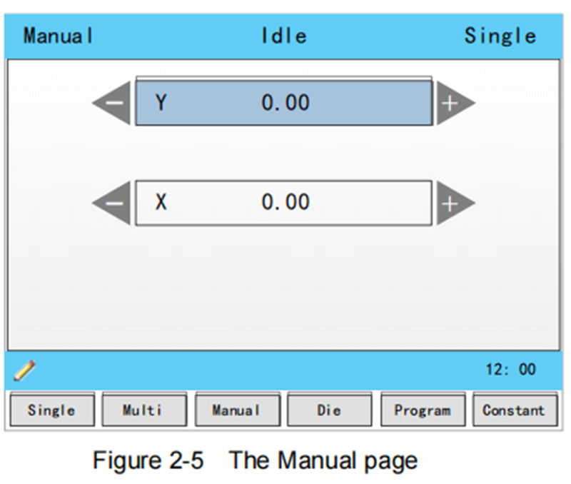
A Kézi oldalra a készülék bekapcsolása után az F3 funkcióbillentyű lenyomásával léphet be (a rendszer az alapértelmezett oldalt jeleníti meg). A kézi mozgatás működése egyszerű:
• Az UP (FEL) és DOWN (LE) nyilbillentyűkkel válassza ki a beállítani kívánt szervotengelyt;
• A LEFT (BALRA) és RIGHT (JOBBRA) nyilbillentyűkkel állítsa be a kiválasztott tengely mozgásirányát.
Ezen alapművelet elsajátítása biztosítja a gép pontos előzetes beállítását, és megtalálja az alapját a pontos hajlítási eredményeknek.
Dobozparaméterek konfigurációja
Szögből történő programozás alkalmazása esetén a hajtószerszám paramétereinek helyes beállítása az pontos hajtás előfeltétele. A hajtószerszám-paraméterek beállító oldalára a működtető panel F4 funkcióbillentyűjének megnyomásával léphet be, és a paraméterek beállítása a következőképpen történik:
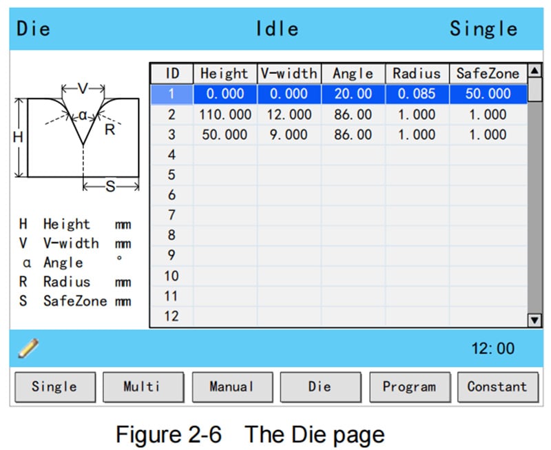
1. Nyomja meg a FEL és LE nyílbillentyűket a konfigurálandó hajtószerszám-azonosító kiválasztásához;
2. Nyomja meg a BALRA és JOBBRA nyílbillentyűket a kiválasztott hajtószerszám különböző beállítható paraméterei közötti váltáshoz;
3. Adja meg a szükséges paraméterértékeket a működtető panel számjegybillentyűivel.
A hajtószerszám műszaki paraméterei a felhasználói kézikönyv 2-7. ábráján láthatók, a fő paraméterek meghatározása a következő:
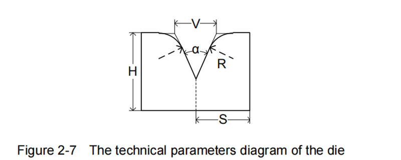
• H (Hajtószerszám magassága): A gép hajtásmélységének kiszámítására szolgál;
• V (V-nyílás szélessége): A hajtószerszám V-nyílásának metsző érintővonalai közötti távolság;
• α (Hajtószerszám szöge): A hajtószerszám V-nyílásának rögzített szöge;
• R (V-alakú nyílás élének görbületi sugara): A készülék V-alakú nyílásának élei lekerekítésének sugara;
• S (Biztonsági távolság): Kritikus paraméter az R-tengellyel felszerelt gépekhez, amely a működtető fogantyú és a készülék ütközésének megelőzésére szolgál. A minimális biztonsági távolságot a rendszer automatikusan kiszámítja a készülék méretei alapján a következő képlet szerint: S = FS + V/2 (FS = a V-alakú horpadás hátsó oldalán lévő sík szakasz; V = a készülék nyílásának értéke).
Hajlítási korrekciós módszerek
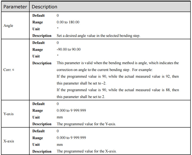
A pontos hajlítási eredmények elérése az ESTUN E300-as géppel a hajlítási korrekciós technikák elsajátításától függ. A gyártási folyamat megkezdése előtt feltétlenül el kell végezni a gép üzembe helyezését: programozzon egy egyszerű hajlítási folyamatot az Egylépéses oldalon, és futtasson le egy teljes hajlítási ciklust, majd mérje meg a munkadarab tényleges hajlítási szögét, hajlítási mélységét és hátsó irányzék távolságát. Hasonlítsa össze ezeket a tényleges értékeket a programozott beállított értékekkel annak eldöntéséhez, hogy szükség van-e korrekciós beállításokra. Az ESTUN E300 három alapvető korrekciótípust támogat: szöghelyesbítést, Y-tengely-korrekciót és X-tengely-korrekciót, mindegyiknek egyértelmű beállítási tartománya és működtetési módszere van.
Szöghelyesbítés
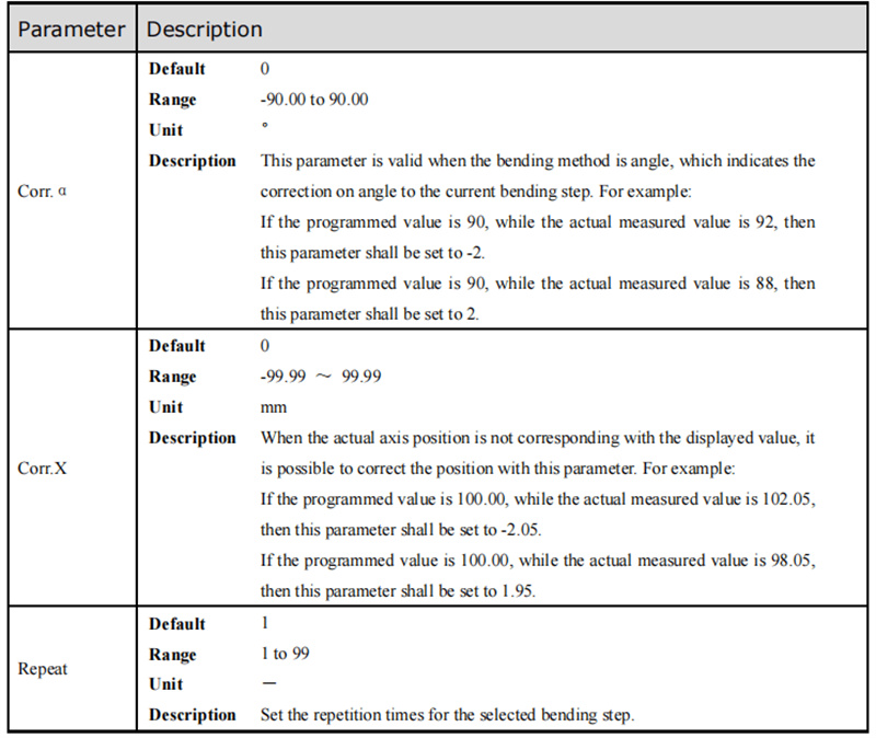
A szöghelyesbítési paraméter (Corr. α) beállítható tartománya -90 és 90 között van. Ha a munkadarab tényleges hajlásszöge nem egyezik meg a programozott kijelzett értékkel, akkor a torzulás értéke alapján végezzen helyesbítést: például ha a programozott szög 90°, de a ténylegesen mért szög 92°, akkor állítsa a Corr. α értékét -2-re; ha a ténylegesen mért szög 88°, akkor állítsa a Corr. α értékét 2-re a torzulás kiegyenlítéséhez.
Y-tengely helyesbítése
Az Y-tengely helyesbítési paramétere (Corr. Y) beállítható tartománya -99,999 és 99,999 között van, és a hajlítási mélység finomhangolására szolgál. Mélység-alapú programozás esetén optimalizálhatja a helyesbítés hatását úgy, hogy többször beállítja a Corr. Y értékét, gyűjtve a gyakorlati működési tapasztalatokat, és mérve a hajlítási mélység változását fokonkénti szögbeállítás esetén. Ez az iteratív beállítási folyamat biztosítja, hogy a tényleges hajlítási mélység megfeleljen a tervezési követelményeknek.
X-tengely helyesbítése
Az X-tengely korrekció (Corr. X) ugyanazt az alapvető logikát követi, mint a szögkorrekció, és a pontos hátsó irányzék pozíciójának beállításához -99,999 és 99,999 közötti beállítható paramétertartomány áll rendelkezésre. Például ha a programozott X-tengely pozíció 100,00 mm, de a ténylegesen mért pozíció 102,05 mm, akkor a Corr. X értékét -2,05-re kell állítani; ha a ténylegesen mért pozíció 98,05 mm, akkor a Corr. X értékét 1,95-re kell állítani.
Megjegyzés: Az egylépéses programozási módban a gépet bármikor meg lehet állítani a hajlítási folyamat során, és az X-tengely programozott értéke közvetlenül módosítható – ezért az egylépéses műveletekhez általában nem szükséges a Corr. X alkalmazása. A többlépéses programozás azonban több egymást követő hajlítási lépést foglal magában, és a Corr. X értéket minden lépéshez külön-külön lehet hozzárendelni célzott pozíciókorrekció céljából.
Gyakran feltett kérdések (FAQ)
Hogyan hárítsunk el gyakori hibákat az ESTUN E300 programozásában?
Amikor programozási vagy működési hibába ütközik az ESTUN E300 eszközön, az első lépés a képernyőn megjelenő hibakód ellenőrzése, valamint az hivatalos felhasználói kézikönyv hibakód-leírás és megoldási szakaszának tanulmányozása. Ugyanakkor ellenőrizze, hogy az eszköz minden hardveres csatlakozása biztonságosan rögzített-e, és hogy az összes folyamatparaméter megfelel-e a hajlítási követelményeknek. A felhasználói kézikönyv külön hibaelhárítási fejezete továbbá részletes megoldásokat nyújt a leggyakrabban előforduló hibákra, amelyek kulcsfontosságú forrásként szolgálnak a problémák megoldásához.
Hogyan növelhető az ESTUN E300 programozási kimeneteinek pontossága?
Az ESTUN E300 programozás hajlítási eredményeinek pontosságának javítása érdekében a berendezés rendszeres kalibrálása a legfontosabb intézkedés – a időben elvégzett kalibrálás biztosítja, hogy a gép tengelyei és érzékelői megtartsák pontos mérési és mozgási teljesítményüket. Emellett győződjön meg arról, hogy minden folyamat- és szerszámparamétert pontosan beállítottak a munkadarab adott hajlítási követelményei szerint, és igazítsa a korrekciós paramétereket (Corr. α, Corr. Y, Corr. X) az aktuális mérési eredmények alapján. A berendezés naponta végzett, következetes karbantartása (pl. mozgó alkatrészek kenése, érzékelők tisztítása) és a rendszer üzemeltető szoftverének időben történő frissítése is lényeges szerepet játszik a hosszú távú programozási és hajlítási pontosság fenntartásában.
Összegzés
Az ESTUN E300 alapműveleteinek és programozási készségeinek elsajátítása kulcsfontosságú a munkahatékonyság és a hajlítási pontosság javításához ezen vezérlőrendszerrel. Ez az útmutató áttekinti az összes lényeges kezdő ismeretet, ideértve a felület oldalszerkezetének megértését, az egylépéses és többlépéses programozás elsajátítását, a tengelyek kézi mozgatásának kezelését, a szerszámparaméterek beállítását, a hajlítási korrekciós technikák alkalmazását, valamint a gyakori hibák elhárítását. Az alapvető készségek megszilárdításával erős alapot teremt a jövőben az ESTUN E300 továbbfejlesztett programozási és üzemeltetési technikáinak elsajátításához.
Ha tovább szeretné bővíteni az ESTUN E300 készségeit, vagy konkrét, összetett programozási és hajlítási kihívásokat szeretne megoldani, ajánlott a részletes hivatalos műszaki dokumentáció tanulmányozása, illetve az ESTUN szakértő műszaki csapatával való kapcsolatfelvétel. A mélyebb működési útmutatásért vagy személyre szabott műszaki támogatásért további hivatalos dokumentációkhoz és anyagokhoz is hozzáférhet, amelyek folyamatos tanulást és készségfejlesztést tesznek lehetővé.

