


How to Operate the E21 NC Press Brake System with Maximum Efficiency
Table of Contents
1. Overview of the E21 System Operation Manual
2. Step 1: Hydraulic Oil Filling and Electrical Wiring Connection
○ Correct Filling of the Hydraulic Oil Tank
○ Power Connection for the NC Press Brake
○ Activating the Main Power Supply
○ Turning On the Machine’s Power Switch
○ Connecting the Foot Pedal Switch
○ Powering Up the E21 Press Brake
○ Correct Activation of the Pump Switch
○ Releasing the Emergency Stop on the Foot Pedal
○ Pressing the ENTER Key to Start the Machine
○ Verifying the Rotation Direction of the Main Motor
○ Clockwise Rotation = Normal Operation
○ Emergency Stop Operation
○ Correcting Wiring by Swapping Two Wires
3. Step 2: Machine Startup Procedure
○ Powering Up the E21 NC Press Brake
○ Proper Startup of the Hydraulic Oil Pump
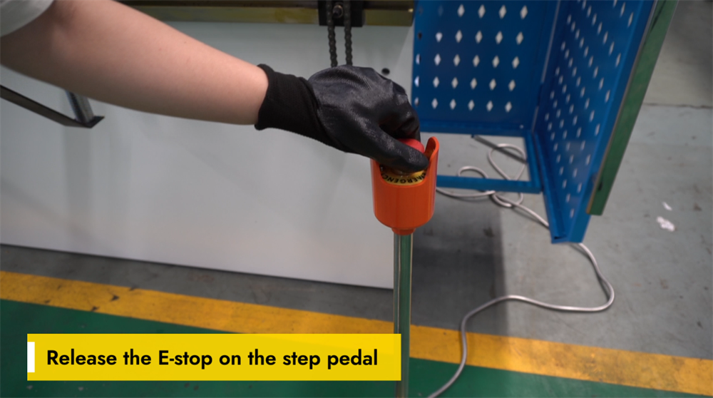
○ Releasing the Emergency Stop Switch
○ Releasing the E-Stop on the Foot Pedal
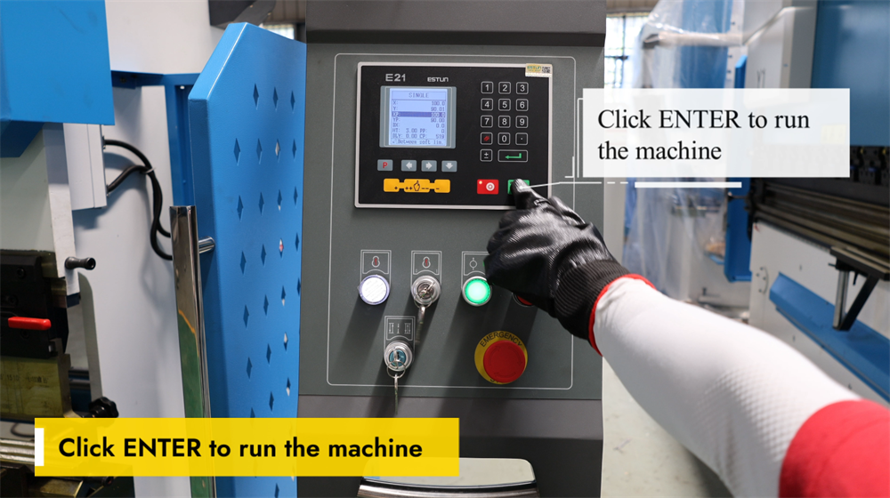
○ Initiating Press Brake Operation via the ENTER Key
4. Step 3: Explanation of Operational Modes
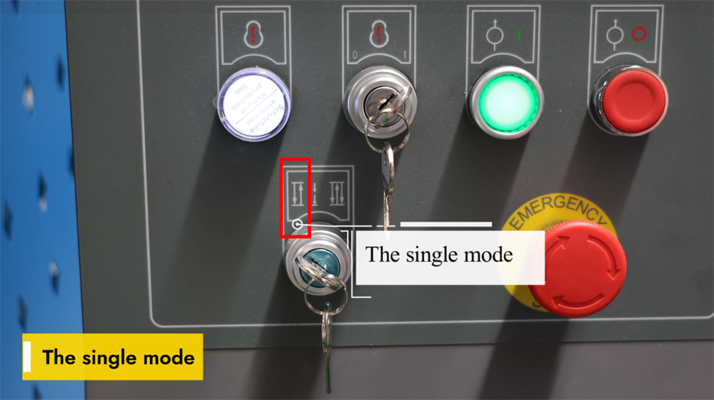
○ Single Mode on the E21 System
○ Jog Mode on the E21 System
○ Continuous Mode on the E21 System
5. Step 4: System Operation and Control
○ Programming Instructions for the E21 NC Press Brake
○ Setting YP=93 and XP=50 for Bending Operations
○ Calibrating a 93-Degree Bend to the Target Angle
○ Adjusting the Accuracy of Bending Length
6. Step 5: System Calibration Process
○ Y-Axis Calibration for the E21 Press Brake
○ Fine-Tuning YP for Precision Bending
○ X-Axis Calibration Instructions
○ Double-Click "P" to Enter Setup Mode
○ Enter Password 1212 on the CONST Interface
○ Selecting the Appropriate X-Tea on the TEACH Page
○ Inputting the Exact Required Bending Length
○ Double-Click "P" to Resume Bending Operations
7. Step 6: Practical Production Demonstration
○ Achieving a 90-Degree Bending Angle
○ Understanding Bending Length on the E21 System
8. Step 7: Correct Shutdown Procedure
○ Operating the Pump Stop Switch
○ Engaging the E-Stop for Safety Purposes
○ Properly Powering Off the E21 NC Press Brake
9. Conclusion
Mastering the operation of the E21 NC press brake system can be a challenging task for many operators. This comprehensive operation manual is designed to guide you through every step of operating and optimizing this equipment with ease. It covers all the essential procedures for setup, daily operation, and basic maintenance of the E21 NC press brake, equipping you with the knowledge to boost the machine’s operational efficiency to the maximum. Now, let’s dive into the detailed step-by-step setup and operation guidelines for this system.
Overview of the E21 System Operation Manual
In modern metal fabrication, the press brake is an indispensable piece of equipment for sheet metal bending processes. This manual provides a detailed step-by-step operation tutorial for NC press brakes equipped with the E21 control system. Whether you are a novice operator new to press brakes or a seasoned professional in need of a refresher, this guide will help you master the setup, operation, and calibration of the E21 NC press brake, ensuring the equipment delivers optimal performance in production.
Step 1: Hydraulic Oil Filling and Electrical Wiring Connection
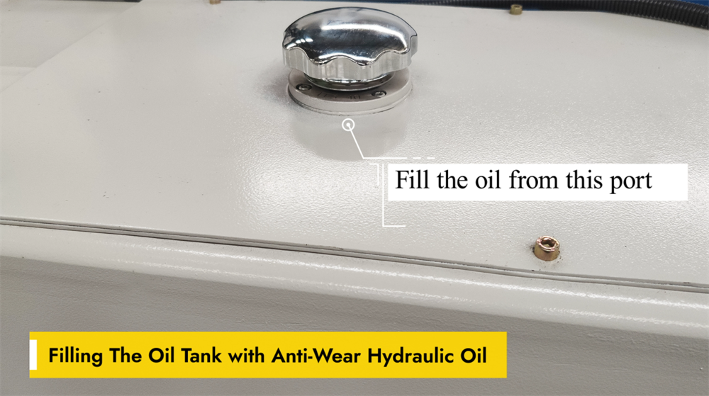
Correct Filling of the Hydraulic Oil Tank
Smooth operation of the E21 NC press brake hinges on the proper filling of its hydraulic oil tank with anti-wear hydraulic oil. This specialized oil reduces friction between hydraulic components and prevents premature wear, thereby enhancing the machine’s overall performance. When refueling, use the dedicated oil filling port on the machine and ensure the oil level stays within the manufacturer’s recommended range. Overfilling the tank or using low-quality hydraulic oil can lead to system inefficiencies and even permanent damage to components. Regularly check the oil level and replace the hydraulic oil as required to maintain the press brake’s optimal working condition.
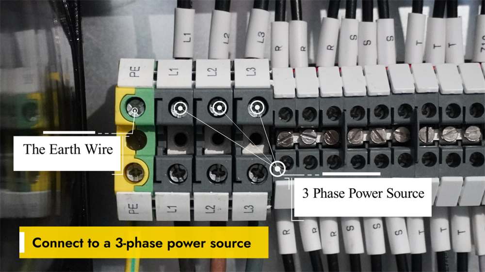
Power Connection for the NC Press Brake
Prior to operating the NC press brake, it is critical to connect the machine to a stable three-phase power supply, which is essential for ensuring stable performance and preventing electrical malfunctions. Verify that the voltage of the power supply matches the machine’s specified electrical parameters. All wiring work must be completed by a qualified electrician, who will ensure secure connections and full compliance with electrical safety regulations. After the wiring is done, check the machine’s grounding to eliminate electrical safety hazards. Turn on the main power switch and inspect the control panel for any error codes or warning messages. If the panel displays no abnormalities, the system is ready for operation. Always adhere to the manufacturer’s guidelines for the safe and efficient use of the equipment.
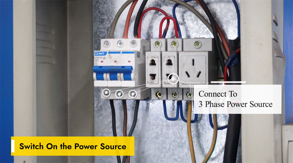
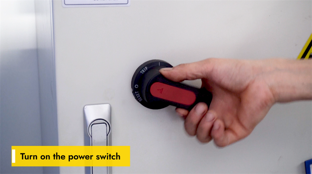
Activating the Main Power Supply
Before starting the E21 NC press brake, confirm that the machine is connected to a stable power supply and that the voltage meets the equipment’s requirements to avoid electrical faults. Locate the main power switch, typically mounted on the side or rear of the machine, and switch it to the "ON" position. Wait a few seconds for the system to complete its initialization process; the control panel should display startup information, indicating that the system is ready for use. If any error codes appear on the panel, refer to the official operation manual for troubleshooting solutions. Strictly follow all safety protocols before initiating any sheet metal bending operations.
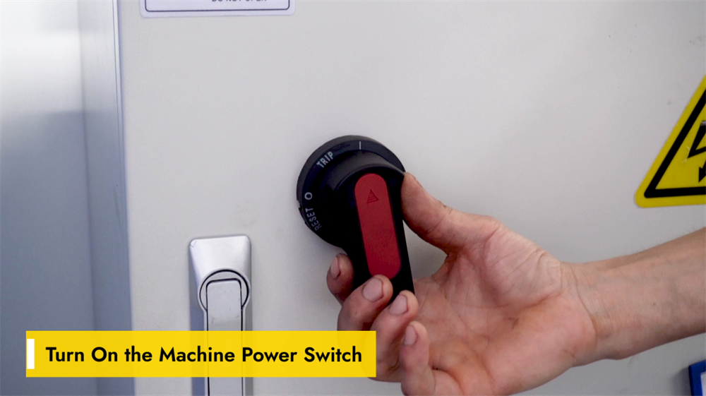
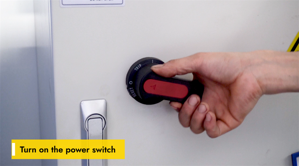
Turning On the Machine’s Power Switch
Ensure the power supply is stable and meets the specified voltage requirements before operating the E21 NC press brake. Locate the main power switch on the machine’s control panel or electrical cabinet and switch it to the "ON" position, then wait for the system to initialize. Check if the controller screen lights up and loads the startup interface, and listen for any unusual noises from the machine, which may signal underlying electrical issues. If the system fails to start normally, inspect the power supply and the emergency stop button for malfunctions. Always follow safety protocols and wear appropriate personal protective equipment before operating the machine.
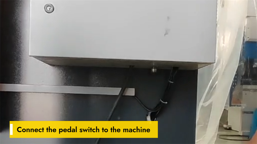
Connecting the Foot Pedal Switch
A secure connection of the foot pedal switch is essential for the proper operation of the E21 NC press brake. First, find the dedicated pedal connection port on the machine’s control panel or base unit. Align the pedal switch connector with the port and insert it firmly until a click is heard, ensuring a tight connection to prevent accidental disconnection during operation. Once the connection is complete, test the pedal’s responsiveness by pressing it lightly. If the machine does not react to the pedal input, check for loose wiring or power supply issues. A properly connected foot pedal not only improves operational control but also enhances workplace safety during bending processes.
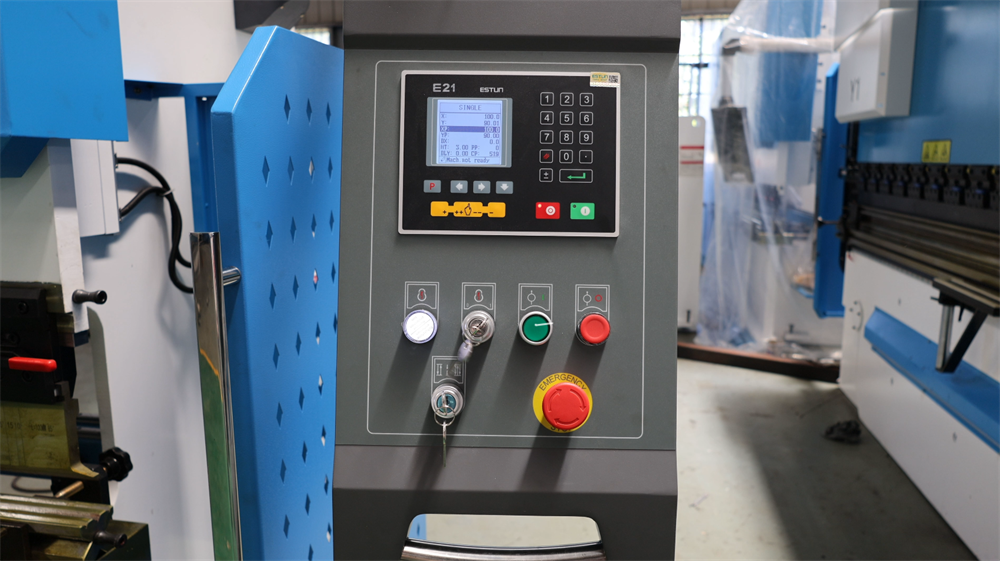
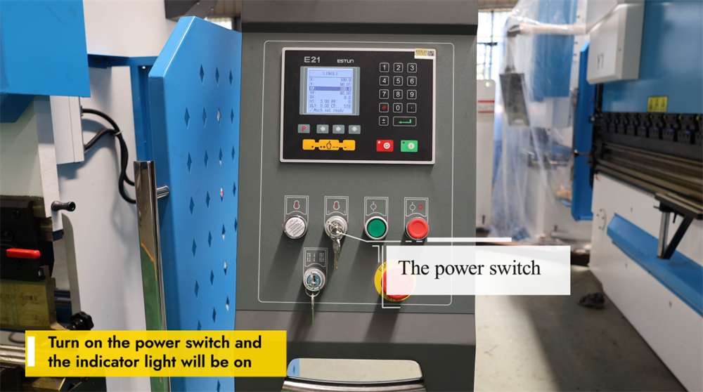
Powering Up the E21 Press Brake
To start operating the E21 NC press brake, first locate the main power switch on the machine’s control panel and confirm that the equipment is connected to a stable power supply. Switch the power to the "ON" position; the indicator lights or the control display screen will activate, confirming that the machine has been powered on successfully. Allow the system a few seconds to finish initializing before performing any further operations. If the machine fails to power on, inspect the power supply, emergency stop button, and circuit breakers to identify and resolve any functional issues. Always follow safety guidelines when handling the machine’s electrical components.
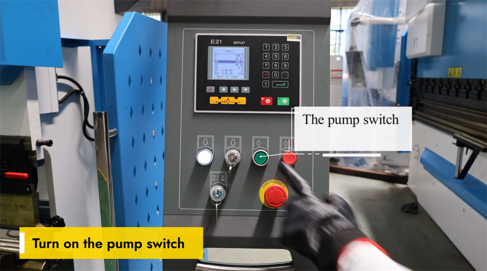
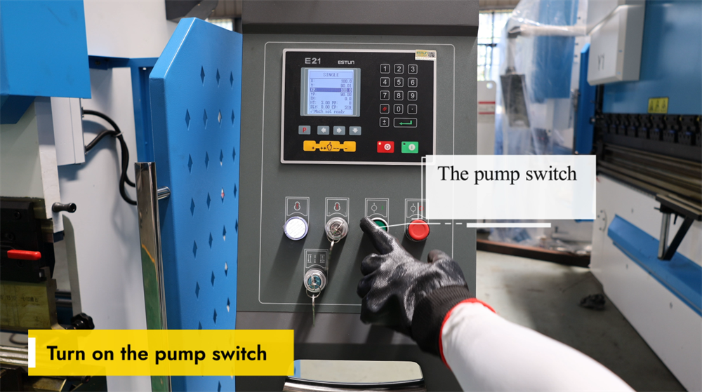
Correct Activation of the Pump Switch
Before operating the E21 NC press brake, confirm that the machine is properly connected to the power supply. Locate the pump switch on the control panel and turn it on to activate the hydraulic system. A steady hum should be heard, indicating that the hydraulic pump is running smoothly. At this stage, check the hydraulic oil level and inspect the system for any oil leaks or abnormal noises. If the hydraulic system fails to start, examine the power connections and the emergency stop button for faults. A properly activated hydraulic pump ensures stable hydraulic pressure and smooth bending operations, preventing errors in the sheet metal bending process. Always follow safety guidelines when operating the machine.

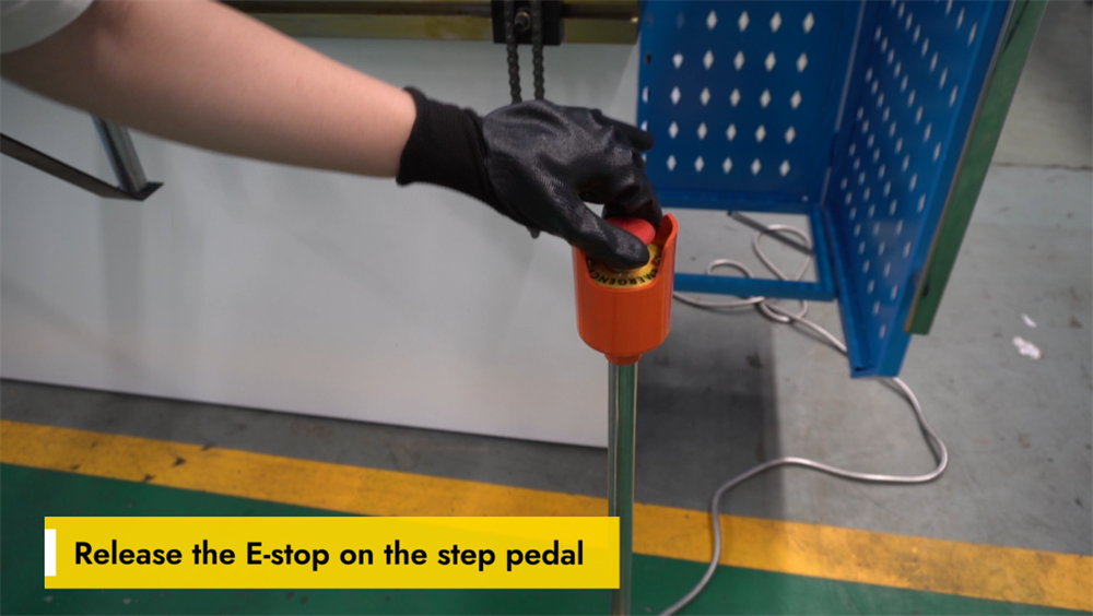
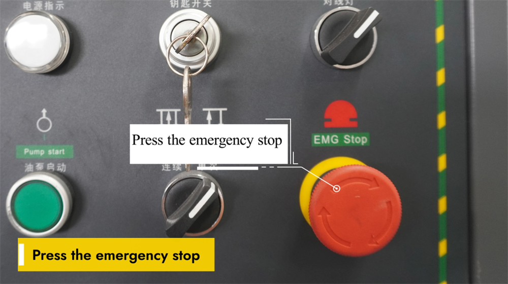
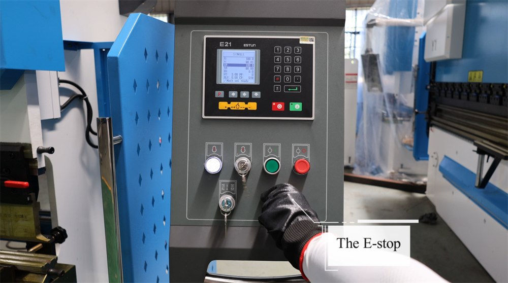
Releasing the Emergency Stop on the Foot Pedal
To restore normal operation of the E21 NC press brake, the emergency stop (E-stop) button on the foot pedal must first be released. The E-stop is a critical safety feature that immediately halts all machine functions to prevent workplace accidents. To release the E-stop, press the button firmly and twist it counterclockwise (the operation may vary slightly by machine model) until it pops back to its original position. After releasing the E-stop, check the control panel to confirm that the system has been reset successfully. Always ensure the foot pedal is placed on a stable surface before resuming machine operation. Proper handling of the E-stop feature is key to maintaining workplace safety and ensuring smooth bending operations.
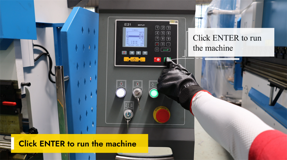
Pressing the ENTER Key to Start the Machine
Pressing the ENTER key is the final step to initiate the E21 NC press brake and start the sheet metal bending process. After correctly setting all bending parameters—including the bending angle, material thickness, and backgauge position—simply press the ENTER key to confirm and execute the programmed operation. The system will then control the ram to perform precise bending according to the preset parameters. Before pressing the ENTER key, always ensure the workpiece is positioned correctly and that all safety precautions are in place. This simple yet critical step ensures efficient and accurate metal bending, optimizing both productivity and product quality in sheet metal fabrication.
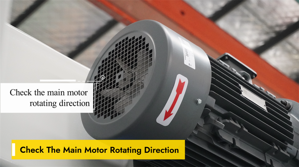
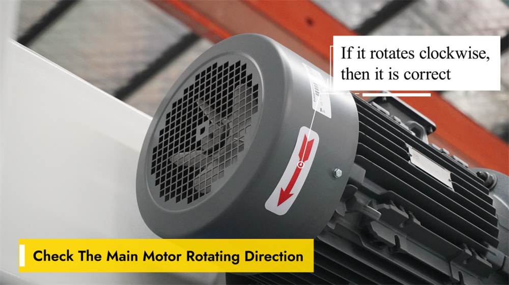
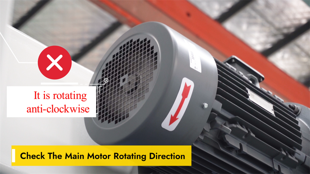
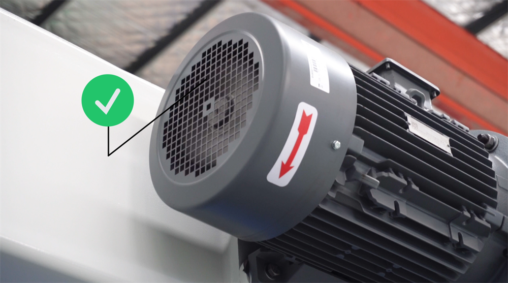
Verifying the Rotation Direction of the Main Motor
Verifying the rotation direction of the main motor is a crucial pre-operation step for the E21 NC press brake, as incorrect rotation can lead to operational inefficiencies and even damage to the system. To check the rotation direction, power on the machine and observe the motor’s movement. If the motor is rotating in the wrong direction, swap any two power lines to adjust the phase sequence and correct the rotation. Always confirm that the motor runs smoothly and in the correct direction before proceeding with any bending operations. Regular inspection of the motor’s rotation direction prevents unnecessary wear on components and ensures consistent bending accuracy and long machine service life.
Clockwise Rotation = Normal Operation
When operating the E21 NC press brake system, it is essential to ensure the adjustment knob and main motor rotate in the correct direction. A clockwise rotation generally indicates that the machine’s moving parts are functioning properly, which is critical for precise positioning and consistent bending accuracy. A counterclockwise rotation may signal an incorrect system setting, which could lead to errors in bending angles or component misalignment. Always verify the rotation direction before starting any bending operations to avoid production issues. Proper machine setup and calibration not only maintain operational efficiency but also extend tool life and improve overall production quality in metal fabrication.
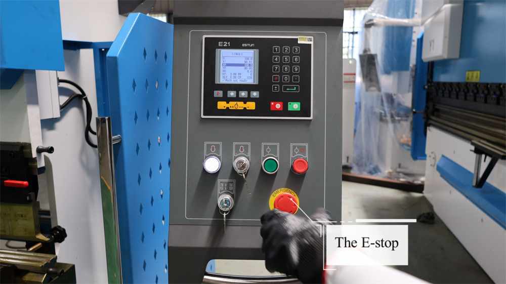
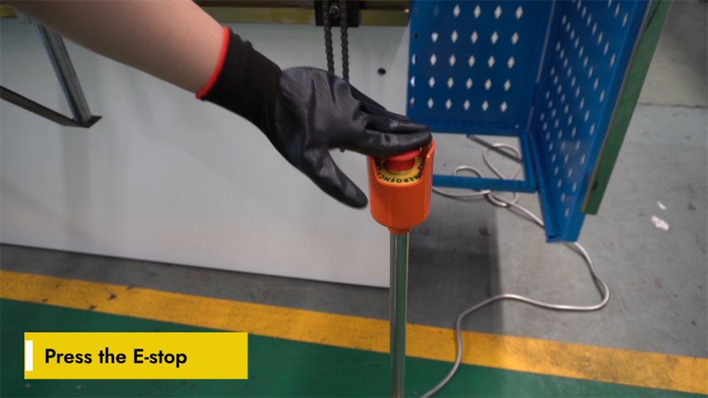
Emergency Stop Operation
In the event of equipment malfunctions or potential safety hazards during the operation of the E21 NC press brake, press the emergency stop button immediately. This action will cut off the machine’s power supply instantaneously, halting all movement and ensuring the operator’s safety. Before starting any bending operation, always ensure the emergency stop button is easily accessible and unobstructed. Regularly inspect the button to confirm it is functional and free from debris. After activating the emergency stop, identify and resolve the underlying issue completely before restarting the machine. Proper use of this safety feature minimizes workplace risks and enhances overall operational safety.
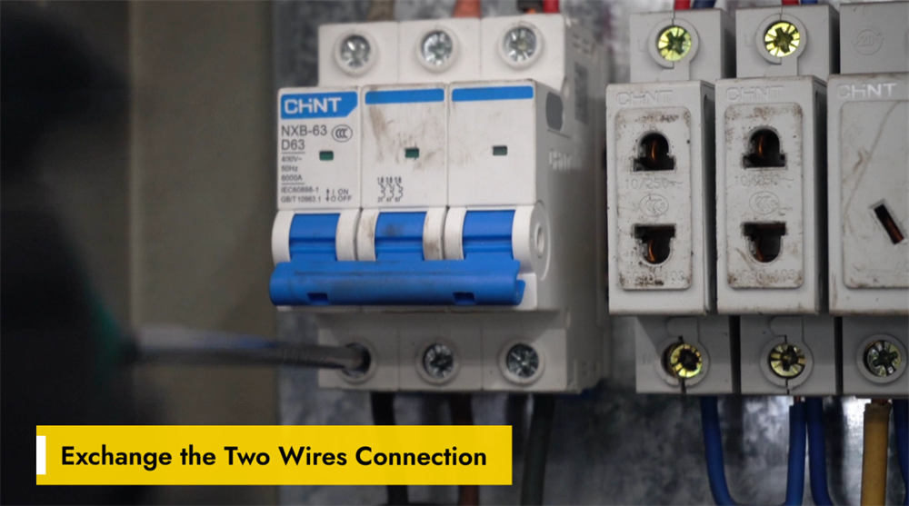
Correcting Wiring by Swapping Two Wires
Incorrect wiring can cause malfunctions in the movement direction of the E21 NC press brake’s backgauge or ram, or lead to abnormal system responses. If the backgauge or ram moves in the wrong direction, a simple solution is to swap the two wire connections on the motor or control panel. This adjustment reverses the motor’s phase sequence, restoring normal operation. Before making any wiring changes, turn off the machine’s power supply and refer to the wiring diagram to avoid electrical safety hazards. After swapping the wires, restart the machine and test the movement of the backgauge and ram to confirm correct operation. This quick troubleshooting method helps maintain operational efficiency and minimize unplanned downtime.
Step 2: Machine Startup Procedure
Powering Up the E21 NC Press Brake
Before operating the E21 NC press brake, confirm the machine is connected to a stable power supply. Locate the main power switch on the electrical panel (usually on the side or rear of the machine) and switch it to the "ON" position, then wait for the system to initialize. The control panel will display startup information when the system is ready for use; check the panel for any error messages or warning prompts. If the panel shows no abnormalities, proceed to set the required bending parameters. Always follow electrical safety guidelines when handling the machine’s electrical components to prevent accidents.
Proper Startup of the Hydraulic Oil Pump
Starting the hydraulic oil pump is the first step to operating the E21 NC press brake. Ensure the power supply is stable and the machine is properly connected, then press the oil pump start button on the control panel to activate the hydraulic system. A steady hum will indicate that the pump is running smoothly; listen for any unusual noises or vibrations during operation. Allow the pump to circulate hydraulic oil evenly throughout the system before performing any bending operations. Proper startup of the oil pump ensures stable hydraulic pressure, smooth bending performance, and long-term reliability of the machine.
Releasing the Emergency Stop Switch
Before operating the E21 NC press brake, confirm that the emergency stop switch is released properly. This switch is a core safety feature that immediately halts all machine operations in case of an emergency. To release the switch, turn it clockwise until it pops out, indicating that the system has been reactivated. After releasing the switch, check the control panel for any error messages and reset the system if necessary. Always verify that the machine is in a safe and ready state before starting any operations. Proper handling of the emergency stop switch ensures workplace safety and minimizes unplanned downtime.
Releasing the E-Stop on the Foot Pedal
To resume operation of the E21 NC press brake, the emergency stop (E-stop) button on the foot pedal must be released. First, check if the E-stop button is engaged; if so, turn it clockwise to reset it. Next, ensure the foot pedal is in the correct position and free from any obstructions, then press the pedal lightly to confirm the system responds correctly. If the machine fails to start, check all safety interlocks and reset the controller if needed. Proper release of the E-stop ensures smooth machine operation and reduces downtime during sheet metal bending processes.
Initiating Press Brake Operation via the ENTER Key
Pressing the ENTER key activates the E21 NC press brake and initiates the pre-programmed bending sequence. Before pressing the ENTER key, confirm that all parameters—including the bending angle, backgauge position, and hydraulic pressure settings—are programmed correctly. Once confirmed, pressing the ENTER key signals the machine to execute the bending operation. Operators should monitor the entire process to ensure smooth operation and maintain bending precision. Critical safety measures, such as keeping hands clear of moving parts and wearing personal protective equipment, must be followed at all times. Proper use of the ENTER key improves operational efficiency, reduces production errors, and ensures consistent bending accuracy in metal fabrication.
Step 3: Explanation of Operational Modes
Single Mode on the E21 System
The Single Mode of the E21 NC press brake allows operators to manually execute individual bending steps one at a time. This mode is ideal for small-batch production and custom bending tasks, as it provides maximum flexibility and precise control over each individual operation. Operators can set the bending angle, backgauge position, and ram stroke limits for each step before executing it independently. The system ensures accurate performance while allowing real-time parameter adjustments during operation. Single Mode is particularly valuable for prototype development and one-off custom projects, as it delivers high bending precision without the need for complex programming. Mastering this mode can significantly improve operational efficiency and minimize errors in sheet metal bending processes.
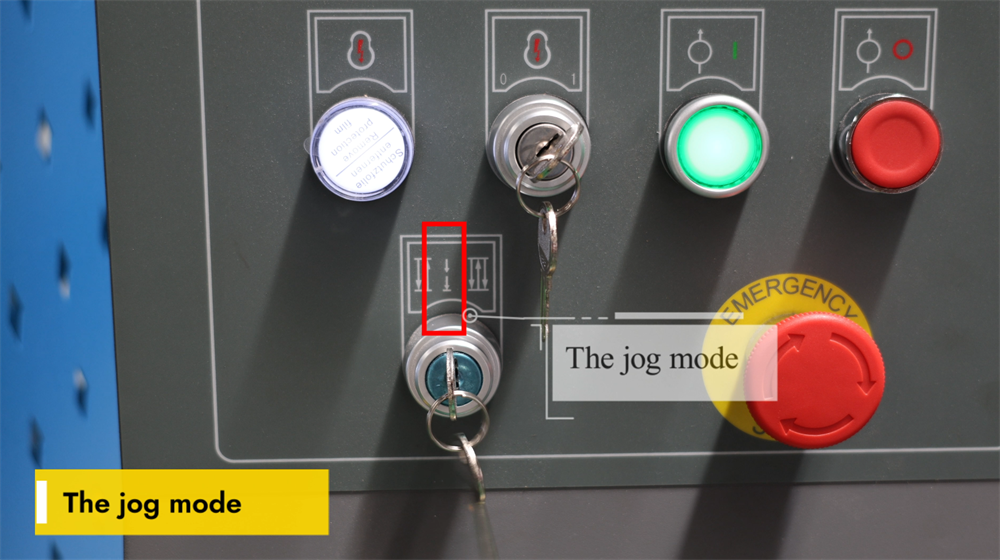
Jog Mode on the E21 System
The Jog Mode of the E21 NC press brake enables operators to manually control the ram’s movement for precise positioning. This mode is primarily used for tooling setup, testing bending angles, and ensuring positioning accuracy before full-scale production. By pressing the jog button, the ram moves incrementally, giving operators complete control over bending depth and component alignment. Jog Mode is especially useful for fine-tuning parameters, reducing production errors, and improving work efficiency. Operators should use this mode with caution to avoid over-adjustment of the ram position. Mastering the Jog Mode function enhances machine accuracy and ensures consistent bending results, making it an essential feature for machine setup and calibration.
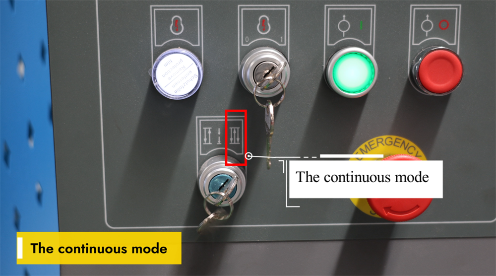
Continuous Mode on the E21 System
The Continuous Mode of the E21 NC press brake enables uninterrupted bending operations, significantly boosting efficiency in mass production scenarios. When activated, the machine automatically cycles through the pre-programmed bending sequence without requiring the operator to restart the process for each workpiece. This mode is ideal for high-volume sheet metal fabrication, as it reduces unplanned downtime and improves overall productivity. Before enabling Continuous Mode, operators must ensure proper tool alignment and workpiece positioning to maintain bending accuracy and consistency. Regular monitoring of the machine during operation is also essential to prevent component misalignment or production errors. Effective use of Continuous Mode allows manufacturers to achieve faster production cycles and consistent bending quality, optimizing the overall operational performance of the press brake.
Step 4: System Operation and Control
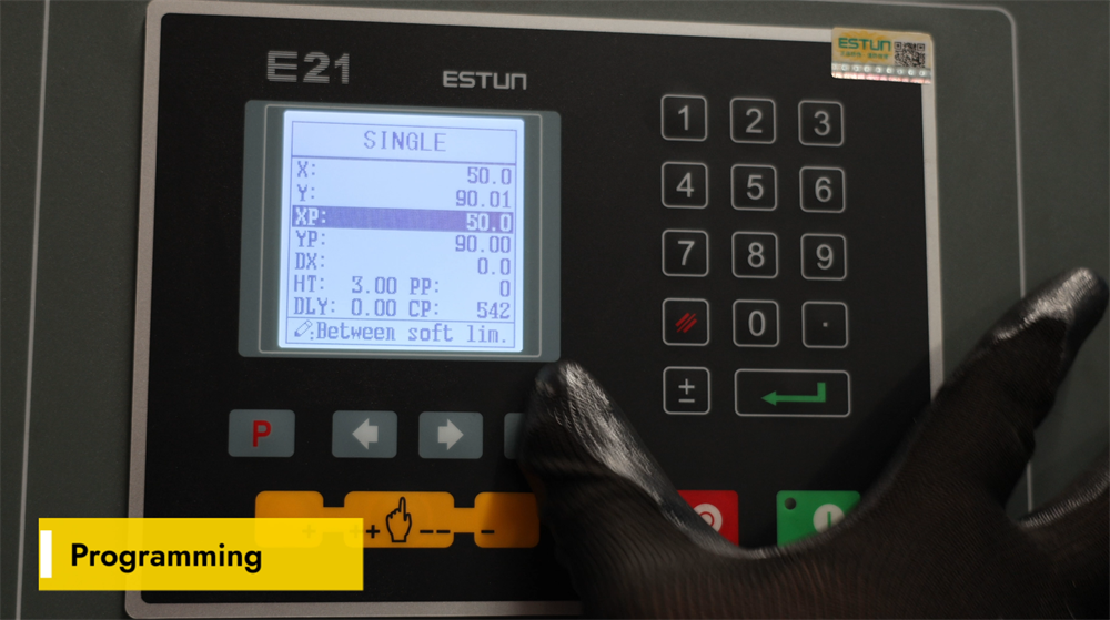
Programming Instructions for the E21 NC Press Brake
The E21 NC press brake features a simple yet powerful programming interface designed for efficient sheet metal bending. Operators can set bending angles, backgauge positions, and multi-step bending sequences via the digital control panel. The system supports multi-step programming, allowing operators to store multiple bending procedures for complex fabrication projects. To optimize the machine’s performance, ensure accurate input of material parameters, proper tool selection, and regular system calibration. The E21 controller offers a user-friendly operating experience, making it an ideal choice for small to medium-scale metal fabrication workshops. Mastering the programming of the E21 NC press brake can significantly increase production productivity and bending precision, while reducing production errors and material waste.
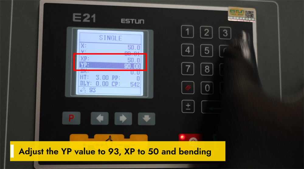
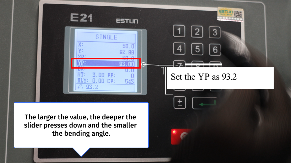
Setting YP=93 and XP=50 for Bending Operations
Achieving precise bending results with the E21 NC press brake requires the correct adjustment of YP and XP parameters. Set the YP value to 93 to ensure accurate positioning of the ram, which directly impacts bending depth and consistency. Adjust the XP value to 50 to optimize the backgauge position for precise workpiece alignment. Proper calibration of these two parameters significantly enhances bending accuracy, reduces material waste, and improves overall operational efficiency. Regular inspection and fine-tuning of these settings can further boost the machine’s performance, ensuring high-quality bends with minimal errors in sheet metal fabrication.
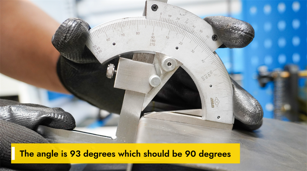
Calibrating a 93-Degree Bend to the Target Angle
If the actual bending angle is 93 degrees instead of the target 90 degrees, parameter adjustments are required to improve accuracy. This deviation is often caused by material springback, incorrect selection of punches and dies, or insufficient hydraulic pressure settings. To correct the angle, operators can increase the machine’s tonnage, use a V-die with a tighter opening, or apply over-bending techniques to compensate for material springback. Additionally, checking the backgauge positioning and performing a full press brake calibration can help achieve the precise 90-degree target angle. Regular inspection of material thickness and bending parameters ensures consistent production results and minimizes errors. Proper parameter adjustments not only enhance bending accuracy but also improve the overall operational efficiency of the machine.
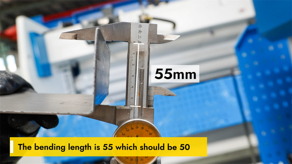
Adjusting the Accuracy of Bending Length
If the actual bending length is 55 mm while the desired length is 50 mm, adjustments are needed to achieve precise bending. First, check the settings on the E21 NC controller and confirm that the backgauge position is calibrated correctly. Adjust the bending parameters in the control system and verify the alignment of punches and dies to minimize dimensional deviations. If necessary, fine-tune the workpiece positioning and perform test bends to confirm the accuracy of the bending length. Regular maintenance of the backgauge and hydraulic system also helps maintain consistent bending results. Proper adjustment of the bending length ensures precision in production, reduces material waste, and improves overall production efficiency.
Step 5: System Calibration Process
Y-Axis Calibration for the E21 Press Brake
Y-axis calibration of the E21 NC press brake is essential for ensuring accurate bending depth and consistent results in metal fabrication. Proper calibration aligns the ram’s movement with the pre-programmed bending parameters, preventing dimensional deviations and material waste. To calibrate the Y-axis, access the E21 controller, navigate to the Y-axis settings interface, and input the correct reference values based on the installed tooling and the thickness of the workpiece material. Perform test bends after inputting the values and measure the results to fine-tune the settings as needed. Regular Y-axis calibration maintains bending precision and extends the service life of tools, ensuring high-quality bends in all operations. Always follow the manufacturer’s guidelines during calibration to achieve optimal machine performance and prevent component misalignment.
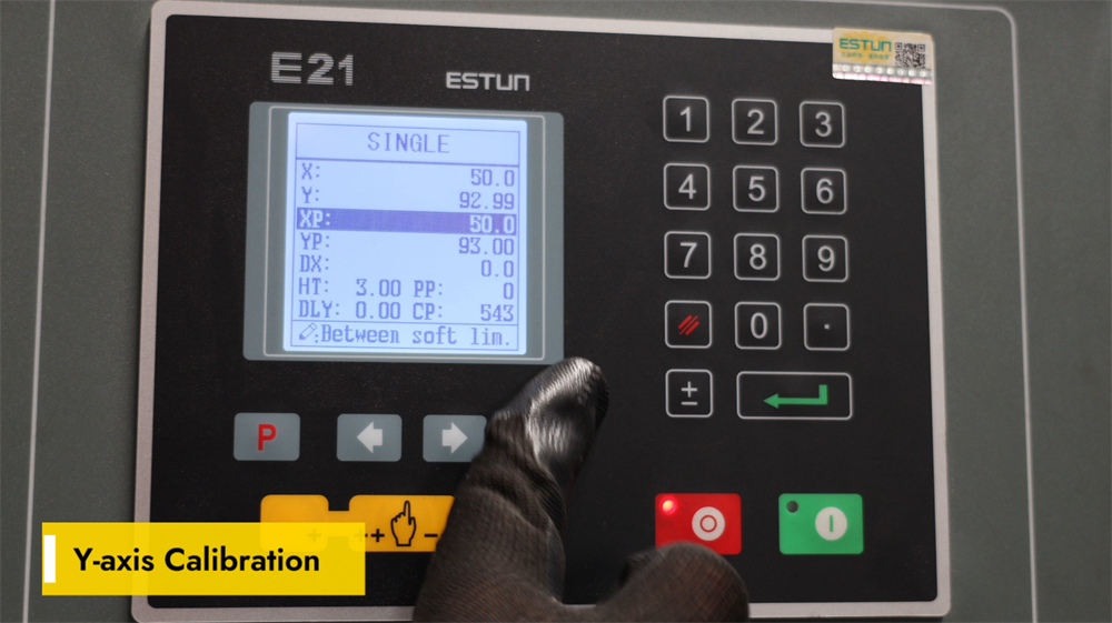
Fine-Tuning YP for Precision Bending
Setting the YP value to 93.2 determines the downward stroke depth of the slider during the bending process. A higher YP value allows the slider to press deeper into the workpiece, resulting in a smaller bending angle. Conversely, a lower YP value limits the slider’s downward movement, producing a larger bending angle. Proper adjustment of the YP value ensures accurate and consistent bending results, minimizing material waste and enhancing operational efficiency. Operators should fine-tune the YP setting based on the thickness of the workpiece material and the desired bending angle to achieve optimal precision. Regular calibration of the YP value is essential for maintaining high-quality bends in sheet metal fabrication.
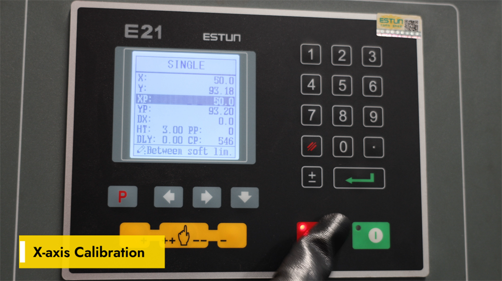
X-Axis Calibration Instructions
Proper X-axis calibration is critical for ensuring accurate backgauge positioning on the E21 NC press brake, which is a key factor in precise sheet metal bending. To calibrate the X-axis, access the parameter settings interface on the E21 controller and input the actual physical position of the backgauge. Use a high-precision measuring tool to verify the distance between the backgauge and the designated bending line, then adjust the parameters and save the settings if needed. Regular X-axis calibration prevents dimensional errors in workpieces and enhances the consistency of bending results. Always recheck the X-axis calibration after changing tooling or performing machine maintenance. A well-calibrated X-axis improves operational efficiency, reduces rework, and ensures high-precision metal bending operations.
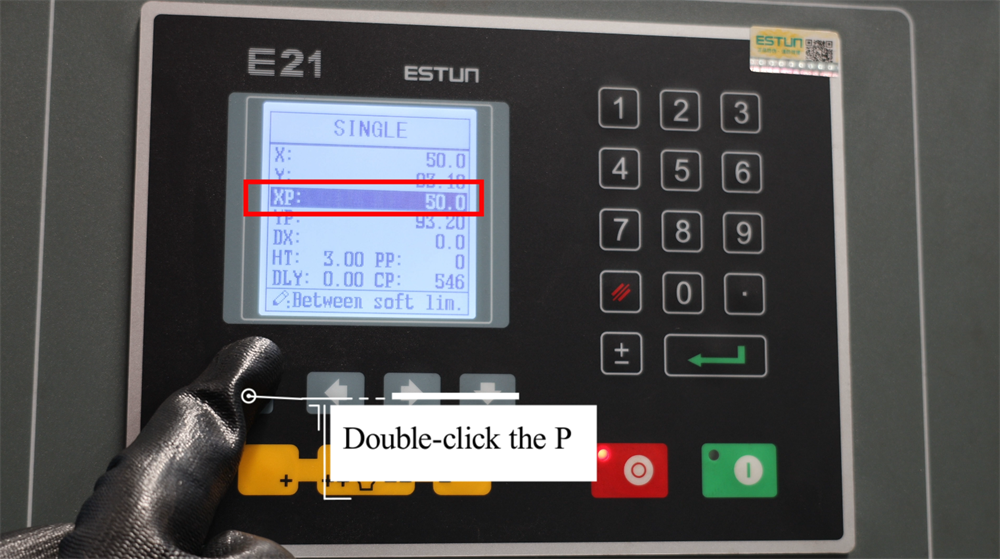
Double-Click "P" to Enter Setup Mode
Double-clicking the "P" key is a critical step to enter the programming and setup mode of the E21 NC press brake. This action allows operators to efficiently set bending angles, backgauge positions, and ram stroke parameters for upcoming operations. Once in setup mode, operators can input numerical values for all required parameters and confirm the settings to ensure precise bending operations. This function streamlines the workflow, reducing machine setup time and minimizing production errors. Always confirm that all parameters are entered correctly before starting the bending process to achieve optimal production results. Mastering this simple step simplifies the operation of the E21 NC controller and ensures more accurate and efficient metal bending.
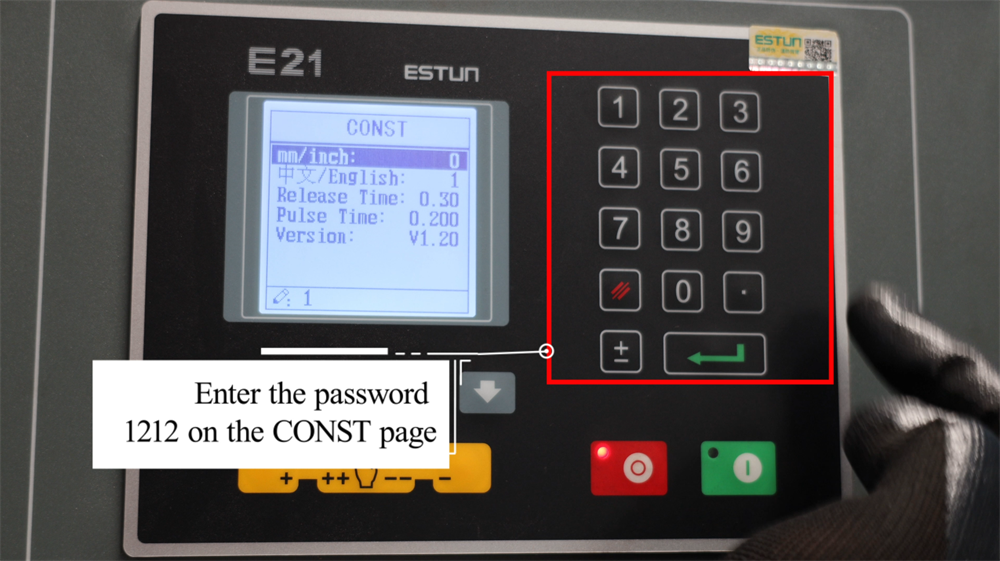
Enter Password 1212 on the CONST Interface
To access the advanced setting options of the E21 NC press brake, navigate to the CONST interface on the controller’s display. When prompted for a password, enter 1212 to unlock the restricted configuration parameters. This access allows operators to adjust core system parameters, optimize bending precision, and modify operational settings to match specific production requirements. Accurate input of the password is critical to avoid access restrictions. Once the advanced settings are unlocked, carefully review and configure the parameters according to the specific sheet metal bending needs of your production line. If you are unsure about any adjustments, refer to the official operation manual or contact the technical support team at JUGAO for assistance.
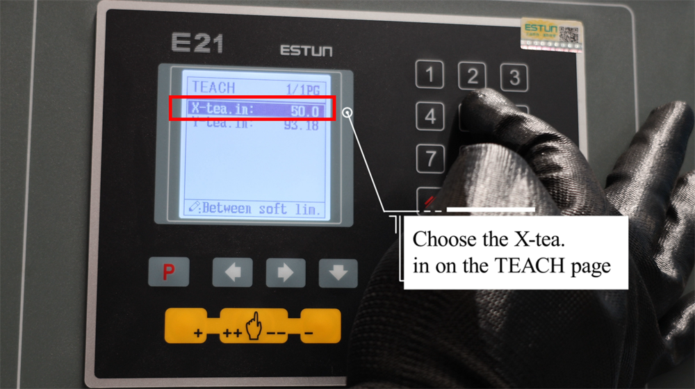
Selecting the Appropriate X-Tea on the TEACH Page
On the TEACH page of the E21 controller, selecting the appropriate X-Tea option ensures you receive a tailored learning experience that matches your operational needs. Each X-Tea option is designed to provide comprehensive insights into different aspects of the E21 system, making it easier for operators to master key operational concepts. Whether you are a beginner looking for a basic operation guide or a seasoned professional in need of advanced technical details, the TEACH page offers structured learning options to suit all levels. Simply browse the available X-Tea selections, compare their content and features, and choose the one that best aligns with your learning goals. With clear instructions and well-organized content, the X-Tea options allow you to quickly grasp essential operational knowledge and apply it effectively in real-world production scenarios.
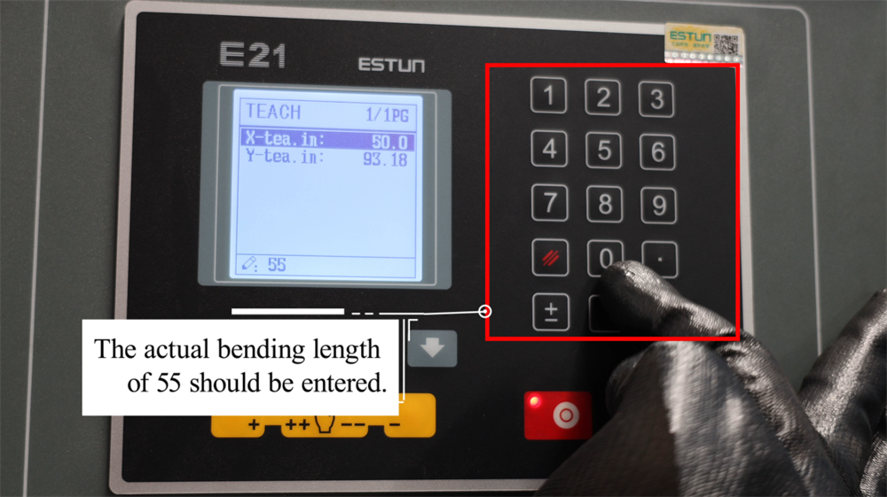
Inputting the Exact Required Bending Length
Accurate input of the actual required bending length is a key setup step for the E21 NC press brake, as it directly ensures precise bending results. If the production requirement is a 55mm bending length, input the value 55 into the control system. This ensures that the backgauge position and all related bending parameters are aligned with the workpiece’s dimensional requirements, preventing errors in the final bent product. Accurate parameter input minimizes material waste and boosts production productivity. Always verify the entered values before starting the bending operation to avoid workpiece misalignment. Proper data entry into the E21 system is critical for achieving consistent bending accuracy and optimizing the overall efficiency of the press brake.
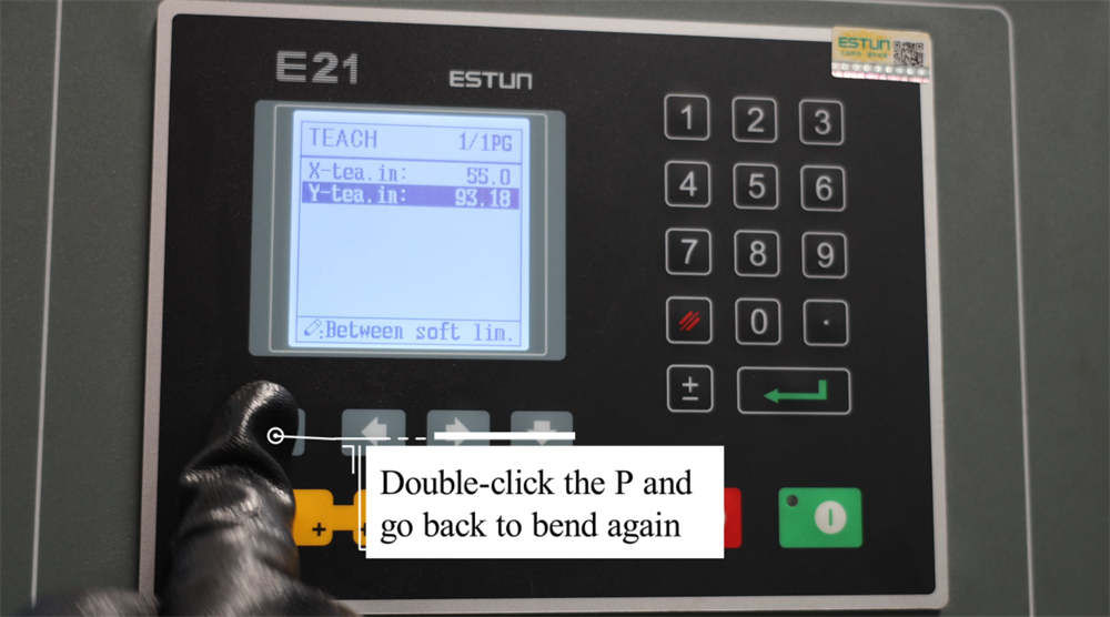
Double-Click "P" to Resume Bending Operations
During the operation of the E21 NC press brake, operators can quickly resume the bending process by double-clicking the "P" button on the controller. This function is particularly useful when you need to reposition the workpiece or fine-tune parameters before continuing the pre-programmed bending sequence. After double-clicking the "P" button, the machine will automatically return to the last bending position, enabling a smooth and efficient production workflow. This feature helps improve operational speed and bending accuracy, reducing downtime between individual bending steps. Mastering this function ensures higher productivity and precision in sheet metal forming processes. Always recheck the workpiece and ram positioning before resuming operation to avoid misalignment and production errors.
Step 6: Practical Production Demonstration
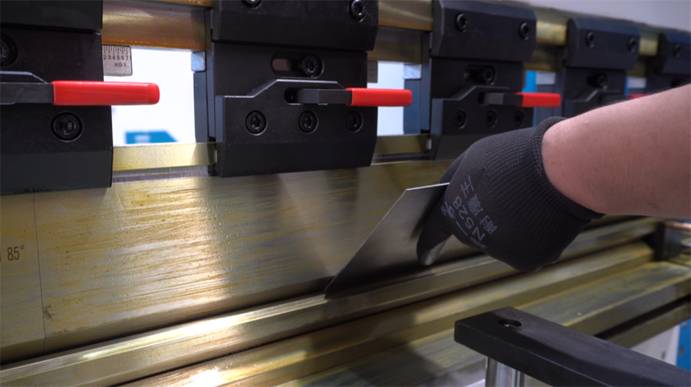
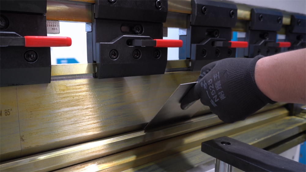
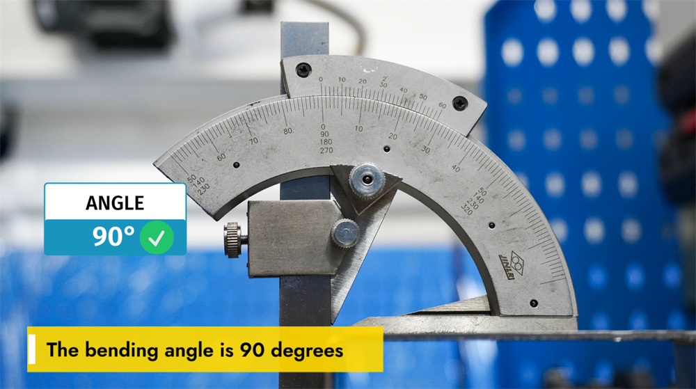
Achieving a 90-Degree Bending Angle
A 90-degree bending angle is one of the most common requirements in metal fabrication, and achieving this angle consistently and precisely depends on several key factors, including workpiece material thickness, die selection, and press brake parameter settings. The correct V-die width and punch radius play a pivotal role in maintaining bending accuracy. Additionally, adjusting the bending force and backgauge position ensures the repeatability of 90-degree bends across multiple workpieces. Operators must also account for material springback and apply appropriate compensation techniques to prevent angular deviations. Using an NC-controlled press brake like the E21 system helps maintain consistent bending results across high-volume production, reducing errors and improving operational efficiency. Proper system calibration and tool selection are the foundation for achieving a perfect 90-degree bend every time.
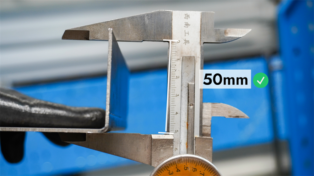
Understanding Bending Length on the E21 System
The bending length of the E21 NC press brake refers to the maximum length of sheet metal that can be bent in a single operation, which is determined by the machine’s working table size and the installed tooling configuration. Properly setting the bending length according to production requirements ensures accurate bending results, minimizes material waste, and prevents overloading of the tooling. Operators should always refer to the machine’s technical specifications, select appropriate punches and dies, and adjust the backgauge position to match the required bending length for precise results. A clear understanding of the machine’s bending length capabilities is essential for optimizing production productivity and achieving consistent bending accuracy in sheet metal fabrication.
Step 7: Correct Shutdown Procedure
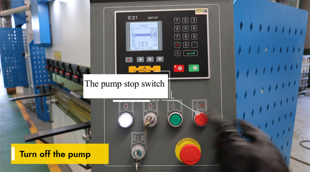
Operating the Pump Stop Switch
The pump stop switch is a key component of the E21 NC press brake system, allowing operators to safely shut down the hydraulic pump when the machine is not in use. Pressing this switch stops the hydraulic pump immediately, preventing unnecessary energy consumption and reducing wear on the hydraulic system’s components. It is essential to turn off the hydraulic pump after all bending operations are completed to extend the machine’s service life and ensure workplace safety. Before restarting the pump for subsequent operations, check that the switch is properly engaged to avoid system malfunctions. Regular maintenance and adherence to proper shutdown procedures help maintain the press brake’s optimal performance over time.
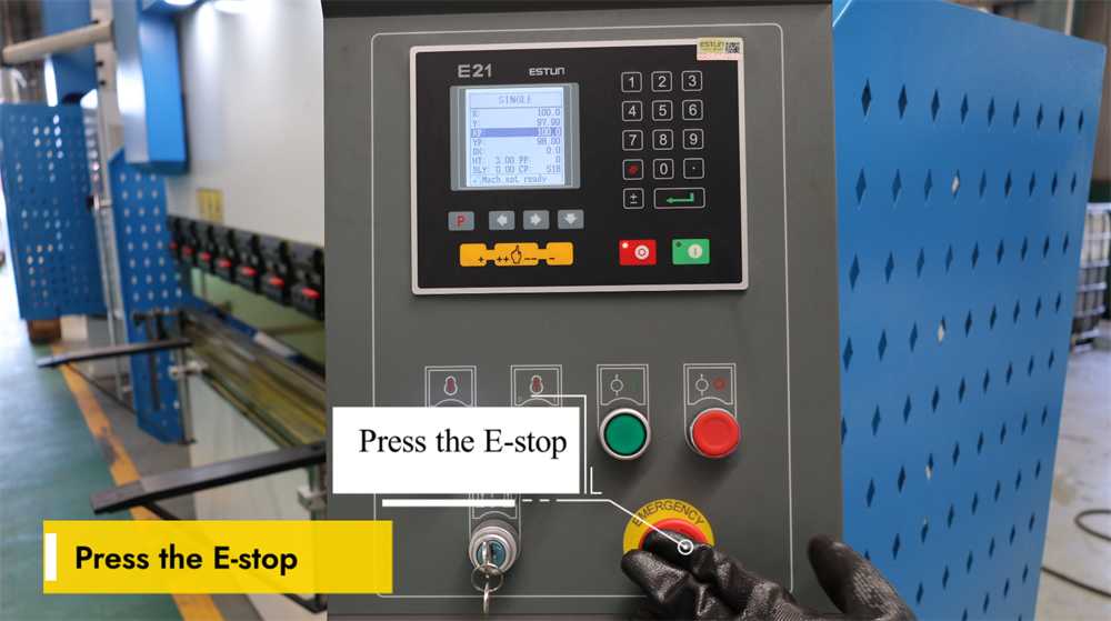
Engaging the E-Stop for Safety Purposes
The emergency stop (E-stop) button is a critical safety feature on the E21 NC press brake. Pressing this button immediately halts all machine operations, effectively preventing potential workplace hazards in emergency situations. Operators should activate the E-stop in the event of sudden equipment malfunctions, unexpected workpiece movement, or any other potential safety risks. After the E-stop is activated, the machine must be fully reset and the underlying issue resolved before operation can resume. Regularly inspect the E-stop button to confirm it is functional and free from obstructions. Proper use of this safety feature enhances workplace safety and protects both the operator and the equipment from damage. Always follow the official safety guidelines when operating the E21 NC press brake.
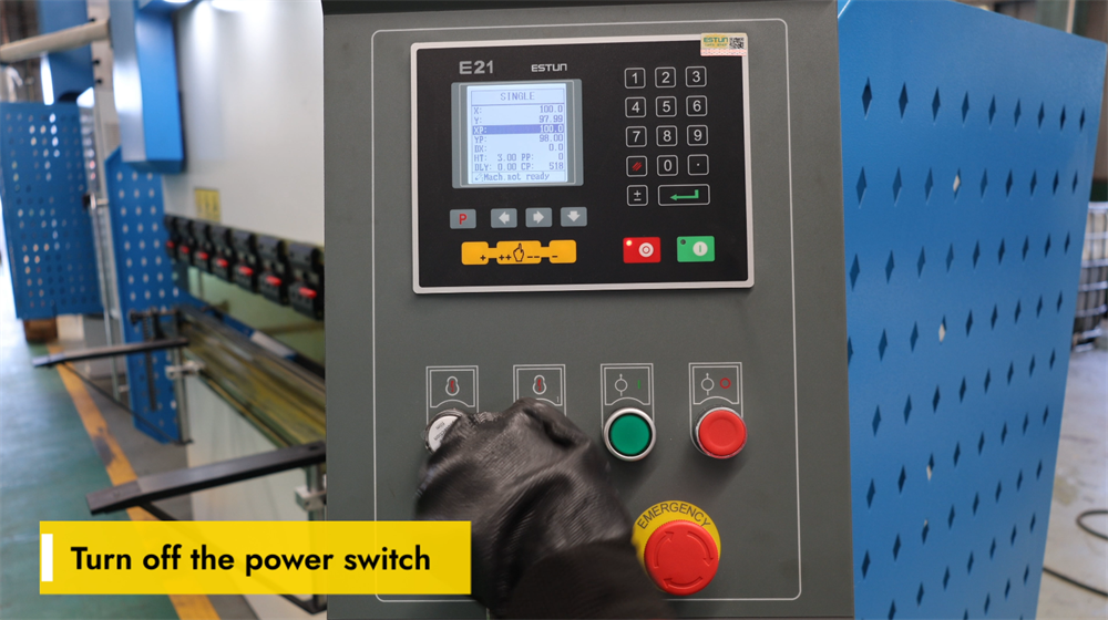
Properly Powering Off the E21 NC Press Brake
Before performing any maintenance work or completing daily production by shutting down the E21 NC press brake, it is critical to turn off the main power switch correctly. Locate the main power switch on the control panel and switch it to the "OFF" position. This step ensures electrical safety by preventing accidental machine startup or electrical malfunctions during maintenance. Always verify that the machine is fully powered down before performing any adjustments, inspections, or maintenance tasks. Adhering to proper shutdown procedures extends the machine’s service life and ensures the safety of all operators. Additionally, disconnecting the power supply during long periods of inactivity reduces energy consumption and protects the machine’s electronic components from potential power surges.
Conclusion
By following the guidelines in this E21 system operation manual, you should now have a comprehensive understanding of how to operate an NC press brake equipped with the E21 control system. Mastering the essential steps—including hydraulic oil filling, electrical connection, system calibration, and practical bending operations—will enable you to maximize the efficiency and precision of your press brake in production. Proper machine setup and regular calibration are critical for ensuring consistent, accurate bends and optimizing the equipment’s performance in a manufacturing environment. This operational knowledge will not only help you achieve high-quality sheet metal fabrication results but also extend the service life of the machine and reduce unplanned downtime caused by operational errors.
If you encounter any issues during operation or need further clarification on any step in this manual, our professional technical support team is always available to assist you. We are committed to ensuring that you get the best performance from your E21 NC press brake and provide comprehensive after-sales service to support smooth daily operations.
Should you require more detailed information about the E21 system or are interested in learning more about our full range of press brakes and other industrial machinery, we invite you to visit the official JUGAO website. Our website offers a wealth of additional resources, including detailed product manuals, video operation tutorials, and technical specifications, all designed to help you get the most out of your equipment. For any inquiries or support requests, feel free to contact us directly through the contact information provided on our website.

