





يصف هذا المستند الميزات والتطبيقات الرئيسية لآلة ثني الصفائح ذات الأسطوانات الثلاث.
آلة ثني الصفائح ذات الأسطوانات الثلاثة هي أداة آلية تشكيلية تُستخدَم لثني الصفائح المعدنية بشكل مستمر. ويمكنها لف الصفائح بأشكال مختلفة مثل الأشكال الدائرية (O) والأشكال على هيئة حرف U والأشكال المنحنية متعددة الأجزاء (R).
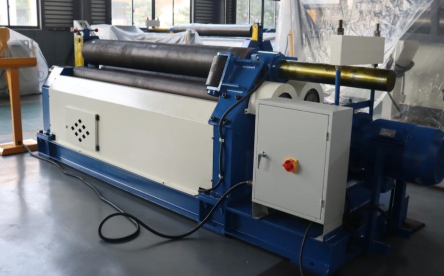
المبدأ: في آلة ثني الصفائح المتماثلة، يتحرك الأسطوانة العلوية عموديًا لأعلى ولأسفل عبر الزيت الهيدروليكي داخل أسطوانة هيدروليكية تؤثر على مكبسٍ يقع في موضع متماثل بين الأسطوانتين السفليتين. ويُحقَّق هذا الحركة الرأسية بواسطة الترس النهائي لمخفض السرعة الرئيسي، الذي يُدير بدوره الأسطوانتين السفليتين للدوران، موفِّرًا عزم الدوران اللازم لثني صفائح المعدن. وتمر صفائح المعدن المسطحة والبلاستيكية بين الأسطوانتين العاملتين الثلاث (أسطوانة سفلية اثنتان وأسطوانة علوية واحدة). وتؤدي الضغطة التنازلية للأسطوانة العلوية وحركة الدوران للأسطوانتين السفليتين إلى خضوع الصفيحة المعدنية لسلسلة من عمليات الثني المتتالية (تشوه انضغاطي في الطبقة الداخلية، وثبات في الطبقة الوسطى، وتشوه شدّي في الطبقة الخارجية)، ما يؤدي إلى تشوه بلاستيكي دائم وتشكيل الصفيحة إلى الأسطوانة أو المخروط أو جزءٍ منه حسب المطلوب. ومن عيوب هذه الآلة الهيدروليكية ذات الأسطوانات الثلاثة أن طرفي الصفيحة المعدنية يتطلبان ثنيًا أوليًّا باستخدام معدات أخرى. وهذه الآلة مناسبة لعمليات لف الصفائح على نطاق واسع عندما تكون سماكة الصفيحة ٥٠ مم أو أكثر. كما أُضيف صفٌّ من الأسطوانتين الداعمتين الثابتتين في الجزء السفلي من الأسطوانتين السفليتين لتقصير الباع بينهما، وبالتالي تحسين دقة القطعة الملفوفة وأداء الآلة العام.

تُستخدم آلة تشكيل الصفائح ذات الأسطوانات الثلاثية على نطاق واسع في قطاعات الطاقة والنقل والنفط والكيماويات وصناعة الغلايات وبناء السفن والطاقة الكهرومائية وهيكل المعادن. ويمكنها تشكيل قطع العمل المخروطية والدائرية والمنحنية.
الميزات الرئيسية:
١. تتحدد أقصى سعة تشغيلية لآلة تشكيل الصفائح بأربعة عوامل رئيسية: أقصى سمك مسموح به للصفائح (أي سمك التقويس الأولي)، وأقصى عرض للصفائح، ونوع المادة الخام المستخدمة في الصفائح، وأصغر قطر مسموح به للأسطوانات عند أعلى سعة قياسية. وتشكل العلاقة بين هذه العوامل الأربعة أثناء التشغيل ما يُعرف بعلاقة التحويل للسعة التشغيلية للآلة، وتُقدَّم هذه العلاقة للمستخدم في دليل التعليمات المرفق لتسهيل الاستخدام الأمثل للمعدات.
٢. يمكن لهذه الآلة لف القطع الشكلية المخروطية. وعند لف القطع الشكلية المخروطية، وبسبب كون القوة عند أحد الطرفين أكبر نسبيًّا، فيجب أن تكون سعة اللَّف للقطع المخروطية تساوي ٦٠٪ من سعة الآلة، كما ينبغي ألا يتجاوز ميل المخروط عمومًا ٣٠ درجة. ومع ذلك، وبانخفاض سماكة وعرض الصفيحة، تنخفض حمولة المعدات، ويمكن بالتالي زيادة ميل المخروط.
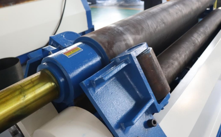
٣. القُطبين السفليين كبيرا القطر وذوا قوة كافية، ولذلك لا تتطلب المعدات بكرات دعم إضافية، ما يقلل فعّاليًّا من معدل أعطال المعدات.

