





How Does a Punching Machine Work and Why Would You Use One?
When it comes to productive metalworking, grasping how a punching machine actually works matters a great deal. If you have been wondering how these machines run, and why manufacturers depend on them so heavily, you are in the right place. In the article below I explain how punching machines function, how they are set up, and the main reasons they remain indispensable in metal fabrication. Whether you are weighing automation or trying to lift production quality, this guide offers the practical insight you need.
How Does a Punching Machine Work?
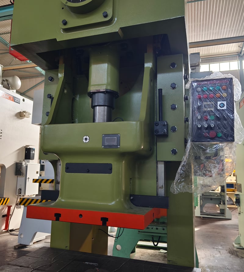
A punching machine works by driving a controlled force through a punch and die set, which produces holes or shapes in sheet metal or other materials. The punch descends on the workpiece with considerable force and shears it against the die, leaving a clean and accurate cut. Modern machines commonly rely on hydraulic, mechanical, or CNC systems to gain speed and precision. Grasping this working process is the key to getting high-quality results while keeping waste low.
Punching Machine Features
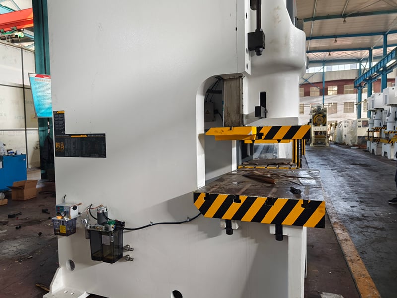
1. The operating interface is easy to use: you simply enter the hole coordinates for the product and the machine processes it, with no programming required.
2. The numerical control screen makes the interface more intuitive and convenient to operate.
3. The processing range is broad, since changing the die lets the machine produce holes of many different sizes and shapes.
4. Pneumatic feeding paired with hydraulic punching gives steady and stable operation.
5. The machine can keep punching an unlimited number of holes in succession, and the resulting holes come out free of burrs, which looks simple and clean.
6. The tool is simple to adjust and dies can be swapped quickly, which saves a great deal of setup time.
7. Automated processing delivers strong consistency, so product quality stays more stable.
Punching Machine Scope
1. In the power sector: cross-arms on 10KV distribution networks, reaming and repairing holes in iron towers, and opening holes; also openings in copper and aluminum busbars, equipment line clamps, flat steel, and similar parts at power plants and substations.
2. For inspection and reinforcement work in the rail, post and telecommunications, petroleum, geological, and construction industries. Because the machine does not need electrical power, it is particularly well suited to field, high-altitude, and underwater jobs.
Punching Machine Notes
1. Before operating, confirm that the punch and die match; otherwise the host machine can be damaged.
2. The die must be tightened with screws before punching.
3. If an abnormal fault appears during operation, stop punching and clear the fault so the machine is not damaged.
4. The screw and nut should be oiled for lubrication.
The Working Principle of the Punching Machine
The principle is that the engine keeps the inertia wheel running. When the machine is not activated, the inertia wheel continues storing energy through the spring. Once the pedal is stepped on, the energy accumulated in the inertia wheel is carried along the transmission guide; when the rod transfers it to the drill bit, a punch is driven into the object.
Punching Machine Classification
Today these machines fall mainly into CNC and hydraulic types. The first type is used chiefly for punching softer products such as leather, plastic, PVC, and paper. The second type is generally applied to punching holes in metal sheets such as copper sheet, steel sheet, and angle iron, and is especially suitable for work in the power and construction industries.
Note On the Punching Machine
Punching machines are generally suited to softer materials, and gravity is used to drive the drill bit down during processing, so pay attention to applying an appropriate lifting force, or the material being processed may crack. Do not look downward while operating, so that waste cannot injure your eyes, and never put your hands within the stamping zone; also make sure no unrelated workers stand inside the danger range.
Introduction of Punching Machine Structure
Punching machines come in many types, and because their structural principles differ, price and processing results vary accordingly. Even so, presses of different types always share certain structural commonalities. This section introduces some common structures and parts of presses and explains their characteristics and functions, so you can understand and use presses more effectively.
Brief Structure
Upper mold: the upper portion of the complete punching die, meaning the part that is mounted on the press slide.
Upper mold holder: the topmost plate of the upper mold; during work it sits close to the press slide and is fixed to it either through the mold handle or directly.
Lower mold: the lower portion of the complete die, meaning the part that is mounted on the press table.
Lower mold holder: the plate forming the bottom surface of the lower mold, fixed directly to the press table or to the pad during work.
Edge wall: the side wall along the edge of the die hole used for punching.
Edge slope: the incline on each side of the edge wall of the blanking die hole.
Air cushion: a pop-up device driven by compressed air.
Reverse side pressure block: the component that supports the one-way force convex mold from the opposite side of the working surface.
Guide sleeve: a tubular part that gives precise guidance to the relative motion of the upper and lower mold holders; it is usually fixed in the upper holder and works with the guide pillar fixed in the lower holder.
Guide plate: a plate with a precise sliding hole around the convex mold, used to keep the convex and concave molds aligned and to strip material and pieces.
Guide pillar: a cylindrical part that gives precise guidance to the relative motion of the upper and lower holders, usually fixed in the lower holder and paired with the guide sleeve fixed in the upper holder.
Guide pin: a pin-shaped part that enters the hole in the material to guide its position within the concave mold.
Guide plate mold: a die guided by a guide plate, in which the convex mold does not separate from the guide plate while the die is in use.
Guiding plate: a plate-shaped guiding part that directs strip or roll material into the concave mold.
Guide pillar mold holder: a mold holder in which the guide pillar and guide sleeve slide against each other.
Punching mold: process equipment installed on the press to produce punched parts; it consists of upper and lower halves that fit each other.
Convex mold: the raised portion of the die that directly forms the punched part, that is, the part carrying the shape of the working surface.
Concave mold: the recessed portion of the die that directly forms the punched part, that is, the part carrying the inner shape of the working surface.
Protective plate: a plate part that keeps fingers or foreign objects out of the dangerous zone.
Pressing plate (circle): the die part that holds down the stamping material or workpiece in order to control material flow; in deep-drawing dies most pressing plates are called pressing circles.
Crimping tendon: a rib-like protrusion used to control material flow in a drawing or deep-drawing die; it may be a local feature of the die or crimping ring, or a separate part set into the die or ring.
Pressed material threshold: the special name for a pressed-material bar with a rectangular cross section; it is described together with the pressing tendon.
Material carrier plate: a plate part that extends the upper plane of the concave mold in order to support the pressed material.
Continuous mold: a die with two or more stations, where material is fed one station at a time with each press stroke so that the punched part is formed gradually.
Side edge: a convex mold that cuts a feeding-position notch in the side of strip or coil material.
Side pressure plate: a plate part that presses one side of the strip or coil material with a spring so that the other side stays close to the guide plate.
Top bar: a rod-shaped part that directly or indirectly ejects the workpiece or scrap with an upward action.
Top plate: a plate part that moves within the concave mold or module to eject the workpiece or scrap directly or indirectly by moving upward.
Ring: a ring-shaped tooth protrusion on a fine blanking die or on a toothed pressing plate; it is a local feature of the die or toothed plate rather than a separate part.
Limit sleeve: a tubular part that limits the minimum closing height of the die, usually placed outside the guide pillar.
Limit column: a column-shaped part that limits the minimum closing height of the die.
Positioning pin (plate): a part that holds the workpiece in a constant position inside the die; depending on its shape it is called a positioning pin or a positioning plate.
Fixed plate: a plate part that secures the convex mold.
Fixed unloader plate: the stripper plate that is fixed on the die in a position that cannot move.
Fixed stopper pin (plate): a stopper pin or plate that is fixed inside the die.
Unloader: a non-plate part or device that removes the workpiece or scrap from the outer surface of the die.
Unloader plate: a fixed or movable plate-shaped part that removes material or workpieces from the die; sometimes it is made as one piece with the guide plate and also guides material, yet it is still called the unloading plate.
Unloading screw: a screw fixed to the pop-up unloading plate, used to limit the static position of that plate.
Single process mold: a die that completes only one operation in a single stroke of the press.
Scrap cutter: two kinds exist: one is a cutter mounted on the flange cutting-edge die to cut the full ring of edge scrap so it can be removed more easily; the other is a cutter mounted on the press or die to cut strip or roll scrap to a fixed length for easier removal.
Combination punching mold: a universal, adjustable set of punching dies that builds various punched parts step by step according to geometric elements such as straight line, angle, arc, and hole; the outline of a flat punched part generally needs several sets of combination dies to be punched in stages.
The starting stopper pin (plate): a part used for positioning when feeding the starting end of the material; these starting stopper pins and plates are movable.
Piece: a complete concave mold, convex mold, unloading plate, or fixed plate, and so on.
Block (plate): a part that positions the hardened components at the side edge of notched material feeding and balances the one-sided cutting force of the side edge; it is generally used together with the side edge.
Stopper pin (plate): a part that positions material along the feed direction; its different shapes are called stopper pin or stopper plate. The term covers fixed stopper pins and plates, movable stopper pins and plates, starting stopper pins and plates, and the like.
Pad: a hardened plate part placed between the fixed plate or concave mold and the die base in order to reduce unit compressive stress on the die base.
Detailed Structure
The die mounted on the press is the upper mold, that is, the portion installed on the press slide. The lower mold is the lower portion, installed on the press table. The lower mold holder is the plate on the bottom side of the lower mold. The edge wall is the side wall at the edge of the punching die hole. The slope of the edge is the incline on each side of the die wall. The air cushion is a pop-up device driven by compressed air. The counter press is a part that supports the one-way stressed mold from the other side of the working surface.
The punching guide is a tubular component designed to keep the upper and lower mold holders precisely aligned during operation. It is usually fixed to the upper mold holder and works together with a guide pillar mounted on the lower mold holder. Meanwhile, the guide pin is a pin-shaped part inserted into the hole in the material so as to position it accurately inside the concave mold, ensuring correct placement during punching.
The guide plate, on the other hand, is a plate-shaped component that directs strip or rolled material into the concave mold. In a guide plate mold, the convex mold remains attached to the guide plate while in use, maintaining alignment throughout the operation. In addition, the guide post mold holder is the type of holder where the guide post and guide sleeve slide against each other, which allows smooth and precise movement.
A punching mold is a process tool installed on a press machine to produce punched parts. It consists of two matching sections: the upper and the lower mold. The convex mold is the raised portion that directly shapes the punched part, while the concave mold is the recessed portion that complements it and also helps determine the final form of the part. To keep operation safe, a protective plate is installed to prevent fingers or foreign objects from entering the hazardous area around the die.
The press bar is a rib-like protrusion found in drawing or deep drawing dies and is designed to control material flow during forming. It can be an integrated part of the concave mold or of the pressing ring. When the press bar has a rectangular cross-section, it is specifically called a pressing sill. In addition, a supporting plate extends the upper surface of the die to provide extra support for the material being pressed.
The side edge of the press is a convex mold designed to cut a positioning notch along the side of the strip or coil material, which helps ensure proper alignment during processing. The side pressure plate uses a spring mechanism to press one side of the strip or coil, thereby forcing the opposite side tightly against the guide plate for accurate positioning. The top bar is a rod-shaped component that directly or indirectly pushes the workpiece or scrap upward so that it can be removed from the die.
The top plate operates inside the die or module, moving upward to eject the workpiece or scrap either directly or indirectly. The limit sleeve is a tubular component used to restrict the minimum closing height of the die and prevent over-compression. Similarly, the limit post is a post-shaped part that also defines and maintains the minimum closing height during operation, ensuring consistent and safe performance.
The punch fixing plate is the plate that holds the mold. The fixed unloading plate is a plate that is fixed to the die in a position that cannot move. The fixed stopper pin, or fixed stopper plate, is a stopper fixed inside the die. The unloader is a non-plate part or device that removes the workpiece from the outer surface of the die. The unloading screw is a screw fixed to the pop-up unloading plate.
A single process mold completes only one operation in one stroke of the press. There are two types of scrap cutters. Combination molds are universal, adjustable sets of dies that form various punched parts step by step according to geometric elements such as a straight line, angle, arc, or hole. The outline of a flat punched part generally requires several sets of combination dies to be punched in stages. The starting stopper pin, or starting stopper plate, is a part used for positioning when the starting end of the material is fed. A block is a complete concave mold, convex mold, unloading plate, or fixed plate, and so on. The block plate is generally used together with the side edge.
Conclusion
Understanding how a punching machine works is essential to unlocking faster and more efficient production in metal fabrication. By mastering the setup, operation, and maintenance of your machine, you can maximize productivity while minimizing downtime and waste.
If you are ready to explore high-performance punching solutions, or need expert advice on selecting the right machine for your factory, feel free to contact our JUGAO team for personalized support.

