


ESA S875 დიეს დაყენების ნაბიჯ-ნაბიჯ სახელმძღვანელო
CNC პრეს-ტორსის მუშაობის დროს ESA S875 კონტროლერზე დიების დაყენება არის გასაღები ეტაპი სწორი გამოხვევის შედეგების მისაღებად და უსაფრთხო, შეჯახების გარეშე წარმოების უზრუნველყოფად. თუ თქვენ ეძებთ ESA S875 დიების სწორი დაყენების პროცედურებს და კონტროლერზე დიების სწორი არჩევანის, შეყვანის და კონფიგურირების მეთოდებს, ეს სახელმძღვანელო მოგაწოდებს გასაგებ და განხორციელებად პასუხებს. ეს სტატია სრულად აშკარავებს ESA S875 დიების დაყენების პროცესს პრაქტიკული, ნაბიჯ-ნაბიჯ ინსტრუქციების სახით და ეხმარება გაგებაში, თუ როგორ აისახება დიების არჩევანი, ნახაზების და მონაცემების მართვა გამოხვევის სიზუსტესა და მანქანის მუშაობაზე. მიუხედავად იმისა, ახალი ხართ თუ არ ხართ ESA S875 კონტროლერზე, ან საკუთარი დაყენების სამუშაო გზის ოპტიმიზაციას ეძებთ, ეს სახელმძღვანელო საშუალებას მოგაძლევს სწორად შეასრულოთ დიების დაყენება და გააუმჯობესოთ თქვენი პრეს-ტორსის სრული ექსპლუატაციური ეფექტურობა.
ESA S875 კონტროლერზე დიების სიის წვდომა
Ნაბიჯი 1: ESA S875-ზე დიების სიის ჩვენება
ESA S875 ჭარბდაჭრის დაყენების პროცესის დასაწყებად ჯერ უნდა მიუწვდეთ კონტროლერის ინტერფეისზე არსებულ ინსტრუმენტების სიას.

Დააჭირეთ შესაბამის კლავიშს, რათა ეკრანზე გამოჩნდეს ან ხარისხის სია, ან ჭარბდაჭრის სია.
Თუ ეკრანზე ხარისხის სია გამოჩნდება, დააჭირეთ იგივე კლავიშს ხელახლა, რათა გადაისვალოთ ჭარბდაჭრის სიაზე.
Როგორც კი ჭარბდაჭრის სია გამოჩნდება, ეკრანი სამ ფუნქციონალურ ნაკრებად იყოფა:
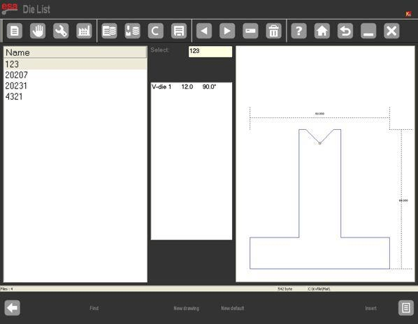
• მარცხენა ფანჯარა: აჩვენებს ხელმისაწვდომი ჭარბდაჭრების სრულ სიას
• ცენტრალური ფანჯარა: აჩვენებს მონიშნული ჭარბდაჭრის დეტალურ განზომილებათა მონაცემებს
• მარჯვენა ფანჯარა: აჩვენებს მონიშნული ჭარბდაჭრის გრაფიკულ წინასანახავს
Ეს ინტერფეისის განლაგება საშუალებას აძლევს ოპერატორებს სწრაფად იდენტიფიცირებას საჭიროებული ჭარბდაჭრის, რაც განსაკუთრებით სასარგებლოა დიდი რაოდენობის ინსტრუმენტების მარაგის მართვის დროს.
2-ლი ნაბიჯი: წინასანახავისა და არჩევის ფუნქციების გამოყენება
ESA S875-ის დაყენების დროს სწრაფად ჭარბდაჭრის იდენტიფიცირების მიზნით შეგიძლიათ ჩართოთ წინასანახავის ფუნქცია, რომელიც მონიშნული ჭარბდაჭრის ვიზუალურ გრაფიკულ გამოსახულებას აჩვენებს.
Თუ წინასაყურედ ჩვენების ფუნქცია არ არის საჭიროებული, მის გამორთვა შესაძლებელია სისტემის მენიუდან — აირჩიეთ [წინასაყურედ ჩვენება] და გადაადგილეთ გადამრთველი გამორთვის მიზნით; იგივე მოქმედება ხელახლა ჩართავს მას საჭიროების შემთხვევაში.
Ინტერფეისზე ნავიგაციის ეფექტურობის გასაუმჯობესებლად:
• დააჭირეთ [სიას] კურსორის დაბრუნებისთვის ჭედების სიაში
• დააჭირეთ [არჩევანს], რათა ხელით შეიყვანოთ ჭედის სახელი და სწრაფად იპოვოთ კონკრეტული ინსტრუმენტი
Პირდაპირი სრიალება შეხების პანელზე ასევე მხარდაჭერილია, რაც დიდი რაოდენობის ჭედების სანახავად უფრო მარტივს ხდის.
Ჭედების მონაცემების მართვა ESA S875-ზე
3-ე ნაბიჯი: ჭედების კოპირება, გადარქმევა და წაშლა
Ჭედების მონაცემების ეფექტური მართვა ESA S875 კონტროლერის გრძელვადიანი, ეფექტური გამოყენების ერთ-ერთი მთავარი ასპექტია.
Სისტემა ჭედების მართვის შემდეგ ძირითად ფუნქციებს სთავაზობს:
• ჭედის კოპირება: არსებული ჭედის გაზომვების საფუძველზე ახალი ჭედის შექმნა, რაც მსგავსი მოთხოვნების მქონე გამოხრის აპლიკაციებისთვის იდეალურია
• ჭარხლის გადარქმევა: დაამკაცეთ ჭარხლების სახელწოდების ერთიანი, სტანდარტული წესები მათი მარტივად იდენტიფიცირების მიზნით
• გამოუყენებელი ჭარხლების წაშლა: შეიძლება შეამციროს ჭარხლების ბაზის დატვირთულობა და შერჩევის შეცდომების რისკი
Ეს ფუნქციები ხელს უწყობს საჭარხლე ბიბლიოთეკის მოწესრიგებულად შენახვას — რაც მნიშვნელოვანი პრაქტიკაა მრავალკომპონენტიანი წარმოების გარემოში ან რამდენიმე სამუშაო ცვლილებით მომუშავე საწარმოებში.
Ახალი ჭარხლის შეტანა ESA S875-ში
Ნაბიჯი 4: გამოხატული ჭარხლებისა და წინასწარ დაყენებული ჭარხლების შორის არჩევანი
Როდესაც ახალი ჭარხლი შეიტანება ESA S875 სისტემაში, ხელმისაწვდომია ორი დაყენების მეთოდი:
• წინასწარ დაყენებული ჭარხლები: წინასწარ განსაზღვრული ჭარხლების ტიპები ფიქსირებული, მოსარეგულირებლად პარამეტრებით
• სრულად გამოხატული ჭარხლები: სრულიად ახალი ჭარხლები, რომლებიც შეიქმნება ნულიდან უნიკალური განზომილებებითა და ფორმებით
Წინასწარ დაყენებული ჭარხლები რეკომენდება მაშინ, როდესაც ფაქტობრივი საჭარხლე მოწყობილობა მკაფიოდ ემთხვევა სისტემის წინასწარ განსაზღვრული ჭარხლების ერთ-ერთ ტიპს, რადგან ეს შეიძლება მნიშვნელოვნად შეამციროს დაყენების დრო. სრულად გამოხატული ჭარხლები აუცილებელია შემდეგ შემთხვევებში:
• ჭარხლი არ ემთხვევა არცერთ წინასწარ დაყენებულ კატეგორიას
• დამშენებლის ფორმა მრავალკვეთიანია
• დამშენებლის ფორმა სპეციალურია — კვადრატული ან წნევის კვეთით
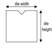
Სწორი დამშენებლის შეყვანა განსაკუთრებით მნიშვნელოვანია: დამშენებლის ნახაზი გამოიყენება სისტემის შეჯახების გამოსავლენად, ხოლო გამოხვევის სიღრმის გამოთვლები სრულიად დამოკიდებულია კონტროლერში შეტანილ განზომილებათა მონაცემებზე.
5-ე ნაბიჯი: სრულად დახაზული დამშენებლის შექმნა
Არასტანდარტული ინსტრუმენტების შემთხვევაში ESA S875 საშუალებას აძლევს სრულად მორგებული დამშენებლის ნახაზის შექმნას [ახალი ნახაზი] ფუნქციის საშუალებით.
Დამშენებლის სიმაღლისა და სიგანის პარამეტრების შეყვანის შემდეგ სისტემა გახსნის ნახაზის ინტერფეისს, რომელიც ორი ძირითადი ნაკრებისგან შედგება:
• მთავარი ნახაზის ფანჯარა მარცხენა მხარეს — ვიზუალური დამშენებლის დიზაინისთვის
• პარამეტრების შეყვანის ფანჯრები მარჯვენა მხარეს — პოლარული, კარტეზიანული, V-კვეთის და კვადრატული კვეთის განზომილებების შესატანად
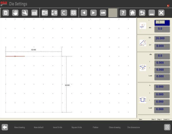
Დამშენებლები საათის ისრის მიმართულებით უნდა დაიხაზოს, ხოლო შეჩერების პოზიცია უნდა მოთავსდეს მარჯვენა მხარეს. ეს უზრუნველყოფს კომპიუტერული რიცხვითი მართვის (CNC) სისტემის სწორად ინტერპრეტაციას დამშენებლის დიზაინზე.
6-ე ნაბიჯი: წინასწარ დაყენებული დამშენებლების რედაქტირება და შენახვა
Წინასწარ დაყენებული კალაპოტები გამოისახება წინასწარ დახაზული ფორმების სახით რეგულირებადი პარამეტრებით. როგორც კი თქვენ გადაადგილდებით მონაცემთა ველებში და ცვლით მნიშვნელობებს, კალაპოტის ნახაზზე შესაბამისი განზომილება რეალურ დროში გამოიკვეთება, რაც პარამეტრების რეგულირებას ინტუიციურ და სიზუსტის მაღალი დონის ხდის.
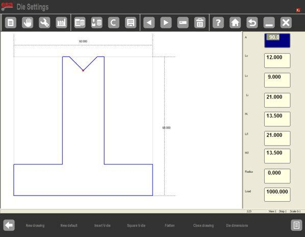
Საჭიროების შემდეგ პარამეტრების შეცვლის შემდეგ დაადასტურეთ ცვლილებები [ENTER] ღილაკის დაჭერით — სისტემა ავტომატურად განაახლებს კალაპოტის ნახაზს ახალი მნიშვნელობების მიხედვით.
Როგორც კი წინასწარ დაყენებული კალაპოტის დაყენება დასრულდება, შეინახეთ კალაპოტი უნიკალური სახელის შეყვანით და [OK] ღილაკის დაჭერით. შენახული კალაპოტები შემდგომში შეიძლება გამოყენებულ იქნას სხვა გამოხვევის პროგრამებში, რაც მომდევნო დაყენების პროცესებს მარტივდება.
ESA S875 კალაპოტის დაყენების საუკეთესო პრაქტიკები
ESA S875 კონტროლერზე სწორად შესრულებული კალაპოტის დაყენება არ აუმჯობესებს მხოლოდ გამოხვევის სიზუსტეს, არამედ ამცირებს ინსტრუმენტების შეჯახების რისკს და ამაღლებს წარმოების ერთნაირობას. ოპტიმალური შედეგების მისაღებად ყოველთვის მიჰყევით შემდეგ საუკეთესო პრაქტიკებს:
• დარწმუნდით, რომ შეყვანილი კალაპოტის განზომილებები სრულად ემთხვევა ფაქტიური ინსტრუმენტების განზომილებებს
• მიახლოებით სწორი მიმართულების წესების დაცვა მომხმარებლის მიერ შექმნილი ჭრის ინსტრუმენტების გასახატად
• სისტემიდან რეგულარულად ამოიღეთ გამოუყენებელი ან მოძველებული ჭრის ინსტრუმენტების მონაცემები
Მუდმივი და სწორი ჭრის ინსტრუმენტების მართვა უზრუნველყოფს პრეს-ბრეიკის უსაფრთხო და ეფექტურ მუშაობას მრავალი სახის ჩამოხრების მომსახურების განმავლობაში.
Ხშირად დასმული კითხვები (FAQ)
Როდის უნდა გამოვიყენო წინასწარ დაყენებულ ჭრის ინსტრუმენტებს ESA S875-ზე სრულად დახატული ჭრის ინსტრუმენტების ნაცვლად?
Გამოიყენეთ წინასწარ დაყენებული ჭრის ინსტრუმენტები, როდესაც ფაქტობრივი ინსტრუმენტები მჭიდროდ ემთხვევა ESA S875 სისტემაში წინასწარ განსაზღვრული ჭრის ინსტრუმენტების ერთ-ერთ ტიპს. წინასწარ დაყენებული ჭრის ინსტრუმენტები სწრაფ დაყენებას და მარტივ პარამეტრების შეცვლას უზრუნველყოფს. სრულად დახატული ჭრის ინსტრუმენტები უკეთესი არჩევანია, როდესაც ჭრის ინსტრუმენტს რამდენიმე სივრცე აქვს, სპეციალური ფორმა ან ის არ ემთხვევა სისტემის წინასწარ დაყენებული კატეგორიების არც ერთს.
Შემიძლია თუ არა არსებული ჭრის ინსტრუმენტის ასლის შექმნა ESA S875-ის ჭრის ინსტრუმენტების დაყენების დროს?
Კი. ESA S875 კონტროლერი საშუალებას გაძლევთ არსებული დიეს დააკოპიროთ და შეინახოთ ახალი სახელით. ეს ფუნქცია განსაკუთრებით სასარგებლოა მსგავსი დიების შესაქმნელად მცირე გაზომვის შეცვლებით, რადგან ის ამცირებს მოწყობილობის მორგების დროს და უზრუნველყოფს საწარმოს პროცესებში ინსტრუმენტების მონაცემების ერთიანობას.
Რა არის საერთო შეცდომები, რომლებიც უნდა არ დაიშვას ESA S875 დიეს მორგების დროს?
Ყველაზე გავრცელებული შეცდომები მოიცავს არასწორი დიეს გაზომვების შეყვანას, დიეს არასწორი მიმართულებით დახაზვას და სისტემიდან მოძველებული ან არასწორი დიეს მონაცემების გამოყენებას. ამ პრობლემების თავიდან ასაცილებლად ყოველთვის შეამოწმეთ დიეს ფაქტობრივი გაზომვები მონაცემების შეყვანამდე, მიყევით სისტემის მიერ მითითებულ მიმართულებას მორგებული დიეს დახაზვის დროს და შეასრულეთ რეგულარული მოვლა ESA S875-ის დიეს მონაცემთა ბაზაზე.
Დასკვნა
ESA S875-ის საჭიროების შესაბავად სწორი დიეს დაყენება საკვანძო მნიშვნელობის მოახდენს სწორი გამოხვევის შედეგების მიღებაში, საიმედო შეჯახების გამოვლენაში და სტაბილურ პრეს-ბრეიკის მუშაობაში. სტანდარტული პროცედურების მიხედვით — დიეს სიის წვდომა, წინასწარი დათვალიერებისა და არჩევის ფუნქციების გამოყენება, დიეს მონაცემების ეფექტური მართვა, ახალი დიეს შეყვანა და შესაბავად შესატყობარო მეთოდის (სრულად დახაზული ან წინასწარ დაყენებული) არჩევა — ოპერატორებს შეუძლიათ ESA S875 კონტროლერის ეფექტურად დაყენება და დაყენების შეცდომების მინიმიზაცია. სწორი დიეს განზომილებათა მონაცემები და სწორი ხაზვის წესების დაცვა პირდაპირ გამოიხატება გამოხვევის სიზუსტეში და მანქანის უფრო უსაფრთხო მუშაობაში.
Საუკეთესო წარმოების შედეგების მისაღებად რეკომენდაციას ვაძლევთ დიეს ბიბლიოთეკის კარგად მოწყობილ შენახვას, წარმოების დაწყებამდე ყველა დიეს პარამეტრის შემოწმებას და შესაძლებლობის ფარგლებში წინასწარ დაყენებული დიეს გამოყენებას, რათა დაეზოგოს მნიშვნელოვანი დაყენების დრო.
ESA S875 კონტროლერის, საჭაპანო ინსტრუმენტების ან ინდივიდუალურად შექმნილი გამოხრის ამოხსნების შესახებ დამატებითი ტექნიკური მიმართვის მისაღებად მიმართეთ HARSLE-ს პროფესიონალური მხარდაჭერის მისაღებად ან გაეცნოთ შესაბამისი ტექნიკური დოკუმენტაცია და პროდუქტის რესურსები ჩვენს ოფიციალურ ვებგვერდზე.

