


How to Operate the DELEM DA-53T CNC Press Brake: A Complete User Manual
This manual serves as a comprehensive guide to the setup and operation of the DELEM DA-53T CNC press brake, designed to help you master the equipment’s operation and ensure high-precision, efficient bending performance. Below is a step-by-step breakdown of the machine’s configuration, functional operation, and programming processes to achieve optimal working results.
Table of Contents
1. Operational Overview and General Introduction
2. Title Panel
3. Information Panel
4. Command Panel
5. Navigation Panel
6. Product Library
7. Tool Configuration
8. Product Programming
9. Bending Methods
10. Automatic Mode
11. Available View Modes
12. Manual Mode
13. System Settings
14. Data Download
15. Video Demonstrations
1. Operational Overview and General Introduction
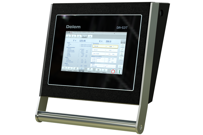
1.1 The Control Unit
The physical design of the DELEM DA-53T control unit may vary slightly by device, but its core operation is realized through a touchscreen interface. Detailed descriptions of all touchscreen functions and operable controls are provided in the subsequent sections of this manual, alongside explanations of specific functional applications.
1.2 Front Control Buttons
The touchscreen user interface integrates core start and stop buttons, which are the primary physical control elements for initiating and halting machine operations.
1.3 USB Connectors
A USB port is located on the right side of the control unit, enabling connection to external devices such as USB flash drives, external keyboards, and mice for data transmission and auxiliary operation.
1.4 Operation and Programming Modes
The control unit’s main screen displays different content based on the active navigation button, with the Products function interface as the default main screen. Users can switch to the corresponding functional mode simply by tapping the on-screen mode options. The main screen is structurally divided into the Title Panel, Information Panel, Command Panel, and Navigation Panel, each with dedicated functional positioning.
1.5 Getting Started
1. Basic Programming Logic: The control unit supports creating bending programs for products step-by-step, and users can independently adjust specific parameters for each individual bending step to meet customized processing needs.
2. Preparatory Work: Prior to initiating product programming, complete all required preparatory procedures as specified to ensure the programming and operation process is error-free.
3. Program Modification: The Program menu provides access to the numerical program and parameter values of the currently active product. Existing programs can be modified here—users can select individual bending steps, check programmed parameters in real time, and adjust values as needed. The system will automatically calculate axis positions based on the machine’s configuration parameters.
4. Production Modes (Auto & Manual):
○ Auto Mode: Executes pre-set product programs in sequence, completing each bending step automatically. It also supports Step mode, where each bending step is initiated manually by the user.
○ Manual Mode: An independent production mode for programming and executing a single bending step, primarily used to test the operational performance of the bending system.
For detailed operations, refer to Chapters 5 and 6 of this manual.
5. Data Backup & External Storage: Product programs and tool configuration files can be stored on external USB flash drives. This not only provides a secure backup for important data but also enables file sharing and exchange between different DELEM control units. For detailed backup and transfer methods, refer to Chapter 7.
1.6 Programming Aids
The control unit is equipped with a range of user-friendly programming auxiliary functions to simplify the parameter setting process and improve programming efficiency:
1. Listbox Functionality: For parameters with a limited set of optional values, tapping the parameter line on the screen will pop up a drop-down list of options at the tap position, allowing direct selection of the desired value.
2. Parameter Zoom Functionality: When programming key parameters (e.g., bending force in Program mode), the system automatically enlarges the corresponding parameter line to enhance visibility and facilitate fine-tuning of values.
3. Tabbed Navigation: Program screens in partial modes are divided into multiple tabs, enabling quick switching between different functional modules for streamlined operation.
4. Text Input & Editing: Tap the target input position to bring up a cursor, and enter numerical values or text directly at the cursor location for precise parameter editing.
5. Alphanumeric & Special Character Input: The on-screen keyboard supports both alphanumeric and special character input. A full alphanumeric keyboard pops up for text fields, while only numeric keys are displayed for pure numerical fields. Special characters (e.g.,?, %, –) can be accessed via the special character button in the lower-left corner of the keyboard. Long-pressing a letter (e.g., 'a') will display accented special characters (e.g., á, à, â).
6. Messages Centre: Alerts from the PLC, safety systems, and sequencer are centralized in the Messages Centre. A Messages Centre icon appears in the top header bar (next to the keylock icon) when alerts are active; tapping the icon hides alerts for normal programming, and tapping it again restores the alert display. A notification indicator on the icon signals new unread alerts.
7. Keylock Function: Prevents unauthorized modifications to product programs and parameters by locking the control unit, protecting the integrity of pre-set data.
8. Manual Positioning: In Manual and Automatic modes, the manual positioning page features a bottom slider for axis positioning—the sliding distance controls the axis movement speed, and the axis stops when the slider is released. Buttons at both ends of the slider enable fine-tuning of the axis position, and a beep sound provides real-time feedback during axis movement.
9. Software Version Check: The control unit’s software version is displayed on the System Information tab in the Machine menu for easy system maintenance and updates.
2. Product Library
The Products mode is the core interface for managing all product bending programs, supporting the selection, editing, and creation of programs to adapt to different production needs.
2.1 Main View
The Products mode displays an overview of all stored programs in the control unit’s library, with each program entry showing the Product ID, Product Description, Number of Bends, and Last Modified/Used Date. The ID of the currently active product program is displayed at the top of the screen; users can load a program by tapping any area of the corresponding program entry. For libraries with more programs than the screen can display, drag the list upward to view additional entries and tap to select and activate the target program.
2.2 Product Selection
A single tap on a program entry selects and loads it into the control unit’s memory. After loading, users can tap the Auto button to start production directly, or navigate to Tool Setup and the numerical Program interface for parameter adjustments and tool configuration.
2.3 Creating a New Program
Initiate a new numerical bending program by tapping the New Program button. The system will first prompt for basic product information, including Product ID, material thickness, and material type—complete these entries to start programming.
2.4 Editing, Copying, and Deleting Programs
1. Deletion: Tap to select a program entry, then tap Edit and select Delete. Confirm the deletion prompt to remove the program; tap Delete All to erase all stored programs at once.
2. Copying: Select a program entry, tap Edit and choose Copy, enter a new Product ID for the copied program, and confirm. The copied program includes the original’s complete tool setup and all parameter settings for direct reuse or secondary editing.
3. Renaming: Select a program entry, tap Edit and click Rename, then enter the new name to complete the renaming process in one step.
3. Tool Configuration
Tool configuration is a critical step in bending production, ensuring the upper (punch) and lower (die) tools match the product’s processing requirements.
3.1 Basic Operation
Select the target product from the product library and tap Tool Setup to activate the tool configuration interface, which displays the machine’s current active tool setup. Both punches and dies can be selected and replaced from the pre-stored tool library.
3.2 Tool Selection
The interface clearly shows the parameters of the currently used punch and die (e.g., ID, height, angle, radius, V-opening for dies). Tap Select Punch or Select Die to browse the tool library and select the appropriate tool to complete the configuration update.
4. Product Programming
Product programming is the process of setting detailed bending parameters for each step, and the system supports both editing existing programs and creating new ones from scratch.
4.1 Basic Operation
• Edit an Existing Program: Select the target product in the Products overview and tap the Program navigation button to enter the programming interface.
• Create a New Program: After tapping New Program and completing basic product property settings and tool configuration, the system automatically switches to the Program interface.
The programming operation logic is identical for both scenarios. The main interface displays the existing numerical program (or the first bending step for new programs). A bend selector at the top of the screen allows quick navigation between different bending steps—simply tap the indicated step to view and edit its parameters. Command buttons on the side of the main interface provide access to additional views and functional operations.
4.2 Program Mode: Parameter Explanation
The main programming screen displays all configured bending steps, and users can view and edit specific parameters for each step individually. The top row of the screen shows the Product ID and Product Description for quick identification. Core editable parameters include: bending parameters, bending methods, force, speed, auxiliary functions, product properties, tool information, and auxiliary axis settings.
4.3 Edit/View Modes
1. All Bends: Tapping this function displays a comprehensive table of all bending steps, where the entire CNC program can be edited. Users can adjust all bending parameters directly in the table, and perform operations such as swapping, moving, adding, and deleting bending steps. Swipe the screen horizontally to view and edit additional parameter columns.
2. Change Tools: For modifying tool setups, use the Tool Setup menu for global changes. To adjust the tool setup for a single bending step only, tap Change Tools—the system will prompt whether the change applies to the entire program or just the selected step, and automatically switch to the Tool Setup menu for global changes if selected.
3. Product Properties: Tap Product Properties to modify the core parameters of the program (e.g., material, thickness), which apply uniformly to all bending steps of the product.
4. Add Bend: Tapping this button copies the last bending step and adds it as a new step at the end of the program, simplifying the creation of repetitive bending steps.
5. Bumping: Convert a single numerical bending step into a bumping bend step to meet specific processing requirements for thick or special materials.
4.4 Programming Parameters
Parameters in Program mode are set one by one, and the system automatically calculates and updates the impact of modified parameters on other related parameters. The relationship between parameters is visualized using symbols and background colors for intuitive identification:
• Information Symbol: Appears next to parameters that are automatically updated due to the last edited value, indicating a dependent parameter change.
• Star Symbol: Marks parameters whose manually set values differ from the system’s calculated values, helpful for identifying intentional custom settings or parameter limit constraints.
• Error Symbol: Displays for parameters with invalid values (e.g., a hemming bend step programmed without matching hemming tools), alerting users to configuration errors.
5. Bending Methods
The DELEM DA-53T supports a variety of professional bending methods (e.g., air bend, hemming, bumping) adapted to different material types, thicknesses, and product shapes. The corresponding bending method is selected in the Program mode’s parameter settings, and the system automatically matches the optimal processing parameters based on the selected method and tool configuration.
6. Automatic Mode
Automatic mode is the primary production mode for batch processing, enabling fully automated execution of pre-programmed bending steps.
6.1 Basic Operation
Tap the Auto navigation button to switch the control unit to automatic production mode. With an active program loaded, press the Start button to initiate production—the system executes the bending program step-by-step automatically. For pre-stored products in the library with production history, select the product in Products mode and switch directly to Auto mode to start production.
Important Note: After selecting a new bending program, always check the tool type and positioning in the machine; the system will display a check tools warning message when entering Auto mode as a reminder.
The top header of the Auto mode screen displays the selected product ID and description, and the bend selector shows all bending steps in the program. Users can tap a specific step to start production from that point, and the interface displays detailed parameters of the selected step in the current view. The header also shows the repetition count of the current bending step and linked programs (if applicable), with linked programs marked in the last position of the bend selector.
6.2 View Modes
Auto mode offers multiple customizable view modes to adapt to different production scenarios, with the Main view as the default. Select view modes from the right side of the screen; the six available modes are:
1. Main: Displays the numerical parameters and correction values of the current bending step, where correction values can be programmed and adjusted directly.
2. All Bends: Shows a table of all bending steps with all corresponding parameters, enabling global program review and quick parameter checks.
3. Macro: Displays only large-axis values in an enlarged format, making it easy to read axis parameters when operating at a distance from the control unit.
4. Manual Positioning: Enlarges axis values and allows axis selection—adjust the bottom slider from its middle position to control axis movement, and the slider automatically returns to the middle position when released.
5. Corrections: Centralized view and editing of all correction values for the bending program to fine-tune bending precision.
6. Diagnostics: Primarily for service and maintenance use, it monitors the operation of independent axes and the I/O status of the control system. In rare cases, this view can help diagnose operational issues during the bending process.
6.3 Bumping Correction
If the loaded program contains a bumping bend step, the Bumping Corr. function is activated. Tapping this function opens a dedicated window to enter correction values for the bumping bend step, optimizing processing precision for bumping operations.
7. Manual Mode
Manual mode is designed for single-step bending operations, test runs, and small-batch custom processing, with independent tool setup and parameter programming capabilities.
7.1 Basic Operation & Tool Setup
Tap the Manual navigation button to switch to manual production mode. The tool setup programming process in Manual mode is identical to that in Automatic mode, and while the two modes use independent tool setups (supporting completely different configurations), the Automatic mode’s tool setup can be directly applied to Manual mode for convenience.
When switching from Automatic to Manual mode, the system prompts the user to reuse the Automatic mode’s tool setup and issues a warning to check for configuration differences to avoid processing errors. The manual mode tool setup interface displays detailed parameters of the current punch and die, with Select Punch and Select Die buttons for quick tool replacement.
7.2 Programming Parameters & Views
Parameters in Manual mode are set individually, and the system automatically calculates the mutual influence between parameters, with the same symbol and background color visualization as Program mode for parameter relationship identification. The main interface displays all core parameters for the single bending step, including product properties, bending method, tool information, auxiliary axis settings, and correction values.
7.3 Macro View
Similar to Auto mode, the Macro view in Manual mode enlarges and displays only large-axis values, facilitating parameter reading when operating the machine from a distance.
7.4 Manual Axis Movement
1. Basic Movement: Control the movement of each axis through the on-screen slider and fine-tuning buttons, with real-time beep feedback during axis movement.
2. Teach Function: Supports the teach-in method for axis positioning, enabling precise manual calibration of axis positions for special processing needs.
7.5 Corrections
The Corrections view displays the correction values for the single bending step programmed in Manual mode (shown as a single line for easy editing), allowing quick fine-tuning of bending precision.
7.6 Diagnostics
Tapping Diagnostics switches to the axis status monitoring view, which displays the real-time operating state of all available axes. This view can remain active during machine operation, enabling real-time monitoring of the control unit’s performance during the bending cycle to identify and resolve issues promptly.
8. System Settings
The Settings mode (accessed via the Settings navigation button) is used to configure the control unit’s global parameters, including default values, material libraries, data backup, and production constraints—all settings influence the programming and production of new products and can be customized to match actual production needs.
Settings are logically divided into multiple tabs, with the following core functional tabs and their operations:
1. General: Tap the target parameter to modify it. A keyboard pops up for numerical/alphanumeric parameters, while a drop-down list appears for parameters with fixed options. Scroll vertically to view all options for long lists.
2. Materials: Program and manage material properties—edit existing materials, add new materials, or delete unused ones. The control unit supports a maximum of 99 custom materials for diverse processing needs.
3. Backup / Restore: Realize full data backup and restoration for product programs, tool libraries, system settings, and parameter tables. It also supports restoring DLC-format product and tool files from older DELEM control unit models, with dedicated backup/restore functions for the material library.
4. Program Settings: Configure program-related functional switches and parameters (e.g., angle correction programming, Y1/Y2 axis independence, Machine ID check) to customize the programming process.
5. Default Values: Set default parameters for new program creation (e.g., default bending force, speed, retract distance), reducing repetitive parameter input and improving programming efficiency.
6. Computation Settings: Adjust the system’s core calculation parameters (e.g., bend allowance correction, bottoming force factor) to optimize the accuracy of the system’s automatic parameter calculations.
7. Production Settings: Configure production-related parameters, including stock count mode, auto bend change mode, parallelism offset, touch screen lock, pressure correction, clamping correction, and axis safety offsets—all tailored to optimize production efficiency and processing safety.
8. Time Settings: Set the control unit’s display time (enable/disable), adjust the current time, and configure time format (24-hour/12-hour) and date format (e.g., d-m-yyyy) for accurate data recording and time stamping.
9. Data Download & Video Demonstrations
• Operation Download: The control unit supports downloading product programs, tool configurations, and system setting files to external USB devices for data sharing, backup, or transfer between different DELEM equipment.
• Video Demo: Access dedicated video demonstrations for key operations (e.g., program creation, tool setup, Auto/Manual mode operation) to visualize the operation process and help users master the equipment faster.
This manual covers all core operations of the DELEM DA-53T CNC press brake. Following the above steps and guidelines ensures standardized, high-precision, and efficient operation of the machine. For advanced functional applications and troubleshooting, refer to the DELEM official technical documentation or contact professional after-sales support.

