


How to Operate the DELEM DA-41S Manual
Table of Contents
1. Overview of the DELEM DA-41S
2. Operational Guide for the DELEM DA-41S Manual
3. Hardware Components
4. Working Modes
5. Manual Download
6. Video Demonstration
Having trouble with the DELEM DA-41S? This dedicated guide will help you master its operation with ease, streamlining your experience with CNC press brake machines.
To make the most of the DELEM DA-41S manual, begin by getting familiar with the device's interface, setting up parameters correctly, and following the step-by-step configuration instructions. It’s also essential to understand its programming functions to run CNC press brake machines efficiently. This guide breaks down complex operational steps into easy-to-follow actions, making it suitable for both new operators and seasoned professionals alike.
Ready to tap into the full performance of your DELEM DA-41S? Let’s explore the detailed instructions below!
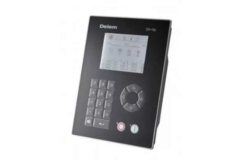
Overview of the DELEM DA-41S
The DELEM DA-41 is a programmable control unit designed for traditional press brake machines. This manual is based on the premise that the DA-41 is set up using the bending depth formula. If the unit is configured to calculate bending depth via tables, please refer to the Version 2 User Manual (8064-901C). If you are unsure about the configured calculation method, reach out to your machine supplier for clarification.
Operational Guide for the DELEM DA-41S Manual
Hardware Components
1. Front Panel
The diagram below shows the layout of the front panel, which features a display screen and a range of keys for programming and axis control. The display functions will be detailed in the next section.
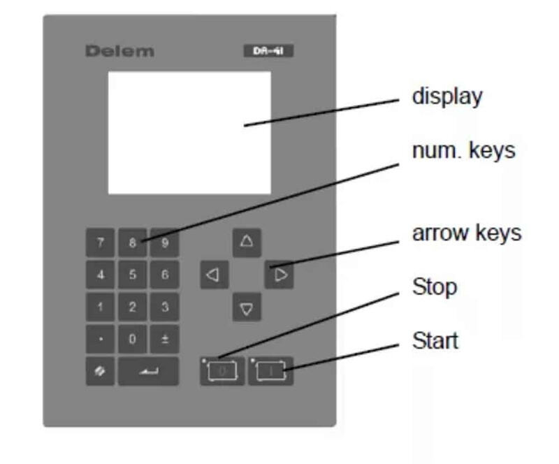
The front panel keyboard includes the following functional keys:
• 10 numeric keys (0–9)
• A decimal point key
• A plus/minus toggle key
• A clear key for erasing parameter values
• An enter key for confirming input values
• Arrow keys for selecting different parameters
• A stop key (marked 0) with a status LED indicator
• A start key (marked 1) with a status LED indicator
2. Display Screen
The DELEM DA-41 is equipped with a 320×240 monochrome LCD display. Different working modes are represented by specific symbols at the top of the screen, allowing operators to quickly identify the current mode.
Working Modes
1. Basic Introduction
The 320×240 monochrome LCD display of the DA-41 clearly marks the active working mode with dedicated symbols at the top of the screen. The available modes include product programming and execution, tool programming, program constants, manual movement, and bend program selection.
2. Basic Navigation Operations
• Mode switching: Press the <arrow up> key until the target mode symbol is highlighted, then use the <arrow left> and <arrow right> keys to navigate to the desired mode.
• Mode entry: Press the <arrow down> key to access the selected mode.
• Parameter navigation within a mode: Use the arrow keys to move the cursor between different parameters and input fields.
• Parameter programming: Move the cursor to the corresponding symbol, enter the required value, and press the ENTER key to confirm. The value is also automatically confirmed when an arrow key is pressed; in some cases, the <arrow left/right> keys can also be used to adjust values.
• Programming restrictions: Steps and their corresponding parameters can only be programmed and viewed when the control unit is in a stopped state.
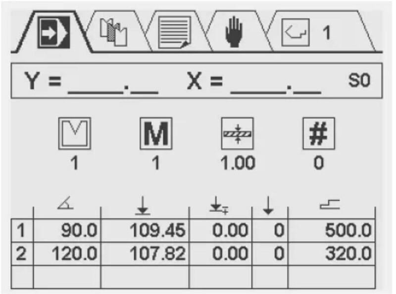
3. Product Programming
The product programming screen is divided into three distinct sections from top to bottom:
• Real-time Y and X axis positions
• General product attributes
• A bend step table, where each step is paired with multiple parameters
The number of the currently active program is shown in the upper right corner of the screen. This screen is used for editing and executing product programs, and a detailed explanation of product programming is provided in Chapter 4 of the manual.
4. Tool Selection
This screen presents a comprehensive overview of all available tools, with a table listing the tool number, V-opening, tool angle, and tool radius. During product programming, the pre-programmed tool attributes are used to calculate the Y-axis values. To set or modify tool attributes, simply move the cursor to the corresponding field of the target tool and enter the desired values directly.
5. Program Constants Setting
The program constants screen allows operators to view and adjust a variety of control unit settings. Editable parameters (excluding read-only ones) can be modified either by using the <arrow left/right> keys or by entering numerical values directly.
Exiting the menu: To exit the program constants menu, either press the <arrow up> key to navigate back to the top symbol menu or press the STOP button to return directly to the automatic production mode.
Service menu access: Enter the code 456 and press the enter key to open the service menu; press the STOP button to exit the menu.
Note: If the enter key is pressed without inputting the specified code, the calibration point will be displayed in read-only mode, and a lock symbol will appear in the upper right corner of the screen to indicate this status.
The service screen enables the programming of the actual calibration point and provides an overview of real-time system information. The specific functions available on the program constants screen vary according to the machine’s technical specifications.
Manual axis movement: On this screen, the X and Y axes can be moved manually using the arrow keys, and this operation is only available when the control unit is not running. Press the <arrow up/down> keys to select the Y or X axis: press the <arrow left/right> keys once for gradual axis movement, or hold down the keys for high-speed axis movement.
6. Product Program Selection
The DELEM DA-41 control unit supports up to 100 product programs, and all programs have 0 steps by default. Once a program is selected, one step is automatically added to it.
Program selection steps:
1. Move the cursor to the target program number and press the ENTER key to select it; the selected program number will be displayed in the upper right corner of the screen next to the mode symbol.
2. For high program numbers (e.g., 74): Press the first digit of the number (7), and the cursor will jump to the group of programs starting with that digit. Then use the arrow keys to locate the exact program number.
After a program is selected, the control unit will automatically switch to programming mode, and the program remains active until another program is selected or the current one is deleted.
Program deletion: Move the cursor to the program number and press the clear key. The program number will be retained, but all its steps will be reset to 0.
7. Key Lock Function
The control unit is fitted with a key lock function to prevent unauthorized programming, and the availability of this function depends on the machine’s specifications.
• Unlocked state: The control unit can be programmed in accordance with the instructions in this manual.
• Locked state: A lock symbol will appear in the upper left corner of the programming window, and the following operational restrictions will take effect:
○ No new programs can be created, and existing programs cannot be edited.
○ Programs cannot be deleted.
○ No new tools can be created, and existing tool parameters cannot be edited.
Even in the locked state, the following operations are still permitted:
• Select pre-existing programs (provided they have one or more steps).
• Execute selected programs.
• Modify Y-axis corrections within active programs.
• Adjust program constants.
• Move the X and Y axes via the manual movement screen.

