


Miks erineb torupainutusmasinast saadud valmistoode oodatud tulemusest?
Toru painutamisel on lõppprodukti ja projekteerimisjooniste või oodatavate tulemuste vahelised erinevused sageli esinev probleem, millega silmitsi seisavad kohapealsed tehnikud. Need kõrvalekalded võivad ilmneda ebatäpsete nurga all, ristlõike deformatsioonina, riputusena, liialdatud tagasipöördumisena või isegi vale ruumilise orientatsioonina. Põhjus on sageli mitte üksainus tegur, vaid materjalide, tikkude, seadmete ja protsesside vahelise tasakaalustamatuse tulemus.
1. Painutusnurga kõrvalekalle
Sümptomid: Tegelik painutusnurk on suurem või väiksem kui seatud väärtus, või sama partii toodete nurgad on ebakorrapäraselt erinevad.
Võimalikud põhjused:
Piisamatu tagasipõrkumise hindamine: Materjalid läbivad painutamise järel elastset taastumist, eriti kõrgtugevusega teras ja roostevabateras. Kui programmist ei reserveerita tagasipõrkumise kompensatsiooniväärtust, siis lõplik nurk on oluliselt väiksem.
Sobimatu ülepainutamise kompensatsiooni seadistus: hüdraulilised või elektrilised torupainutusmasinad on tavaliselt varustatud "ülepainutamisnurga" seadistusega, et kompenseerida tagasipõrkumist. Liialdatud või piisamatu ülepainutamine põhjustab nurga kõrvalekaldumisi.
Mooduli kulunemine: Painutusmooduli tööpinnal tekkinud kulunemine vähendab toru ja mooduli vahelist sobivust, muutes tegelikku painutusraadiust ja mõjutades kaudselt nurga suurust.
1. Piisamatu kinnitumisjõud: Piisamatu kinnitusmatritsi rõhk põhjustab toru libisemise painutamise ajal, mis viib kontrollimatute nurga muutusteni.
2. Toru ristlõike deformatsioon (ellipsjas, tasandatud, sisemine kokkusurumine)
Sümptomid: Lõike ristlõige painde kohas on ellipsjas või esineb selge sisemine kokkukukkumine ja kortsud; tõsistes juhtudes ilmnevad pragud.
Võimalikud põhjused:
Liiga väike painderaadius: R/D väärtus (painderaadiuse ja toru läbimõõdu suhe) on väiksem kui materjali jaoks lubatud miinimumväärtus, mis on põhjusteks ristlõike deformatsioonile.
Tuumat ei kasutata või see on valesti paigutatud: Õhukestest torudest või väikese raadiusega paindetel ei kasutata tuuma, tuuma pikendus on liiga lühike või tuuma kuulpea on valesti joondatud, mistõttu puudub sisemisel küljel tõhus toetus.
Kortsude ennetamise matrits on paigaldamata või valesti seadistatud: Kortsude ennetamise matritsi ja paindematritsi vahe on liiga suur või liiga väike, mistõttu ei suuda see tõhusalt takistada sisemisi kortsusid.
Õhuke toru seinapaksus või pehme materjal: Samadel painde tingimustel on seda halvem ristlõike stabiilsus, mida õhem on seinapaksus.
3. Ruumiline orientatsiooni viga (mitmepaindelised tooted)
Sümptom: keerukate toruühenduste puhul, millel on mitu painet, on esimene paine õige, kuid lõplik ruumiline asukoht ei vasta joonisele, mistõttu montaaž on võimatu.
Võimalikud põhjused:
* **Pöörlemistelje (B-telje) täpsuse probleemid:** kodeerija hälve või mehaaniline tagasitõmbumine painete vahel põhjustab kumulatiivseid ruumilisi orientatsiooni vigu.
* **Sobimatu toitelühi (Y-telje) positsioneerimine:** sirgjooneliste toitelülide mõõtmete hälve põhjustab järgmise paine algusasukoha nihkumise.
* **Vale referentspunktide määramine:** vale referentspunkti valimine programmeerimisel või toruotsa lubatud mõõtude arvestamata jätmine põhjustab üldist mõõtmete hälvet.
* **Sobimatu paindejärjekord:** valesti disainitud paindejärjekord; hilisemate paindude deformatsioon mõjutab varasemate paindude kuju, eriti levinud väikese sammuga paindudes.
4. Kortsud ja pinnakirjad
Sümptom:** Paindude sisepinnal ilmnevad lainjaselt kortsud või toru pinnal on nähtavad sügavad süvendid või kirjad.
Võimalikud põhjused:
Liigne vahemik raputustevastase ja painekiviku vahel: Liiga suur vahemik võib põhjustada sisemiste materjalide ebastabiilsust ja raputusi; liiga väike vahemik suurendab hõõrdumist ja võib kerida pinna.
Puudulik survetõmbluse pinnase sileus: painetamis- ja kinnituslõngade karmid tööpinnad või rooste ja prügi pärast pikka kasutamist jätavad torupinnal jäljed.
Halb määrimine: Puudne määrimine või erilise toruliigutusõli puudumine põhjustab torude ja materjali vahelise kuivatatud hõõrdumise.
Rohvi pinna defektid: kriimustused ja aukud torus on painutamise ajal ilmsed defektid.
5. Springbacki kontsistents on halb
Nähtus: samast partiist pärit torud, mis on töödeldud samast protseduurist, näitavad erinevate osade vahel erinevaid painekulmi või kujundeid.
Võimalikud põhjused:
Materjali partii erinevused: Erinevad toru partiid põhjustavad tugevus- ja venivustegurite ning seina paksuse tolerantside kõikumisi, mis viib erinevate tagasipöördumishulgadeni.
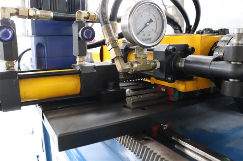
Hüdraulikõli temperatuuri muutused: Pideva töö käigus tõuseb toru paindemasina hüdraulikõli temperatuur, mis põhjustab süsteemirõhu ja reageerimiskiiruse muutusi ning mõjutab paindemääramatust.
Mooduli löövmine lahti: Pikaajalise vibratsiooni tõttu löövusid lahti mooduli kinnituskruvid, mis põhjustasid iga painde ajal väikest liikumist mooduli asukohas.
Veaotsing ja parandusstrateegiad
Materjali kinnitamine: Veendu, et toru sort, seina paksus ja keevituskoht vastavad protsessinõuetele. Kõrgelt elastsete materjalide puhul mõõda tagasipöördumise kompensatsiooniväärtus uuesti.
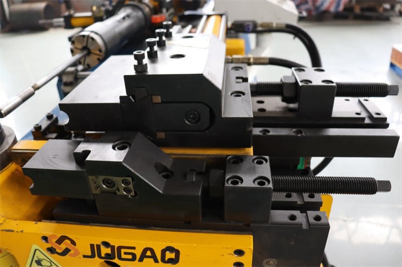
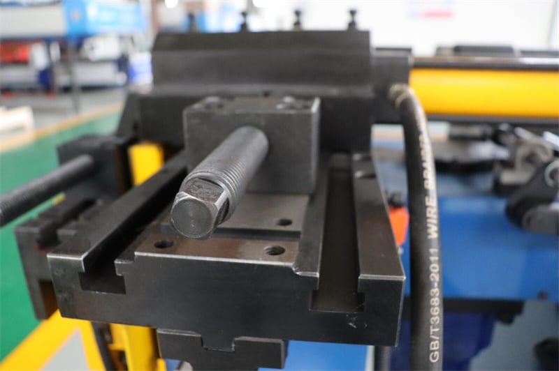
Mooduli kontroll: Veendu, et paindemooduli, kinnitamismooduli, kortsude ennetamise mooduli ja südamiku mudelid vastavad praegusele toru läbimõõdule ja painderaadiusele. Kontrolli nende kulutust ja paigaldustihedust.
Seadme kalibreerimine: kalibreerige regulaarselt paindemisnurga, toitelänga ja pöördenurga tegelikke väärtusi, et tagada nende kooskõla näidatavate väärtustega. Kontrollige kodeerija ja läheduslülite õiget tööd.
Programmi kontroll: veenduge, et kõik programmis olevad parameetrid (paindemiskiirus, kinnitumisjõud, südamiku asukoht, paindemisnurk) vastavad tegelikele töötingimustele.
Esimase detaili kontroll: iga toru läbimõõdu, seina paksuse või vormi muutumisel tuleb teha esimase detaili proovipainde ja täielik mõõtmete kontroll. Massitootmine võib alata ainult siis, kui esimane detail läbib inspektsiooni.
Protsessi andmed: koostage protsessiparameetrite salvestusleht erinevate materjalide ja spetsifikatsioonide jaoks edukate parameetrite arhiveerimiseks, et vähendada korduvat seadistusajat.
Lõpetatud painutatud toru ja ootustega tekkinud erinevus on põhimõtteliselt märk protsessisüsteemi tasakaalustamatusest. Materjalidest kuni vormideni, programmist kuni seadmete olekuni võib iga link olla kõrvalekaldumise allikas. Ainult süstemaatilise veaparanduslähenemisega, iga punkti ükshaaval kontrollimisega ning standardiseeritud esimese detaili kinnitamise ja protsessi salvestussüsteemi loomisega saab painutatud torude kvaliteeti hoida stabiilses ja usaldusväärsses vahemikus.

