


DELEM DA-66T CNC Bending Machine Installation Guide
Proper installation of the DELEM DA-66T CNC controller is critical toensuring the long-term performance and accuracy of your press brake. If you'repreparing to install this advanced control system, following a structured andprecise process is essential. This guide provides a clear, step-by-stepwalkthrough to help you complete the installation smoothly and avoid commonsetup pitfalls.
The DELEM DA-66T installation manual is designed with clarity in mind,offering straightforward instructions tailored to support a successfulintegration with your press brake. By adhering to these guidelines, you canensure that your system is configured correctly from the start, enablingreliable and precise operation from day one.
Let’s walk through the essential stages of the installation process to helpyou get your DELEM DA-66T up and running efficiently and accurately.
Preface
This document provides the technical information required for the properinstallation of a DA-Touch control system on a press brake. It is intended foruse by qualified service personnel authorized to perform machine installationand setup.
Limited guarantee
● The equipment is supplied by Delem without safety features. The machinemanufacturer has to ensure a safe environment.
● This equipment must be installed and used in accordance with Delem’sspecifications. The guarantee on the equipment is invalidated in the event ofimproper installation and/or use of this equipment.
● The General Terms and Conditions of Delivery of Delem shall apply to thisproduct. These conditions are available from Delem on request.
● This manual does not entitle you to any rights. Delem reserves the right tochange this manual without prior warning.
● All rights reserved. The copyright is held by Delem. No part of thispublication may be copied or reproduced without written permission from DelemBV.
Part I – Hardware description
This section contains the hardware specifications of a Delem control of theDA-Touch series.
⒈Introduction
This manual contains information necessary for installation of a DA-Touchcontrol. Such a control is the heart of a pressbrake control system with which asynchronised pressbrake machine is controlled.
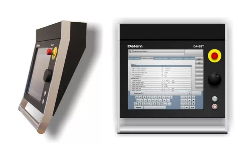
A DA-Touch control combines different tasks in one unit:
– programming products and tools;
– axis control during bending;
– adjustment of machine settings.
Product programming and control operation is described in the user manual[4,5] of the relevant control model. Pressbrake control and system I/O betweenthe control and the machine is carried out with
the help of the DM modules. This is explained in chapter 2 of thissection.
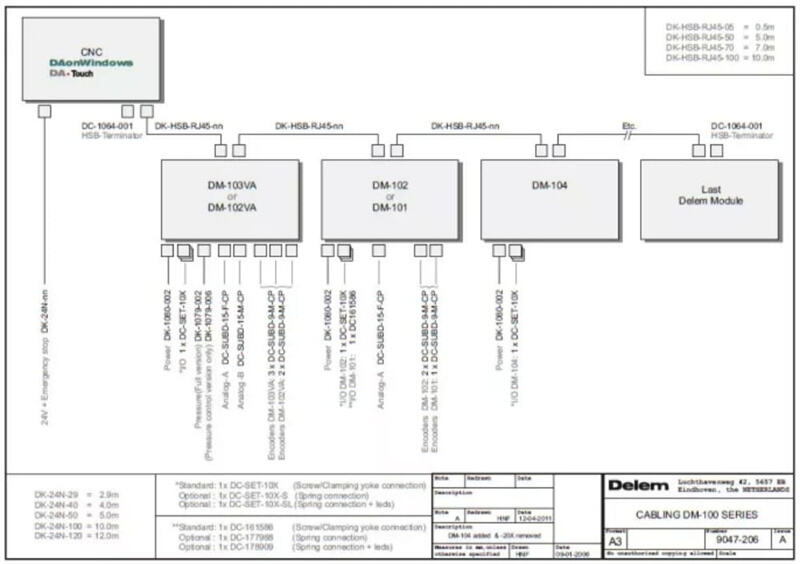
⒉System I/O
The system I/O between the DA-Touch control and the machine is carried out bythe DM modules. These modules are connected to the DA-Touch control by means ofthe High Speed Bus (HSB). The meaning of all I/O signals is described in themachine parameter
manual of the Delem controls.
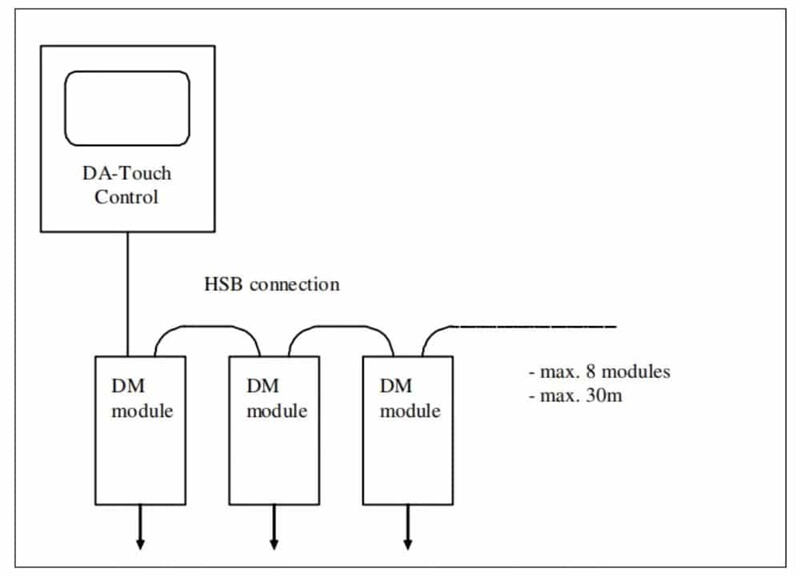
The maximum allowed number of modules for the HSB is 8. The total length ofHSB cable on the bus may not be longer than 30 metres. If more modules arerequired on the system then a second, optional HSB link can be enabled through asoftware option.
Before a module can be used to control an axis, it must be connected to thecontrol and be recognised as a valid DM module. The procedure to install DMmodules in the system and assign axes to those modules is described in themachine parameter manual of the Delem controls [1].
Specifications of all the DM modules can be found in the Delem modusys manual[2].
⒊ Specifications
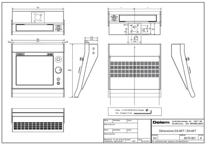
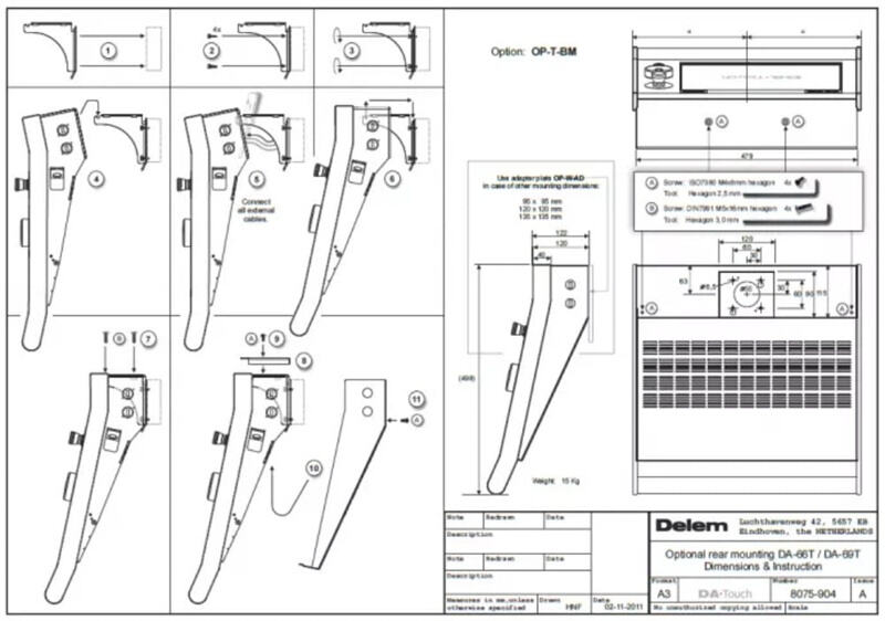
3.1 Physical dimensions
For the dimensions of the DA-Touch control, see the included drawings at theend of this section.
The following environment specification values are valid for every DA-Touchcontrol:
Ambienttemperature |
0– 50°C Warning:Avoid long-term exposure of the control to direct sunlight.Otherwise, the temperature inside the control will rise above tolerancelevels. Operation of the control should be carried out indoors. |
Storagetemperature |
min.-10°C max. 70°C |
Relativehumidity |
max.90 % non-condensing |
EMC |
designedand built to meet the following standards: • EN50081-2 •EN61000-6-2 |
Enclosure |
Designedand built to meet the requirements for IP54 standard. |
3.2Technical specifications
Powersupply |
18– 28 VDC 75W |
Display |
LCD/TFT 1280x 1024 Fault tolerance: – total of 15 pixels defect – max. 4 pixels defectwithin 10 mm radius – max. 10 non-white pixels in white screen – max. 10non-black pixels in black screen |
Interfaces |
2x HSB 2 x RS-232 2 x USB 1 x 10/100 baseT |
diskdrive(s) |
CompactFlashcard, 1GB (DA-66T) or 2GB (DA-69T) |
emergencystop button |
Ratedinsulation voltage: 250 V AC/DC Rated peak voltage Uimp: 2.5 kV Rated operatingcurrent Ie: • AC 15 B300 3A / 120V, 1.5A / 240V; Ithe : 5A • DC 13 Q 300 0.55A /120V, 0.27A / 240V; Ithe : 2.5A Degree of pollution: 3 Positive opening travel:> 3 mm Actuation speed: 5 … 1000 mm / s Class of protection: II |
⒋Spare parts
4.1 Introduction
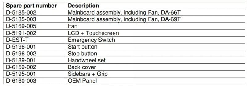
The table on the next page gives an overview of the available spare parts forthe DA-Touch controls. The next chapter contains an exploded view of a DA-Touchcontrol, in which the same spare part numbers are used.
Note:
When ordering spare parts, always mention control type, model number andserial number of the control for which the spare parts are meant.
4.2Spare parts overview
⒌Schematics
5.1 DA-Touch info
5.2 Miscellaneous
Part II – Machine settings
This section will describe the necessary settings of a DA-Touch controlregarding machine settings.
A lot of machine settings can be modified through the Windows environment.Windows operation should be done by an authorised person, who knows how tooperate Windows.
⒈The machine parameters
The adjustment of machine parameters and axis parameters is done in the Delemapplication. This procedure is described in detail in the Delem machineparameter manual [1].
Note:
Installation of options is not done within the Delem machine parameters menu.See chapter 3 for more information about option installation.
Note:
The software update procedure is not done within the Delem machine parametersmenu. See chapter 2 of this part for more information about the updateprocedure.
⒉Windows tasks
2.1Windows introduction
To access Windows function in a DA-Touch controller, a keyboard and mouseshould be connected to a USB port. To open the Windows start menu, press theWindows button on the USB keyboard.
To switch to windows without opening any application, click on the pencilsymbol in the lower right corner of the screen. The Delem control application isswitched to the background, but remains active.
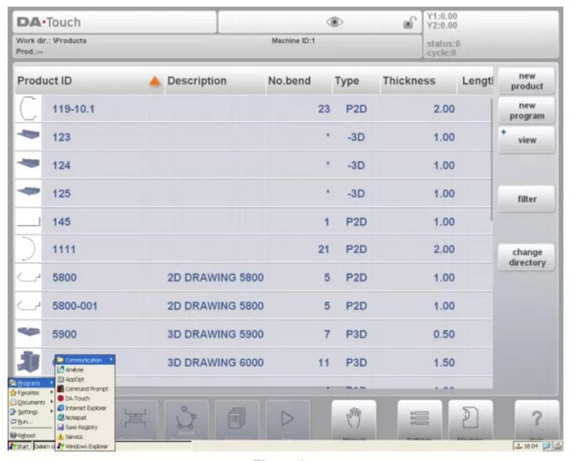
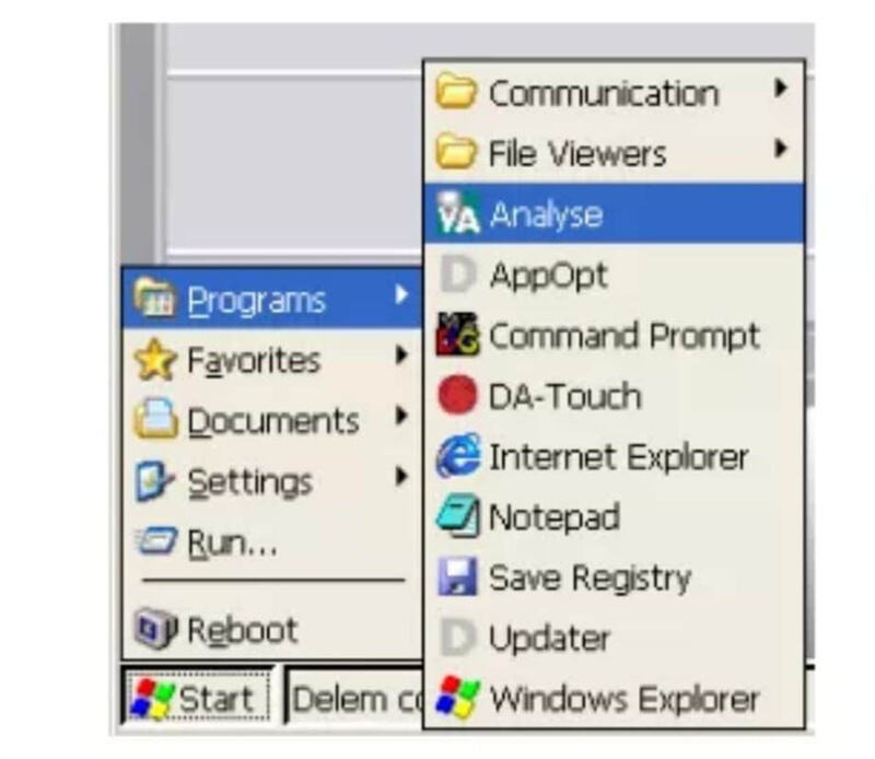
To activate a certain application, click on the Start button in the lowerleft corner of the screen. Choose an application from the list. For many of themachine tasks this procedure will be necessary, so be sure to familiariseyourself with this routine.
The ‘Reboot’ command right above the Start button serves to restart thecontrol. It will be indicated in this manual when this is necessary.
2.2 Log-in
For several operations and functions in the Windows environment it isnesecary to log-in first with the correct access level. If not logged in withthe appropriate level the function will not be carried out or an error messagewill appear.
The actual acces level will be indicated neer the key lock symbol
• After a restart/reboot of the control the access level will still beactive.
• The access level is reset when the control is switched off.
• The mentioned access codes are the same codes as for access to the machineparameters menu.
2.3 Directory structure
The data on the control has been organised into drives and directories, likeon a computer. Within the graphical interface of Windows, the term ‘Folder’ isalso used for a directory.
Most directories on the Windows desktop are volatile directories, which meansthey are lost when the control is shut off and are re-created when the controlis started. The following drives are permanent, because it refers to theCompactFlash card of the control:
Delem
Configuration
User
This CompactFlash card is the internal storage device of the control. Anydata that should be saved for later use should be stored in one of the drivesthat are located on the CompactFlash.
2.4 Important files
A lot of control settings are stored in files, which are located on the harddisk of the control. This is the case for the Delem application as well as forthe Windows platform. Whenever the control is (re)started, the software willsearch for these files and retrieve the last saved settings.
If for any reason the settings are mixed up, it is possible to delete thesefiles. At the next start-up, the control will assume its default settings. Thisshould only be done as a last remedy, if the control does not function properlyanymore.
If the settings are correct and you do not wish unauthorised people to changethem, it is possible to set these files as read-only files. This way settingscannot be changed. To set the file to read-only, proceed as follows:
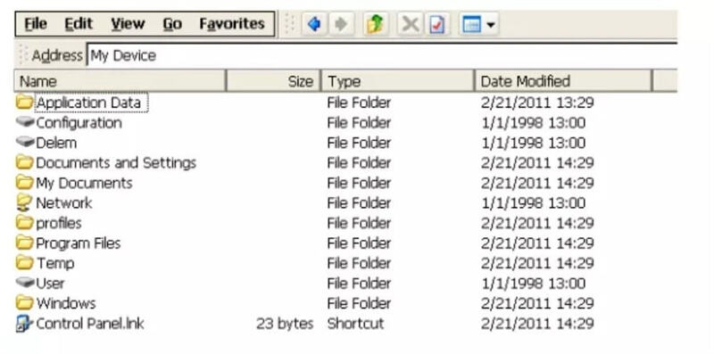
• open the Windows Explorer
• browse to the correct location (directory) to find the file
• click on the desired file
• open the File menu and select ‘properties’
A window like the one shown below should appear:
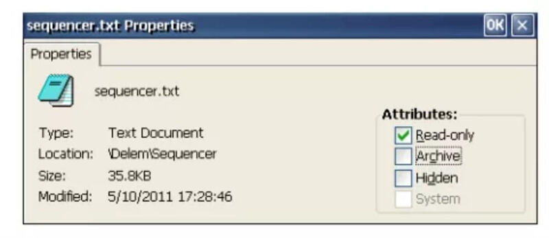
In the ‘attributes’ section of the window, mark the setting ‘Read-only’ andclick on ‘OK’ to save the setting. The file cannot be altered anymore.
In the example above, the properties of the sequencer file are shown. Thismeans that changes made in the sequencerfile will be ignored.
Another possibility is to mark files as ‘hidden’. A hidden file is not shownin the Windows Explorer and as such it is protected against unauthorised useractions. A hidden file can also not be opened from within Windows applications,such as Wordpad.The Delem application can still open a necessary settings file,even though it is hidden.
If an authorised person wishes to access hidden files, the Windows Explorerhas the setting to view all files. From within the Explorer, open the View menuand select ‘Options…’. The following window appears:
Do not show hidden files and folders
The file Explorer will not show files that have been marked as hidden.
Hide protected operating system files
The Explorer will not show files that are used by the Windows Operatingsystem.
Hide file extensions
The Explorer will not show the three-digit extension in file names.
On the following pages a list of files is given that contain settings for theWindows Operating
system and for the Delem control application.
2.5Windows Registry
Within the Windows OS, several control settings can be adjusted, such mousesensitivity, etc. Normally, these Windows settings are reset to factory defaultswhen the control is restarted or switched off.
If you wish to keep these settings permanently, it is possible to save thesesettings through the utility ‘SaveRegistry.exe’. This utility can be startedfrom the Windows start menu, Programs->Save Registry. All current settingswithin Windows are stored and will be retrieved on the next start-up.
The settings are stored in the file ‘user.reg’, which is located in thedirectory ‘\User\Delem\Boot’. When Save Registry is carried out while logged inwith level 1 or higher, the setting will be stored in ‘config.reg’ in thedirectory ‘\Configuration\Delem\Boot’. At start-up, both registry files arechecked and the settings from both files will be used (merged).
If for some reason the settings are not acceptable anymore then delete thisfile. On the next start-up the factory defaults will be restored.
Clearing the Registry can also be carried out through the Rescue Procedure.See section 2.10 about the Rescue Procedure.
Note:
Not all settings of the Internet Explorer are saved in the registry. TheStart Page of the Explorer is saved in the registry. Favourite websiteaddresses, however, are saved in the directory \Windows\Favorites. Thisdirectory is lost after power-down. To save these settings
you should copy the files in this directory to the control hard disk. Afterstart-up, these files can be copied back to the directory ‘Favorites’.
Files can be copied automatically after start-up by modifying the file‘autoexec.bat’. See section 2.9 about this file.
2.6 The Notepad program
The program Notepad can be used to edit plain textfiles on the control. Theprogram can be activated through the Windows Start menu:
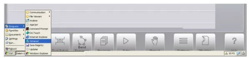
Another possible method is to open a suitable file by double-clicking on itwith the mouse. A file is suitable if it has a notepad icon.
2.7Networking
2.7.1Configuration
With the network functionality, the Delem application is able to copy orretrieve files to or from a network. The available network locations for theDelem application must be arranged on the Windows platform.
The procedure for offering a network takes roughly four steps:
1. establish network for the Windows platform
2. define network paths for Windows
3. check the network availability on the control
4. save the settings (registry)
Step one should be arranged by the network administrator. This involves allcommon tasks like connecting the control to a network, select the correctnetwork protocol for Windows and offer a shared drive.
Step two must be done on the control. Use the Windows Start menu to activatea command prompt. Type the following command:
2.7.2 Remove a network mapping
To remove an existing network mapping, perform the following steps:
Activate the command prompt and type the following command:
net use <path name> /d
2.7.3Network directory structure
When a network connection has been established, it is possible to store orretrieve data from a network.
2.8 Editing the autoexec.bat
The file ‘autoexec.bat’ is a standard file in the Windows system. Any commandthat can be executed from the command prompt, can also be put in this ‘batchfile’. Whenever the control is started or rebooted, the system will first lookfor the special batch file ‘autoexec.bat’. Any
command that is written down there will be executed by the systemautomatically.
Common tasks for such a file can be to connect to a network and copy files toor from the network. In the standard file, one task has been implemented:activate the Delem application. Other tasks can be added if required.
To edit this batch file, the control is equipped with the applicationNotepad. This program can be started from the Windows Start menu. You can alsoselect the file, open the File menu and select Edit.
⒊DA Control settings
3.1 Introduction
In this chapter some functions are discussed with which the functionality ofthe DA application is modified.
3.2 Add a KO-Table
A KO-table is a file containing initial Y-axis control parameter setting fora specific type of hydraulics. A default set of KO-tables is always included inthe software. In case a KO-table is needed that is not included yet, it can beadded manually.
Just copy the file (KO-7xxx.bin) to the following folder: \Configuration\Delem\Machine
The active KO-table can be selected in the machine parameters men (Generalparameters).
Note:
To be able to write, delete or modify files on the \Configuration drive youmust login with level 1 or higher.
3.3 Option installation
3.3.1Request option on the control
It is possible to install software options on the control. Options can berequested at Delem. Options for a DA-Touch control can be purchased at anymoment. It is done by buying an ‘Option Voucher’ for a specific function (3Dvisualisation, barcode reader etc.). A new option voucher is valid for anyDA-Touch control. Hence, it is possible to buyone or more option vouchers andkeep them in stock until the option becomes necessary on a control. An optionvoucher looks as follows:
3.1.2 Request option code at Delem
The UIR file that was generated by the option program must be send to Delem.From this UIR file a license file is generated. This license file can then beused to enable the option on the control.
There are different ways to send the UIR file to Delem. The simplest (andslowest) way is put the file on a floppy disk and send this floppy to Delem.After a certain period, you will receive a floppy disk with the licensefile.
Another method is to send the UIR file by e-mail to Delem and request theoption. You will receive a license file shortly.
The third method is to use an internet connection and connect to a specialDelem license
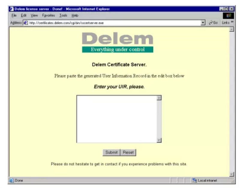
3.3.3 Delem Identification Module (DIM)
When an option is activated, it is stored in the Delem Identification module(DIM). The DIM is a small card that is inserted in the mainboard. The activatedoptions can be transferred to another control of the same type (DA-66T orDA-69T) by simply inserting the DIM in the new control.
3.3.4 Disable an option
Once an option is activated, it is registrated on the DIM. It is not possibleto remove an option from the DIM. If for some reason an option should be(temporary) switched off, it can be disabled with the AppOpt application.
To disable an option, select the option from the list and press the button“Disable license”.
3.4 Sequencer adjustment
The sequencer is the built-in PLC function of the Delem system. The text filewith sequencer code is stored on the hard disk of the control, in the filesequencer.txt. The default Delem sequencer is stored in the folder\Delem\Sequencer. This folder also contains the standard
sequencer include files, like delem.def.
3.5 Screen Colours
The control screens of the DA application can be modified to meet customer’swishes. This is carried out by modifying a file called ‘colours.ini’. Upondelivery, this file contains factory standard values. The default colours.inifile is located in the folder\Delem\Style\Default\1280×1024. To be able to editthe colour settings, perform the following steps:
• Login with level 1 or higher
• Create the sub-folder \Style\Default\1280×1024 in \Configuration\Delem
• Copy the default colours.ini file from \Delem\Style\Default\1280×1024to\Configuration\Delem\Style\Default\1280×1024
• Now colours.ini can be edited with a text editor, for example the built-inNotepad application.
3.6 Company logo
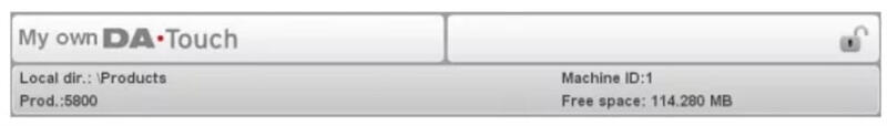
In the upper left corner of the control screen the Delem product logo‘DA-Touch’ is displayed.
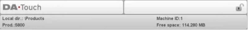
This logo is a small picture, which is stored on the control disk as astandard PNG image file: logo.png. If necessary, this logo can be replaced orchanged to the appropriate company logo:
3.7 Backup system / Restore system
It is possible to make a full backup of the DA-Touch control. This backupincludes:
– The application software
– All additional files on the \Configuration drive (sequencer etc.)
– Machine parameters
– All user data (products, tools, settings)
Make a system backup
Perform the following steps to make a full system backup:
• Insert a USB memory stick to one of the USB ports.
• Select the System Information page of the Machine menu.
• Press the softkey “backup system”. The following window appears:
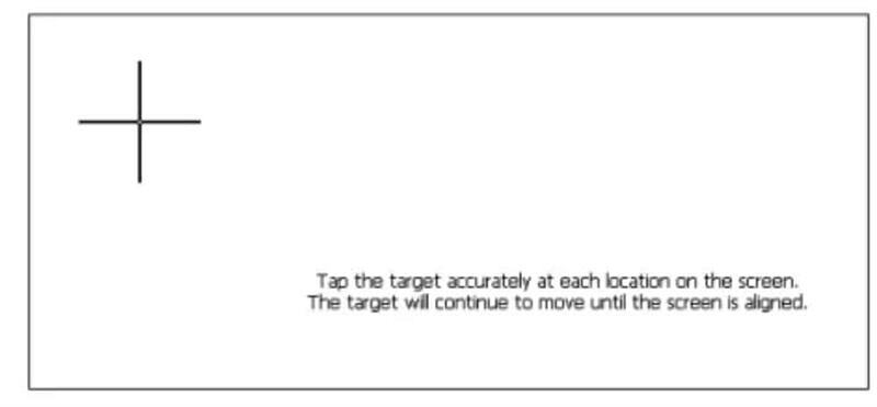
3.8 Touchscreen calibration
The Touchscreen is calibrated and ready for use upon delivery.
Sometimes, it may be necessary to recalibrate the Touchscreen, for exampleafter the control has been mounted on the machine. Calibration is carried outquick and easy.
• Select the Maintenance page in the Machine menu.
• Tap the button ‘calibrate touchscreen’.
• A white screen appears, with a black cross. Touch the black cross verycarefully.
• Repeat this every time the cross has moved to a new position.
3.9 Analysis program
The control is equipped with a program for analysis of a pressbrake cycle.This analysis program can run parallel to the DA application.
The working principle is as follows. During one bend cycle, the programrecords the values of a number of analog and digital I/O signals. All this datais immediately stored in a file on the control disk and can be representedgraphically.
First login with level 2 or higher.Then start Programs->Analyse from theWindows start menu to activate the analysis tool.
4. Update control software
4.1 DelemInstaller
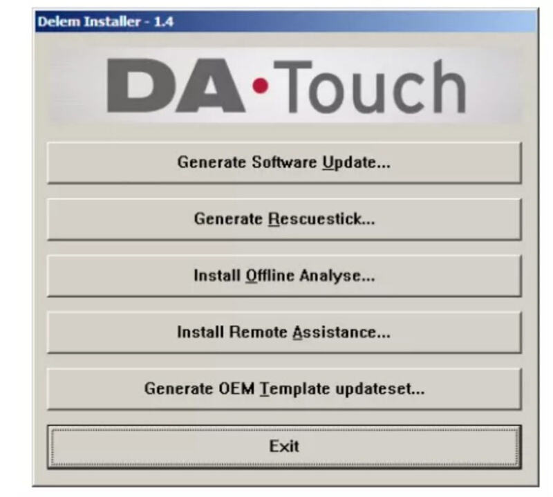
DelemInstaller.exe is a small program that runs on a PC. It is used togenerate an update file to be installed on a DA-Touch control.
Furthermore additional tools can be installed with DelemInstaller or a rescueUSB stick can be generated.
When DelemInstaller.exe is started on a PC, the following screen willappear:
4.2 Software update procedure
Note: The update procedure as described in this paragraph will only updatethe application software of a DA-Touch control. Modification made on the\Configuration drive and data on the \User drive will remain unaffected.
4.3 OEM update set
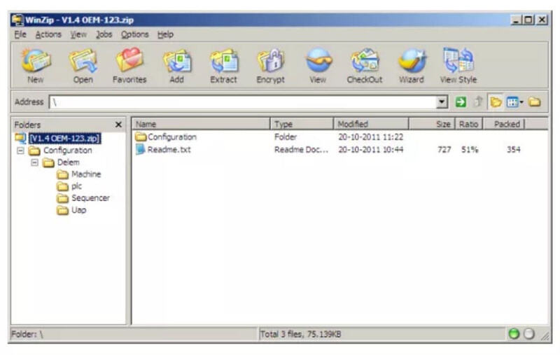
With the procedure as described in paragraph 4.2, only the standardapplication of the DATouch control will be updated. With an OEM update setadditional files, like a sequencer file, can be installed at the same time.
An OEM updare set is a .zip file containing the application software and theadditional files, organized in the same folder structure as they are installedon the DA-Touch control.
With the DelemInstaller application a template .zip can be generated that canbe used as a starting point to compose your own update set. This .zip filealready contains the most commonly used folders.
4.4 Control Rescue procedure
4.4.1 Introduction
The Rescue procedure for the Delem control is meant to re-install alloriginal software on the control. It is meant as a last resort, when otherattempts to ‘cure’ the control have failed and/or the control does no longerboot from the internal hard disk (the compactflash card).
When this procedure is carried out, all existing data on the hard drive iserased: products, tools, etc. The license codes for control options are noteerased. These options are not stored on the CompactFlash card but on theDIM.
This procedure can only be succesfull when all hardware is stillfunctional.
4.4.2 Requirements
To perform the procedure on the control, the following equipment isnecessary:
– a complete DA-Touch software set;
– a PC running the Windows operating system (Windows XP, Windows 7);
– a USB stick;
4.4.3 Rescue procedure
The rescue procedure is carried out with a USB stick, which is recognised bythe control as an external USB disk. The USB stick is equipped with thenecessary software and the control is booted from USB stick to re-install thecontrol software.
Part III – The diagnostic program
To be able to test a DA-Touch control, it has been equipped with a diagnosticprogram. With the test functions of the diagnostic program the service engineercan test the control itself and the communications to externally connectedsystem components.
Before starting the diagnostic program it is required to check if thehydraulic pump of the pressbrake is not running. This is because during thediagnostic operation of the control no regulation of the pressbeam isperformed.
⒈General remarks
1.1 Valve outputs
With the diagnostic program you have to be very careful because theproportional valves can be deflected. The high-retaining valves have to be inthe closed position in order to prevent the top beam coming down. It is goodpractice to place the top beam in its lowest position
before starting the diagnostic program.
1.2 Components check
In the description of the tests it is indicated which component(s) is(are)responsible for correct functioning of that particular part.
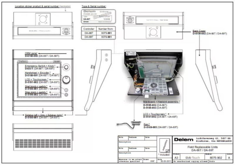
See for exploded view drawing with all internal cables and cards of theDA-Touch controls the included diagrams at the end of part I.
The mainboard assembly of the control can be exchanged easily, since allspecific data is stored on the hard disk.
If the internal hard disk (the CompactFlash card) must be replaced, it isrecommended to make a back-up of all user-specific data: products, tools,program constants and machine parameters. Use the ‘product backup’ and ‘toolsbackup’ tools in the Setting menu for this
purpose. Together with the tools automatically the parameters from theSettings and Machine menu (entered by the user) will be written to the backupmedium. To save the machine parameters, you have to go the machine parametersmenu and and select option 5, Parameter backup.
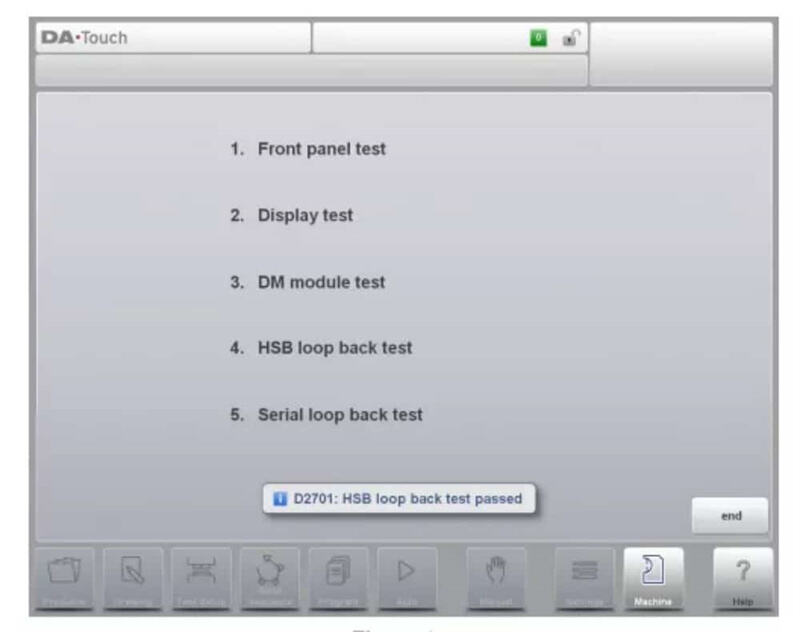
⒉Test-menu
When the diagnostic program has been started the screen shows the menu asindicated in figure 2.a (example of diagnostic main menu).
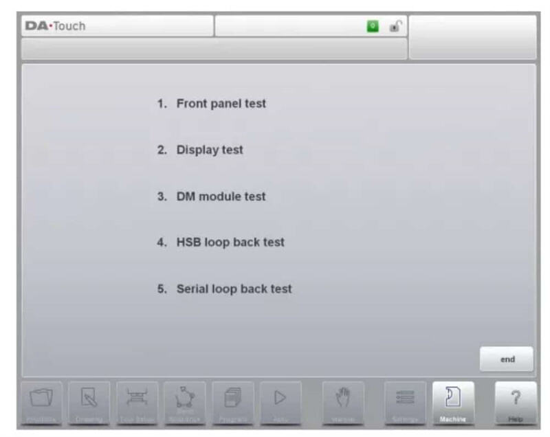
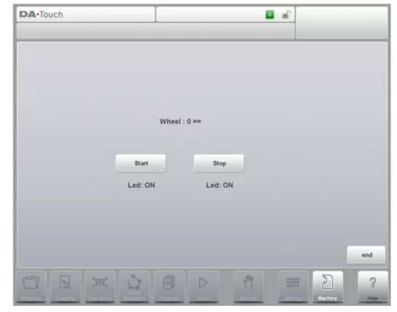
⒊Front panel test
Function
This test is meant to check the functioning of the start and stop button andthe handwheel.
Description
The follwing screen appears, like in figure 3.a.
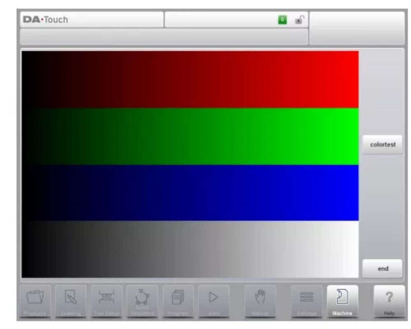
⒋Screen test
Function
To get a good idea about the colour setting and correct functioning of thecolour screen you will see a number of horizontal bars. It is important that the3 main colours are available (red, green and blue).
By tapping the button “colortest” a white screen will be displayed (togglefunction).
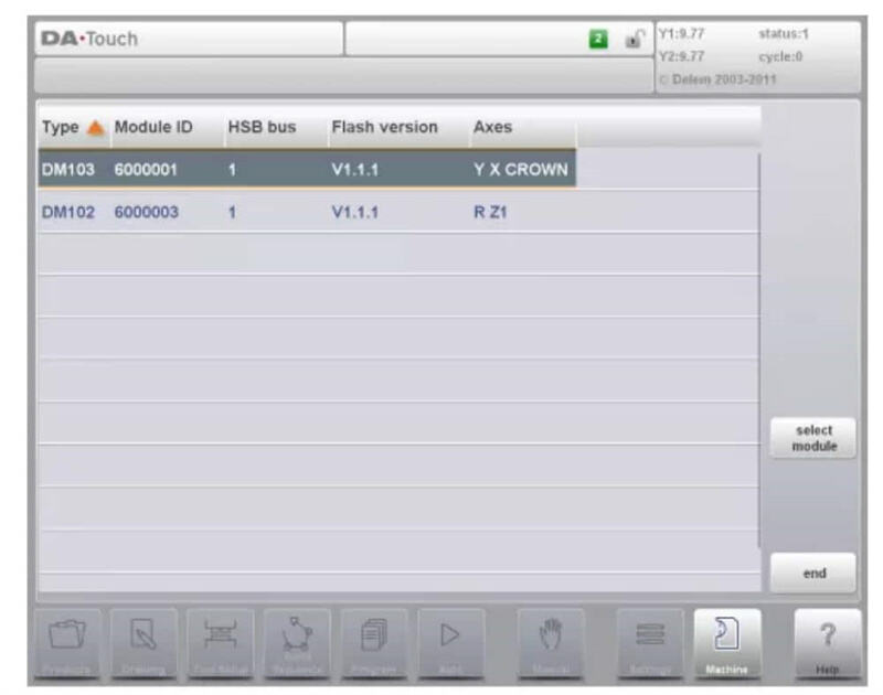
⒌ DM module test
Function
This test checks the inputs and outputs of the connected DM modules.
⒍Test of HSB
Function
With this test the High Speed Bus (HSB) connector of the control is checked.Description
With this test the HSB circuitry of the control is checked. To perform thistest:
• open the control;
• remove the standard HSB cable that is connected to the mainboard;
• take a small HSB cable and put one end on the first HSB connector and putthe other end on the second HSB connector;
• close the control;
• activate the control and go to the diagnostic main menu;
• Tap on item 4 in the main menu of the diagnostic mode.
⒎Test of the serial ports
Function
With this test the serial interface (RS-232) connectors of the control arechecked.
Description
• open the control;
• mount a loopback connector on the RS-232 port to test;
• close the control;
• activate the control and go to the diagnostic main menu;
• Tap on item 5 in the main menu of the diagnostic mode.
• Both connections are tested at the same time.
• The result will be displayed on the screen.
Important passwords
Level 0: 741 Level 1: 14753 Level 2: 32157 Level 3: 25789
If you want to download the DELEM DA-66T installation manual for your CNCpress brake in PDF, You can go to visit our download center, here you will findall the manuals you will need.You can also contact the JUGAO CNC MACHINEtechnical team.

