


Hvilke nøkkelfunksjoner kjennetegner DELEM DA-69T produkttilstand
Innholdsfortegnelse
• Introduksjon
○ Hovedvisningen
○ Produktvalg
○ Nytt produkt: Starte et nytt grafisk produkt
○ Nytt program: Starte et numerisk program
○ Filtrefunksjon
○ Endre mappe
○ Valg av nettverksprodukt
• Administrere produkter: Redigere, kopiere, slette, gi nytt navn, flytte og låse/opplåse
• DXF-importalternativet
• Produkttegningers mål
• Bøyelinjer og lagvalg med linjetildeling
• Konvertering
• Konvertering av kantmål med informasjon om bøyetilligg
• DXF-innstillinger
• 3D-importfunksjonen (kun Profile-T3D Offline)
• Konvertering
• DXF-kontur-eksportalternativet
• Ofte stilte spørsmål (FAQ)
• Er DELEM DA-69T produktmodus enkel å integrere med eksisterende systemer?
• Hvordan forbedrer DELEM DA-69T produktmodus bøyepresisjonen?
• Konklusjon
I verden av avanserte bøyepresstyringssystemer, stikker DELEM DA-69T Produktmodus ut som en topplosning. Hvis du ønsker å få en klar forståelse av egenskapene som definerer denne produktmodus, har du kommet til rett sted.
I denne artikkelen vil vi gå nærmere inn på de grunnleggende egenskaper og funksjoner som gjør denne styringenheten til et foretrukket valg for presis metallbearbeiding. Uansett om målet er å optimalisere produksjonseffektiviteten eller forbedre bøyningsnøyaktighet, vil denne veiledning gi verdifulle innsikter i hvordan DELEM DA-69T kan dekke dine driftsmessige behov.
Introduksjon
DELEM DA-69T Produktmodus er utviklet for å optimalisere håndtering og produksjonsprosesser for bøyepresoperasjoner. I denne modus kan brukere enkelt velge eksisterende, tidligere produserte produkter eller programmer for å enten starte produksjon direkte eller foreta endringer for å utvikle lignende produkter. Denne fleksibiliteten er ideell for å effektivisere arbeidsflyt og sikre effektivitet i produksjonsprosesser.

Når det gjelder lansering av helt nye produkter eller programmer, tilbyr DELEM DA-69T Produktmodus praktiske funksjoner med alternativene «Nytt produkt» eller «Nytt program». Disse funksjonene gir operatører mulighet til å håndtere produksjonsoppgaver effektivt, med rask oppsett, tilpasning og gjennomføring—hvilket øker total produktivitet.
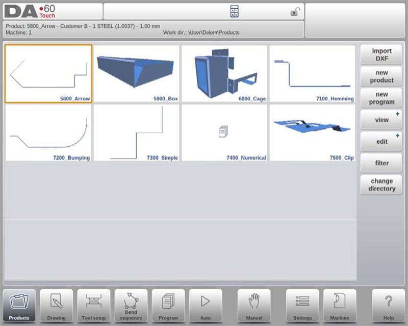
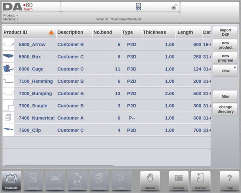
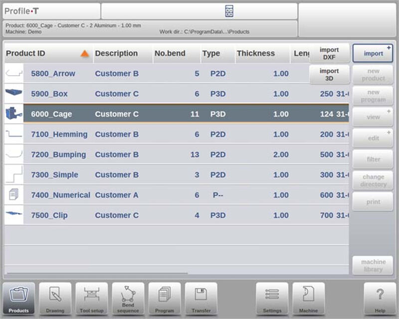
Hovedvisning
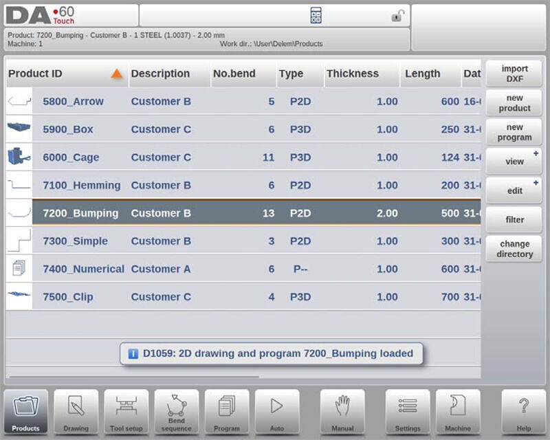
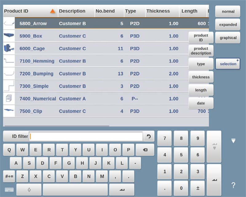
I DELEM DA-69T-produktmodus gir hovedvisningen en omfattende oversikt over programbiblioteket i kontrollsystemet. Dette intuitive grensesnittet lar brukere enkelt velge, laste og administrere produktprogrammer. Hvert element i produktlisten er representert med en miniatyrbilde – enten en grafisk illustrasjon for visuelle produkter eller et symbol for numeriske programmer – sammen med viktige detaljer som produkt-ID, produktbeskrivelse, antall bøyninger, produkttype og dato for siste bruk eller endring.
Produkttyper kategoriseres som følger:
• P: Produkt med CNC-program men uten tegning.
• -2D: Produkt med 2D-tegning men uten CNC-program.
• P2D: Produkt med både 2D-tegning og CNC-program.
• -3D: Produkt med 3D-tegning men uten CNC-program.
• P3D: Produkt med både 3D-tegning og CNC-program.
Hvis et produktprogram er aktivt, vises program-ID-en øverst på skjermen. For å laste et program, trykk bare på produktets ID eller noe annet sted på produktets oppføringslinje. Hvis produktbiblioteket er større enn det synlige skjermbildet, kan brukere enkelt dra listen oppover for å få tilgang til flere produkter. Ved å trykke én gang på ønsket produkt, velges det og aktiveres i kontrollsystemet, noe som forenkler arbeidsflyten i DELEM DA-69T-produktmodus.
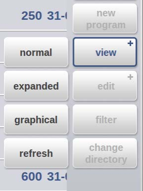
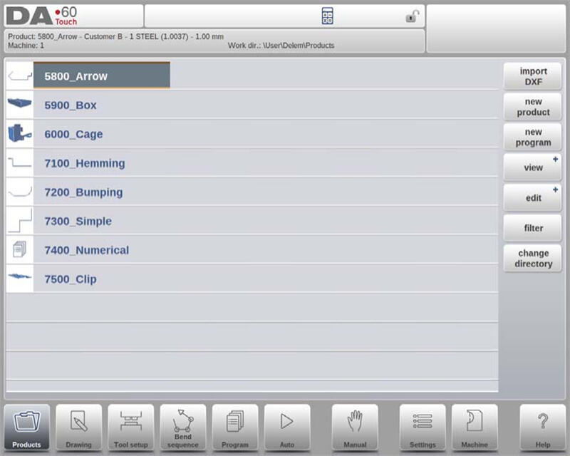
Synspunkter
For å vise produkter enten som en enkel liste eller i et helt grafisk format, kan Vis-funksjonen brukes. Ved å trykke på «Vis» kan brukere velge blant tre ulike visningsmoduser.
Produktutvalg
I DELEM DA-69T-produktmodus er produktvalg raskt og enkelt. Med ett enkelt trykk velges produktet og lastes inn i systemminnet, slik at produksjon umiddelbart kan startes ved å trykke på Auto-knappen. Brukere kan enkelt navigere gjennom produktets tegning, verktøyoppsett, bøyesekvens og numeriske program, noe som sikrer en strømlinjeformet og effektiv drift.
Nytt produkt: Start av et nytt grafisk produkt
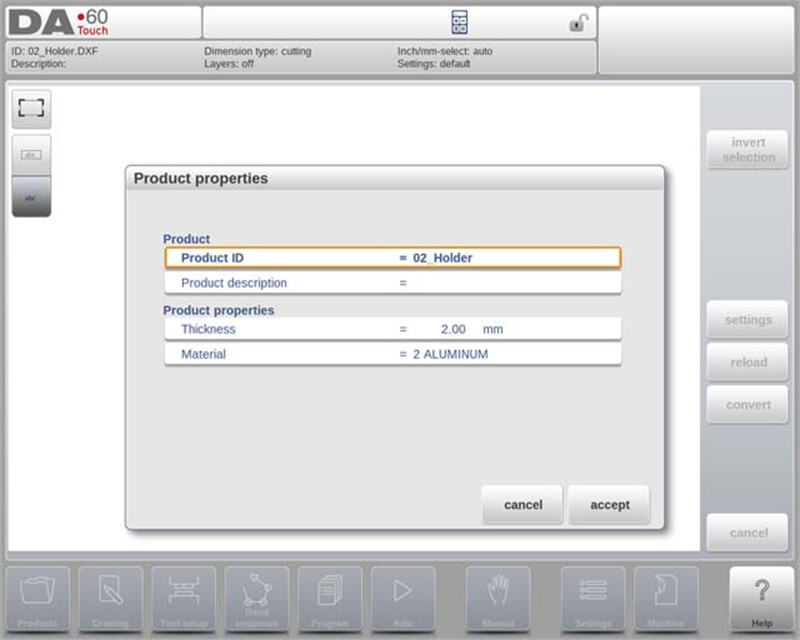
Å starte et nytt grafisk produkt i DELEM DA-69T-produktmodus er enkelt. Trykk bare på «Nytt produkt» for å gå videre til programmeringsfasen, der du starter med å skrive inn generelle opplysninger om det nye produktet. Viktige opplysninger som kreves inkluderer produkt-ID, tykkelse og materiale.
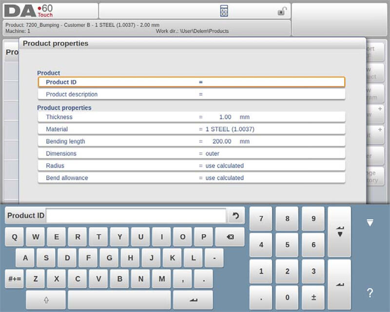
Disse opplysningene er avgjørende da de danner grunnlaget for nøyaktig programmering og produkttilpasning, og sikrer at alt samsvarer med dine spesifikke produksjonskrav.
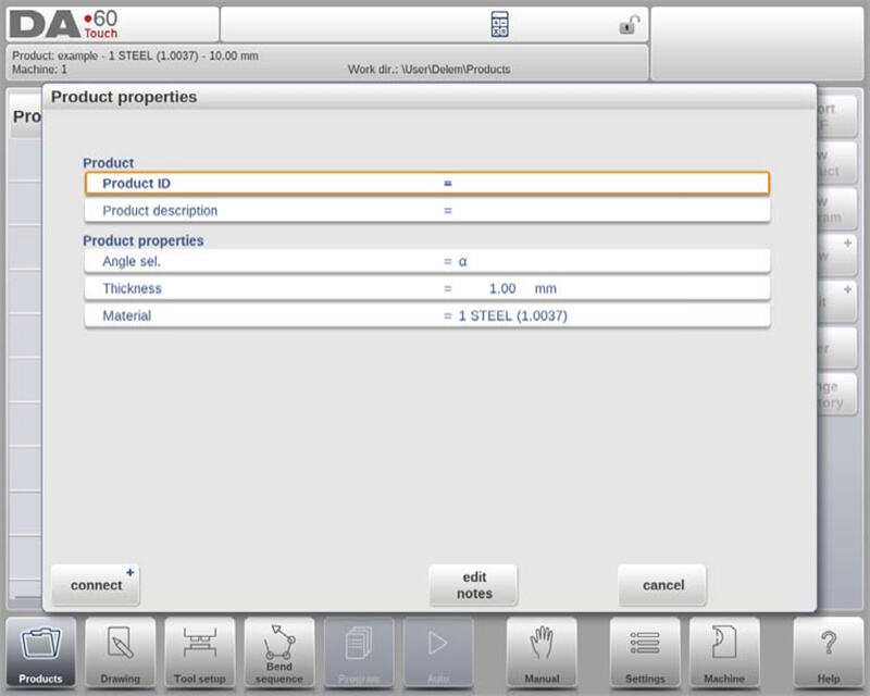
Nytt program: Start av et numerisk program
For å starte et numerisk program i DELEM DA-69T-produktmodus, trykker du på «Nytt program». Når du har valgt dette, skriver du inn generelle opplysninger som produkt-ID, tykkelse og materiale. Denne oppsettet lar deg begynne å programmere den første bøyningen, og gir nøyaktig kontroll og tilpasning for bøyeoperasjonene dine.
Filtreringsfunksjon
I DELEM DA-69T produktmodus forbedrer filterfunksjonen brukervennligheten ved å aktivere søk i sanntid for raskt å finne produkter. Ved å trykke på «Filter», kan brukere komme til filter-skjermen og skrive inn ønskede søkeord – inkludert Produkt-ID, Beskrivelse, Type, Tykkelse, Lengde eller Dato. Søk kan være delvise eller fullstendige, og systemet vil vise alle matchende resultater. Brukere kan også velge ulike visninger og spesifikke egenskaper for å ytterligere forfine resultater. Denne funksjonaliteten forenkler navigasjon og håndtering i produktmodus, og sikrer rask og effektiv tilgang til produktinformasjon.
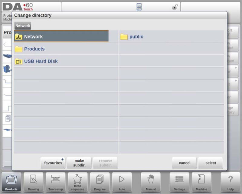
Endre mappe
DELEM DA-69T produktmodus gjør det enkelt å administrere produktkataloger. For å bytte eller legge til kataloger, trykk på «Endre katalog». For å fjerne en utdatert katalog, velg den og trykk på «Fjern katalog». Når du er i ønsket katalog, trykk på «Velg» for å gå tilbake til produktskjermen, som viser alle tilknyttede produkter. Navnet på gjeldende katalog vises i toppteksten for enkel oversikt.
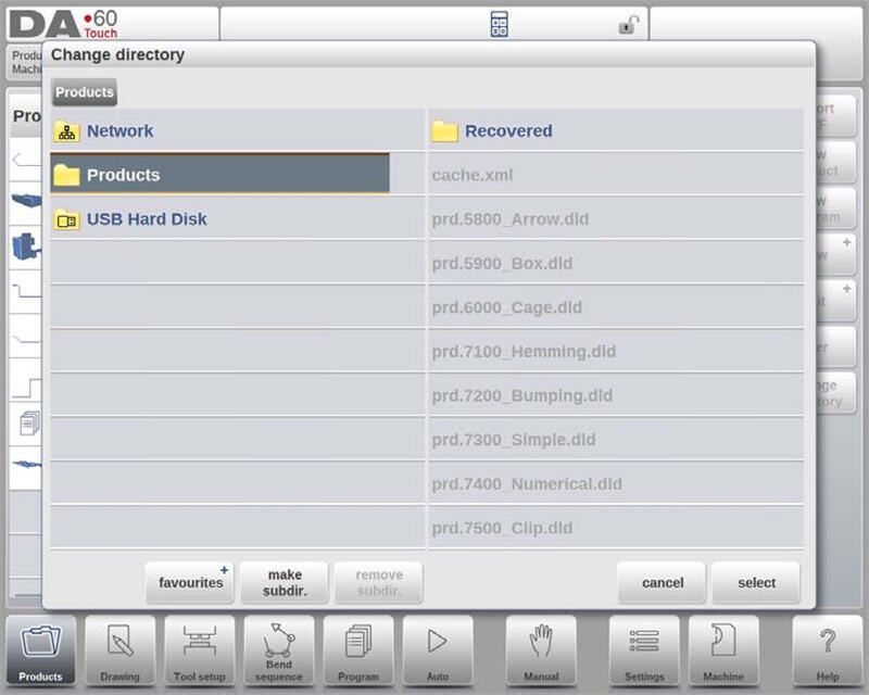
For å opprette en underkatalog, bruk alternativet «Opprett underkatalog» og skriv inn et navn med inntil 24 alfanumeriske tegn (unngå skråstrek ‘/’). For å slette en underkatalog må den være tom, og bekreftelsesmeldinger vises dersom det finnes filer eller underkataloger. Standardkatalogen «PRODUCTS» kan ikke slettes.
Selv om produktkopiering mellom underkataloger ikke er mulig i dette menyen, kan det gjøres i Tegning- eller Programmodus. Når man forlater produktvalgmenyen, beholdes den aktive underkatalog og produkt til et annet blir valgt. Denne effektive katalogforvaltning forbedrer organisering og produktivitet i DELEM DA-69T Produktmodus.
Nettverksproduktvalg
DELEM DA-69T Produktmodus forbedrer produktforvaltning gjennom integrering av nettverkskataloger. Når en nettverkskatalog er montert, vises den sammen med lokal Produkt-katalogen, og indikerer at den er klar for produktvalg og lagring.
Brukere kan enkelt navigere, velge, legge til eller fjerne kataloger via katalogleseren. Ved å velge en katalog returneres brukeren til Produkt-skjermen, som viser katalogens produkter. Den valgte nettverkskatalogen blir da den aktive lokale katalogen, og dens navn vises i skjermens topptekst.
Systemet beholder den aktive underkatalogen og produktet til et nytt valg gjøres. Hvis nettverkstilkoblingen avbrytes, lagres produktene i en "Gjenopprettet" underkatalog for å sikre datasikkerhet. Oppdateringsfunksjonen i Produktmodus oppdaterer produktbiblioteket på skjermen – spesielt nyttig når du jobber med nettverkslokasjoner. Denne integrasjonen forenkler operasjoner og øker arbeidsflyten i DELEM DA-69T Produktmodus.
Behandling av produkter: Rediger, kopier, slett, gi nytt navn, flytt og lås/ulås
DELEM DA-69T Produktmodus tilbyr robuste håndteringsfunksjoner som forenkler arbeidsflyten og øker produktiviteten. Disse brukervennlige funksjonene gir stor fleksibilitet i organisering og sikring av produkter og programmer. Her er en detaljert oversikt over hvordan de fungerer:
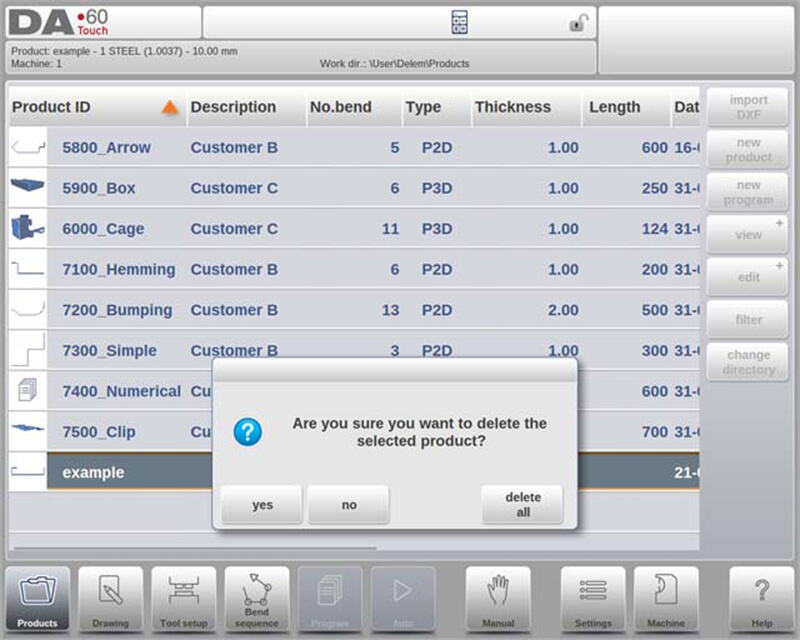
1. Slette produkter
○ For å slette ett enkelt produkt, velg det ved å trykke på det, trykk deretter på «Rediger» og velg «Slett». Bekreft handlingen for å fjerne produktet permanent.
○ For å slette alle produkter og programmer med én gang, bruk alternativet «Slett alle».
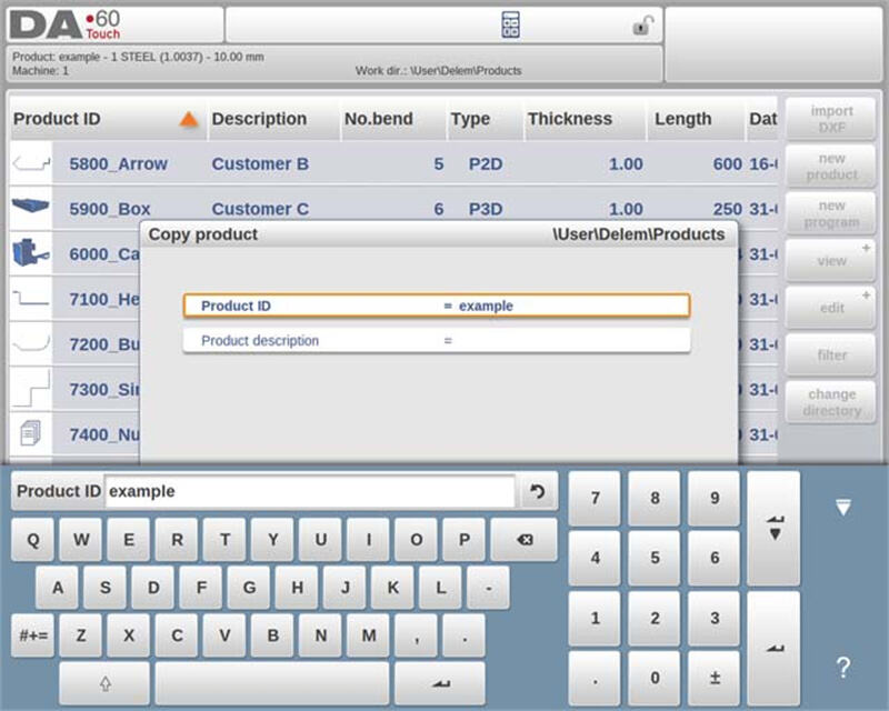
2. Kopiering av produkter
○ For å kopiere et produkt eller program, velg det, trykk på «Rediger», og velg «Kopier».
○ Deretter kan du gi produktet et nytt navn, og kopien vil bli opprettet. Den kopierte versjonen vil vises i samme katalog og beholde det opprinnelige verktøyoppsettet og bende sekvens (hvis tilgjengelig).
3. Flytting og omdøping av produkter
○ Produkter kan flyttes til en ny katalog eller omdøpt innenfor samme katalog i ett enkelt, sømløst trinn.
○ For å flytte eller omdøpe, velg produktet, trykk på «Rediger», og velg «Flytt» eller «Omdøp». For omdøping, skriv inn det nye navnet; for flytting, velg ny plassering. Begge handlinger beholder det opprinnelige verktøyoppsettet og bende sekvens.
4. Låsing og avlåsing av produkter
○ For å forhindre utilsiktede endringer i ferdige programmer eller produkter, bruk Lås/Avlås-funksjonen.
○ Gå til denne funksjonen via «Rediger», som lar deg slå av/på låsestatus for et hvilket som helst produkt eller program. Låste produkter forblir sikret og uendret med mindre de uttrykkelig låses opp.

Disse funksjonene sikrer at DELEM DA-69T Produktmodus ikke bare letter effektiv produktbehandling, men også beskytter verdifulle oppsett mot utilsiktede endringer. Denne fleksibiliteten og kontrollen bidrar til å opprettholde et jevnt og produktivt driftsmiljø.
DXF-importfunksjonen
DELEM DA-69T Produktmodus tilbyr en effektiv måte å integrere eksternt lagde design gjennom sin DXF-importfunksjonalitet. Denne funksjonen forenkler prosessen med å ta i bruk utdata fra CAD-systemer direkte i kontrollsystemet.
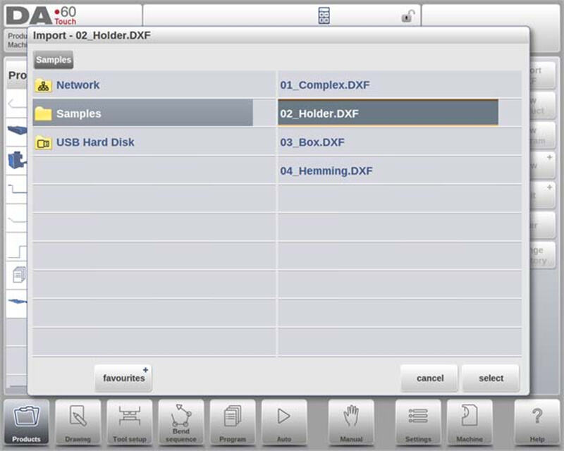
DXF-importprosessen
Start DXF-importen ved å klikke på kommandoknappen over «Nytt produkt». Dette åpner en filvelger der du kan velge en DXF-fil lagret på en USB-pinne eller i en nettverkskatalog.
Sikre nøyaktige importeringer
For optimale resultater, sørg for at din originale DXF-tegning er nøyaktig laget. Bøyelinjer bør koble seg til konturlinjer for å produsere en presis produkttegning. DXF-konverteren kan justere små unøyaktigheter hvis nødvendig.
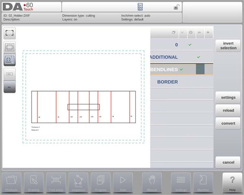
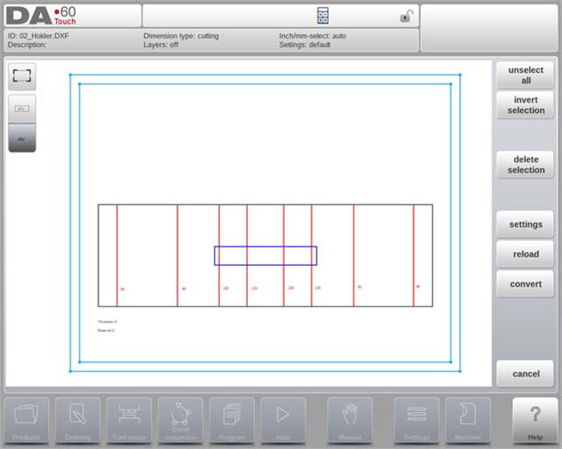
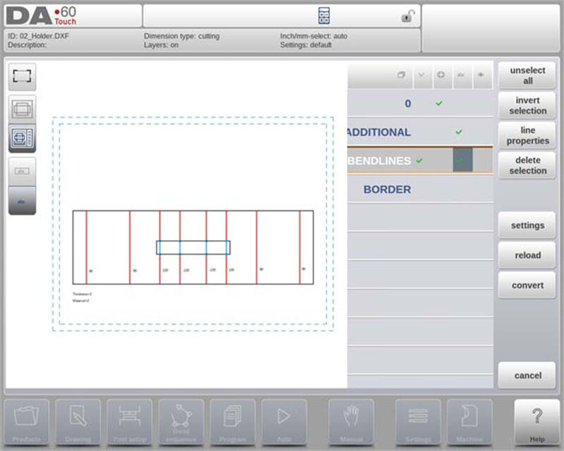
Visning av DXF-fil
Når en DXF-fil er valgt, åpnes importfunksjonsvinduet for å vise filen. Med lagvalg aktivert vises tegningen stiplet (indikerer at linjebetydning ikke er tildelt). Når lagvalg er deaktivert, vises filen med sine opprinnelige linjefarger.
Denne DXF-importfunksjonen i DELEM DA-69T Produktmodus forenkler bruk av detaljerte eksterne design, og øker dermed total produktivitet og designnøyaktighet.
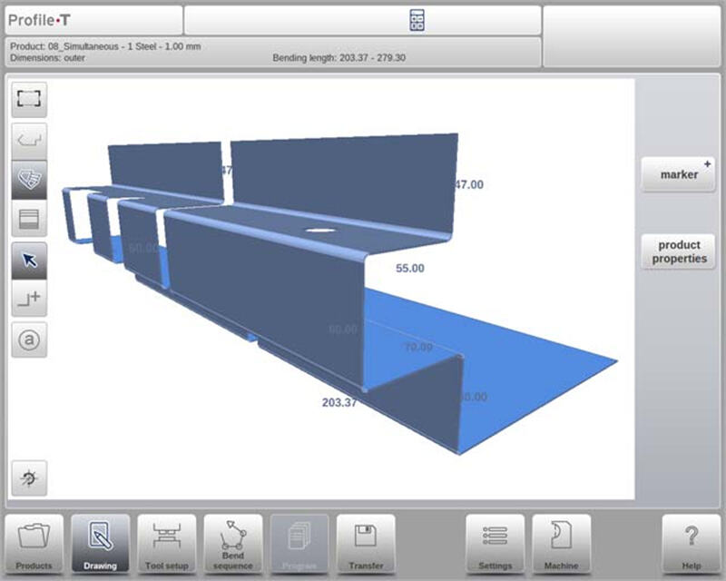
Produkttegning dimensjoner
DELEM DA-69T Produktmodus gir to hovedmetoder for organisering av tegningsfiler – avgjørende for nøyaktig produktferdigung:
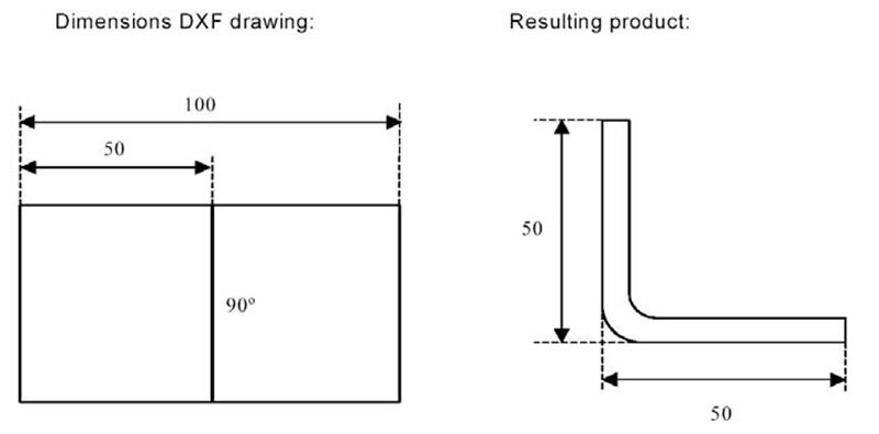
1. Prosjeksjonsmål
○ Denne metoden viser produktets sider og bøyelinjer i størrelsen på det ferdige produktet (ikke den faktiske platestørrelsen). Den tjener som en visuell referanse for organisering av platen i bøyer og overflater.
○ DXF-konverteren genererer en produkttegning som samsvarer med de opprinnelige designmålene. Ytterligere detaljer som materiale, platetykkelse og spesifikke mål angis senere for å veilede CNC-programmering for å oppnå det tenkte produktet. For eksempel kan et 100-enhetssegment resultere i et produkt med to 50-enheter-sider når man bruker yttermål.
2. Kappingsmål
○ Tegningen viser den faktiske kappede platetykkelse som brukes til bøying. Under konvertering er materialeegenskaper og platetykkelse kritisk, og bøyetillagsdata er nødvendig.
○ Konverteren bygger en 3D-produktegning ved hjelp av disse mål og en bøyetillagstabell. Det er avgjørende å bruke den samme tabellen for CNC-programmering for å sikre at det endelige produktet nøyaktig samsvarer med DXF-tegningen.
Disse metoder sikrer nøyaktig konvertering av design til fysiske produkter, noe som forbedrer funksjonaliteten av DELEM DA-69T Produktmodus i produksjonsmiljøer.
Bendelinjer og Lagvalg med Linjetildeling
DELEM DA-69T Produktmodus tilbyr en sofistikert tilnærming for håndtering og konvertering av DXF-filer—vesentlig for presisjon og effektivitet i bøyeoperasjoner. Under er nøkkelfunksjonene som definerer denne evnen:
1. DXF Linjetildeling
For å oppnå nøyaktig konvertering i DELEM DA-69T Produktmodus, er det avgjørende å tildele spesifikke produkt egenskaper til linjene i DXF-filen. Presisjonen i denne prosessen påvirker direkte kvaliteten på maskinens bøyeoperasjoner.
○ Tildeling lag for lag: Avhengig av innholdet i DXF-filen, kan bendelinjer, konturer og tilleggs tekstinformasjon tildeles lag for lag, noe som muliggjør en mer organisert og nøyaktig arbeidsflyt.
○ Automatisk deteksjon av bøyelinjer: Hvis lagvalg er deaktivert, kan systemet automatisk søke etter og identifisere bøyelinjer, noe som forenkler konverteringsprosessen.
2. Informasjon om bøyelinje
DELEM DA-69T produktmodus gir omfattende valgmuligheter for å definere informasjon om bøyelinjer gjennom tekstannotasjoner ved siden av linjene.
○ Vinkelinformasjon: Tekstetiketter kan definere vinkeldetaljer:
▪ Standard bøying: Normal luftbøying representert med positive eller negative verdier.
▪ Kanting: Angitt med en 'H' fulgt av for-bøye-vinkelveien.
▪ Radius: Vist med en 'R' fulgt av radiusverdien.
○ Flensretning: Positive verdier indikerer oppover bøying, mens negative verdier indikerer nedover bøying.
3. Produktinformasjonsstyring
I tillegg til produktutformingen kan en DXF-fil inneholde tilleggsinformasjon som produsentdetaljer, mål og produktbeskrivelser.
○ Lagfiltrering: Når disse detaljene er organisert i separate lag, kan brukere filtrere bort unødvendig informasjon ved å velge spesifikke lag for konvertering.
○ Innstillinger for lagvalg: Valg av lag kan slås av eller på via innstillingene på hovedskjermen, noe som påvirker hvordan lagegenskaper tildeles og vises.
4. Valgmuligheter for lag
Funksjonen for lagvalg i DELEM DA-69T produktmodus har stor betydning for hvordan linjer behandles:
○ Lagvalg på:
▪ Visuell representasjon: Viser alle tilgjengelige lag med symboler for vinkler, konturer og tekst.
▪ Avkrysningstilordning: Brukere kan tildele lag til spesifikke egenskaper (f.eks. bøyelinjer eller konturlinjer) via avkryssingsbokser.
▪ Fargekodet visualisering: Linjer vises i blått (konturlinjer), rødt (bøyelinjer) og svart (tilordnet tekst) for tydelig differensiering.
○ Lagvalg av:
▪ Automatisk tildeling: Kontrollsystemet håndterer automatisk linjeegenskaper og gir en enkel tilnærming for brukere som foretrekker minimal manuell justering.
5. Linjevalg og administrasjon
DELEM DA-69T-produktmodus tillater også detaljert valg og håndtering av linjer:
○ Valg ved tapping eller dra: Brukere kan velge enkelte linjer ved å trykke eller dra for å velge flere linjer.
○ Justering av egenskaper: Når linjer er valgt, kan de slettes eller deres egenskaper endres – spesielt når lagvalg er aktivert.
○ Inndeling av polylinjer: Funksjonen Del kan dele polylinjer i separate linjer for mer detaljert redigering.
Omvending
DELEM DA-69T-produktmodus tilbyr en effektiv prosess for konvertering og håndtering av DXF-tegninger og sikrer presisjon og tilpasning i produksjonsarbeidsflyten. Slik forbedrer denne funksjonen driftseffektiviteten:
Problemfri konverteringsprosess
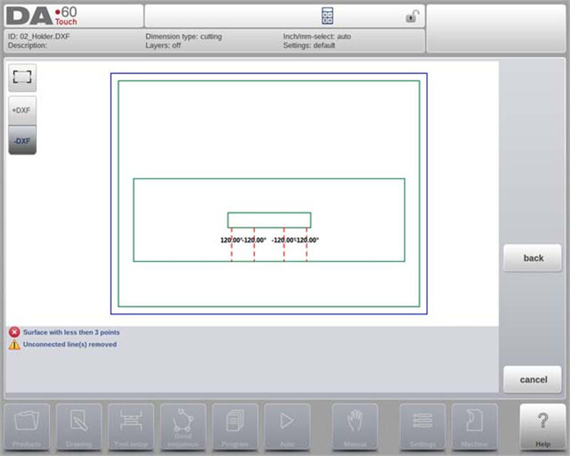
Når linjetildelinger er satt, trykk på "Konverter"-knappen for å starte konverteringen. En forhåndsvisning av konverteringen vises, med markering av eventuelle advarsler eller feil som krever oppmerksomhet. Under konvertering vises DXF-tegningen med linjer som representerer ulike elementer: konturlinjer, bøyelinjer og indre konturer.
Fargekoding forenkler rask identifisering av linjeegenskaper etter konvertering:
• Blå: Representerer konturlinjer (markerer produktets ytre grense).
• Rød: Indikerer bøyelinjer som kreves for produktet.
• Grønn: Angir indre konturlinjer (representerer produktets interne detaljer).
• Svart: Tekster som er tildelt vises i svart for bedre lesbarhet.
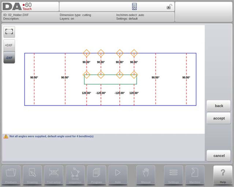
Eventuelle problemer under konvertering merkes med røde firkanter, og ytterligere advarsler eller informasjon vises nederst på skjermen.
Fullføre konvertering
For å fullføre konverteringen, trykk på «Aksepter». Hvis det er behov for revisjoner, bruk «Tilbake»-kommandoen for å gå tilbake til forrige trinnet. Etter akseptering vil de konverterte produkt egenskaper være synlige og åpne for endringer. Lukking av dette vinduet fullfører konverteringen, med resultatet vist i tegningsseksjonen.
Fortsetting av arbeidet etter konvertering
Etter konvertering, fortsett med verktøyoppsett og bestemmelse av bøyesekvens—på samme måte som for manuelt tegnede produkter. Denne systematiske tilnærmingen sikrer at produkter er klare for produksjon med presisjon og pålitelighet.
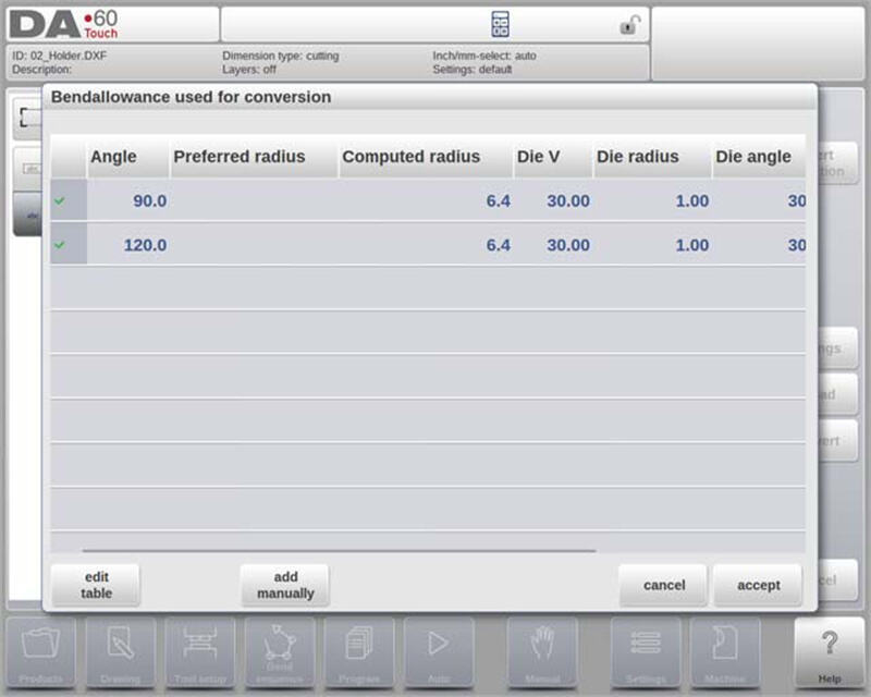
Konvertering av kappedimensjoner med bøyetillleggsinformasjon
DELEM DA-69T produktmodus er spesielt godt egnet til håndtering av bøyetilllegg når DXF-filer med kappedimensjoner blir konvertert. Denne funksjonen sikrer presisjon ved effektivt å bruke bøyetillleggstabellen:
• Konsekvent bruk av bøyetilllegg: Under konvertering gjenbruker systemet bøyetillag som ble brukt i utbrettet fase. Det refererer til kontrollens bøyetillagstabell og verifiserer at nødvendig data er tilgjengelig for alle bøyer, noe som sikrer nøyaktighet.
• Valg mellom flere oppføringer: Hvis det finnes flere sett med bøyetillag, kan operatøren velge det mest passende – hjulpet av foretrukket og beregnet radius. Hvis bare ett sett er tilgjengelig, vil dette bli brukt automatisk.
• Redigeringsmulighet: Hvis det ikke finnes noen eksisterende oppføring, kan bøyetillagstabellen oppdateres direkte fra popup-vinduet, slik at det er enkelt å legge til ny informasjon.
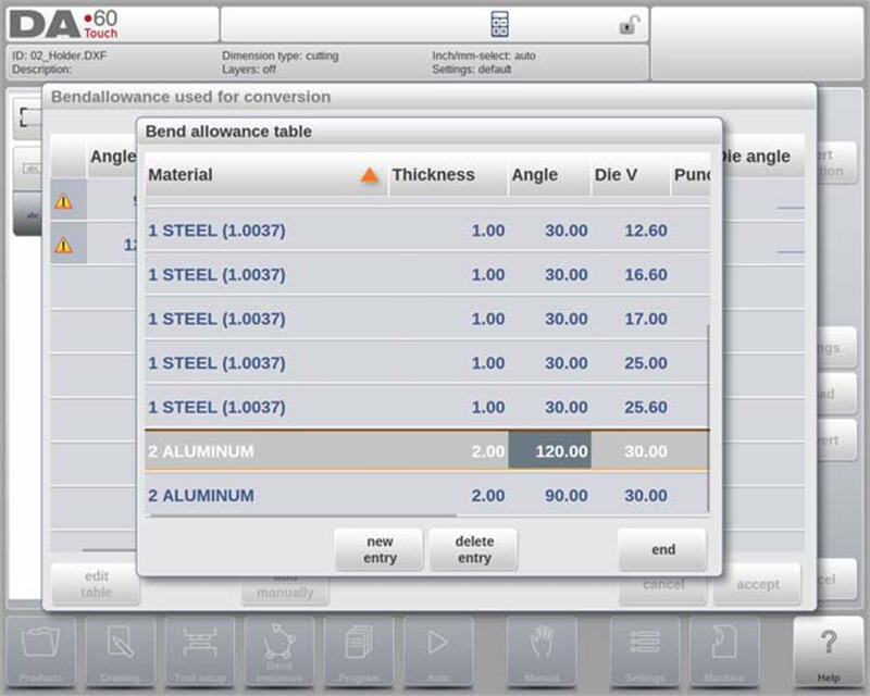
Legge til bøyetillag manuelt
DELEM DA-69T Produktmodus forenkler håndtering av bøyetillag og sikrer presise bøyeoperasjoner:
1. Manuell inntasting av bøyetillag: Bøyetillagsdata fra DXF-skjæremålstegninger kan tastes inn manuelt (hvis angitt), og dermed overstyre standardberegninger.
2. DXF-importering: Når en DXF-fil med inkluderte bøyetillatelsesverdier importeres, blir disse verdiene automatisk brukt på de angitte bøyene.
3. Håndtering av manglende data: Hvis informasjon om bøyetillatelse ikke er tilgjengelig fra tabellen, ber systemet brukeren å velge blant eksisterende oppføringer eller manuelt skrive inn data før konvertering.
4. Aktivering av bøyetillatelses-programmering: For å bruke manuelle bøyetillatelsesinnstillinger i Tegnings-funksjonen, må denne funksjonen aktiveres i produktets egenskaper. Aktiveringen skjer automatisk ved importering.
Disse funksjonene lar operatører kontrollere bøyning med presisjon og enkelhet.
DXF-innstillinger
I DXF-omformerens innstillinger kan konverteringsparametere konfigureres. Flere innstillingfiler kan lagres for spesifikke tegningstyper, med funksjoner for «Lagre som» og «Last».
Konverteringsparametere
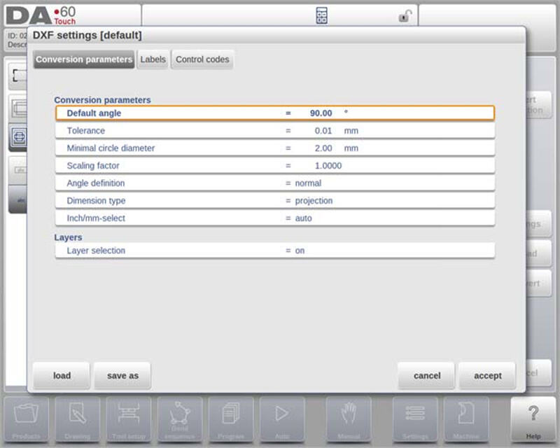
• Standardvinkel: Angi en standardvinkel for å konvertere bøyelinjer uten spesifisert vinkel.
• Toleranse: Definer en toleranse for automatisk tilkobling av ikke-tilknyttede linjer, slik at konvertering blir sømløs.
• Minste sirkeldiameter: Velg en minimumsdiameter for konvertering av sirkler (mindre sirkler vil bli hoppet over).
• Skaleringsfaktor: Bruk en faktor for å tilbakestille skalerte DXF-filer til deres reelle dimensjoner.
• Vinkel- og måldefinisjoner: Velg mellom normale og komplementvinkler, og velg projeksjons- eller kuttmål.
• Tomme/mm-valg: Bruk automatisk mm- eller tommeinnstillinger basert på kontrollsystemets konfigurasjon.
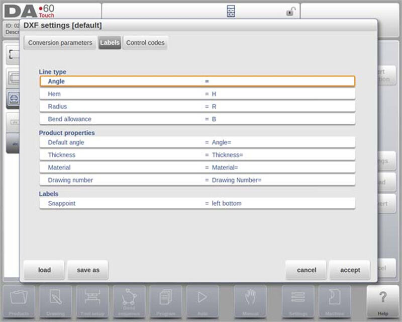
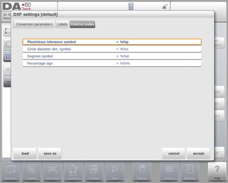
Avanserte funksjoner
• Lagvalg: Tilordne konverteringsegenskaper etter lag for økt presisjon.
• Etiketter og kontrollkoder: Konfigurer etiketter og kontrollkoder for å automatisere tildeling av egenskaper i DXF-filer.
• Kompatibilitet med DXF-filer: Konverteren leser ulike enheter (f.eks. Tekst, Linje, Polylinje) og støtter ECS-koordinater for 3D-tegninger når de er i X-Y-planet.
DELEM DA-69T Produktmodus har robuste funksjoner som forenkler DXF-filkonverteringsprosessen og øker nøyaktigheten og effektiviteten i metallbearbeidingsoperasjoner.
3D-importfunksjonen (kun Profile-T3D Offline)
Denne funksjonaliteten lar brukere importere .IGES- og .STEP-filer fra eksterne CAD-systemer, som et alternativ til manuell tegning.
Nøkkelpunkter for 3D-importfunksjonaliteten
• Støttede filtyper: Importerer generiske .IGES- og .STEP-filer, noe som sikrer kompatibilitet med ulike CAD-systemer.
• Starte importen: Start ved å klikke på knappen «Import» over «Nytt produkt», som åpner en filvalgsbrowser.
• Filtilgang: Velg filer fra en USB-minnepinne eller nettverkskatalog ved å bla gjennom til ønsket plassering.
• Visualisering og konvertering: Ettersom en fil er valgt, kan du vise den i 3D for vurdering før du starter konverteringen.
Konvertering: 3D-konverteringsprosessen
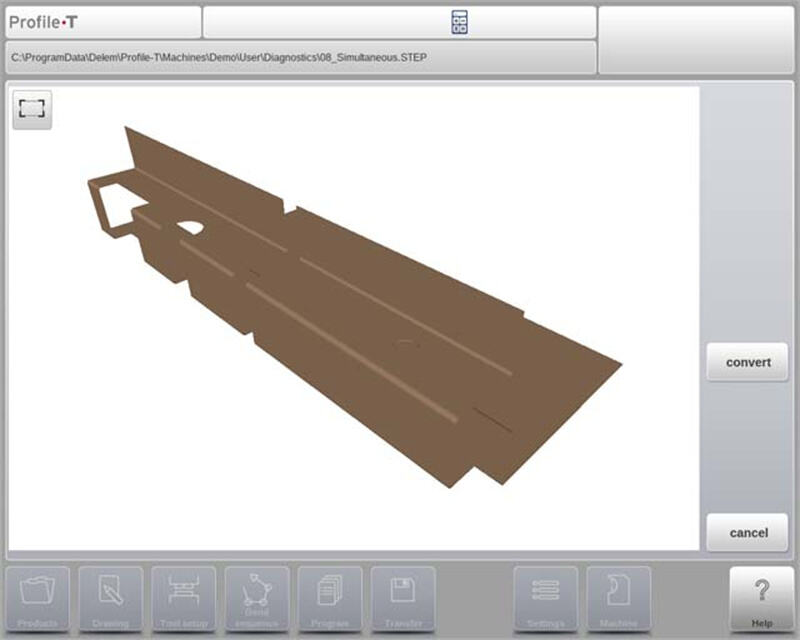
Trykk på «Konverter» for å starte konverteringen, som transformerer 3D-designet til et produkt med bøyelinjer og spesifikke plategenskaper. Produktet vises med sine bøyelinjer. Hvis ingen feil finnes, trykk på «Godta» for å fullføre og vise produktet i Tegnemodus.
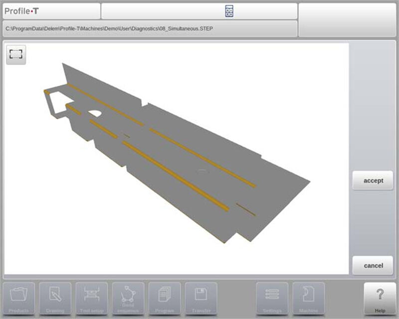
Etter konvertering fortsett med verktøyvalg og programmering av bøyesekvens for å sikre at produktet oppfyller spesifikasjonene.
krav til 3D CAD-filer
IGES- og .STEP-filer må følge spesifikke platekonstruksjonskrav gitt av Delem. Filer må være beregnet for sveisepressebehandling.
DXF-kontur-eksportvalg
Som del av DXF-funksjonaliteten, lar «Eksporter DXF»-funksjonen (tilgjengelig via «Rediger» i Produktmodus og «Overfør» i Profile-T) brukeren eksportere ethvert produkt – inkludert bøyeadskjøtninger – som en kontur. Denne konturen lagres som en DXF-fil som inneholder skjæremålene.
Vanlegaste spørsmål (FAQ)
Er DELEM DA-69T Produktmodus lett å integrere med eksisterende systemer?
Ja, DELEM DA-69T Product Mode har avanserte koblingsmuligheter som muliggjør sømløs integrasjon med eksisterende produksjonssystemer, og sikrer effektiv dataoverføring og systemkompatibilitet.
Hvordan forbedrer DELEM DA-69T Product Mode bøyingsnøyaktighet?
Produktmodus forbedrer bøyingsnøyaktighet gjennom sin 3D-programmering og simuleringsfunksjoner, sanntids-feiloppsporing og en robust materiedatabase. Disse funksjonene hjelper til med å minimere oppsettingsfeil og sikre nøyaktige bøyeoperasjoner.
Konklusjon
I denne artikkelen har vi sett nærmere på de definierende egenskapene til DELEM DA-69T Product Mode. Dette toppmoderne kontrollsystemet leverer ubestriden presisjon og fleksibilitet, og øker effektivt produktiviteten til bøyebanken din. Husk at å forstå dets funksjonalitet og implementere beste praksis kan betydelig forbedre driftseffektiviteten.
Sikring av riktig oppsett og regelmessig vedlikehold av utstyret ditt er avgjørende for å maksimere ytelsen og levetiden. Ved å følge retningslinjene som er diskutert, kan du redusere nedetid og øke produksjonseffektiviteten. For ytterligere hjelp, detaljert støtte eller spørsmål, ta gjerne kontakt med vårt team. I tillegg anbefaler vi at du utforsker vår nettside for relaterte dokumenter og innsikt som kan fordype din kunnskap om bresseteknologier.

