


DELEM DA53T/DA58T Z-ღერძის კონტროლერის ოპტიმალური ექსპლუატაციის ხელოვნური სახელმძღვანელო
DELEM DA53T/DA58T Z-ღერძის კონტროლერის ოპტიმალური ექსპლუატაციის ხელოვნური სახელმძღვანელო
DELEM DA53T/DA58T Z-ღერძის კონტროლერის არასწორი კონფიგურაცია შეიძლება საკმაოდ მკაცრად შეამციროს პრეს-ტარების ექსპლუატაციური ეფექტურობა. ეს სრულყოფილი სახელმძღვანელო მოიცავს Z-ღერძის კონტროლერის სწორი დაყენების და ექსპლუატაციის მეთოდების დეტალურ აღწერას, რათა დაეხმაროს ოპერატორებს მიაღწიონ სიმშვიდით და მაღალი სიზუსტით მომხდარი პრეს-ტარების ექსპლუატაციას მისი ძირეული ფუნქციებისა და კონფიგურაციის პროცესების სრულყოფილი გაგების საშუალებით.
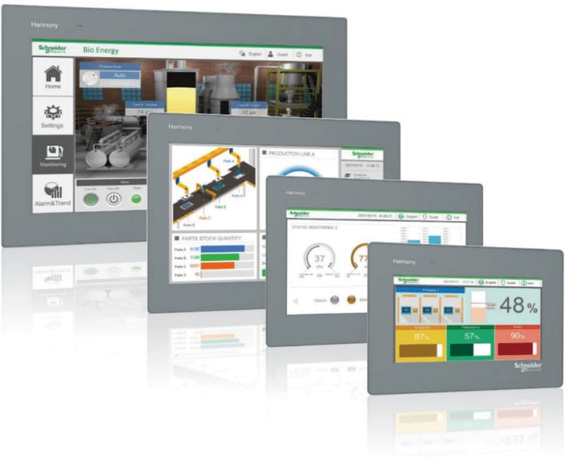
DELEM DA53T/DA58T Z-ღერძის კონტროლერი არის სპეციალურად შექმნილი კონტროლის კომპონენტი DELEM DA53T/DA58T CNC სისტემისთვის. იგი ინტეგრირებულია Schneider Easy Harmony ტაჩსკრინთან და Schneider TM200 PLC-თან, რაც DA53T/DA58T სისტემის განახლებას უზრუნველყოფს 6+1 ღერძის კონტროლის მხარდაჭერას, რაც სისტემის ექსპლუატაციურ მოქნილობასა და სიზუსტეს მნიშვნელოვნად ამაღლებს. გამოყენებული ტაჩსკრინის მოდელია HMIET6401, რომელსაც 7 დუйმიანი ეკრანი აქვს 800×480 პიქსელის გარეშე და 16 მილიონი ფერის TFT LCD ეკრანი გასაგებად და ინტუიციურად მუშაობისთვის.
1. Z-ღერძის კონტროლერის ძირითადი მოქმედების მიმოხილვა
DELEM DA5XT სერიის სისტემებისთვის (მათ შორის DA53T/DA58T), Z-ღერძის მარეგულირებლად შეიძლება გამოყენებულ იქნას როგორც ერთ-ნაბიჯიანი, ასევე მრავალ-ნაბიჯიანი პროგრამირების რეჟიმი — ისევე, როგორც X და R ღერძების შემთხვევაში, Z-ღერძის კონტროლის რეჟიმი შეიძლება თავისუფლად მორგებულ იქნას DA5XT სისტემაში.
Z-ღერძის პროგრამირების ძირეული სამუშაო ეტაპები შემდეგნაირად გამოიყურება:
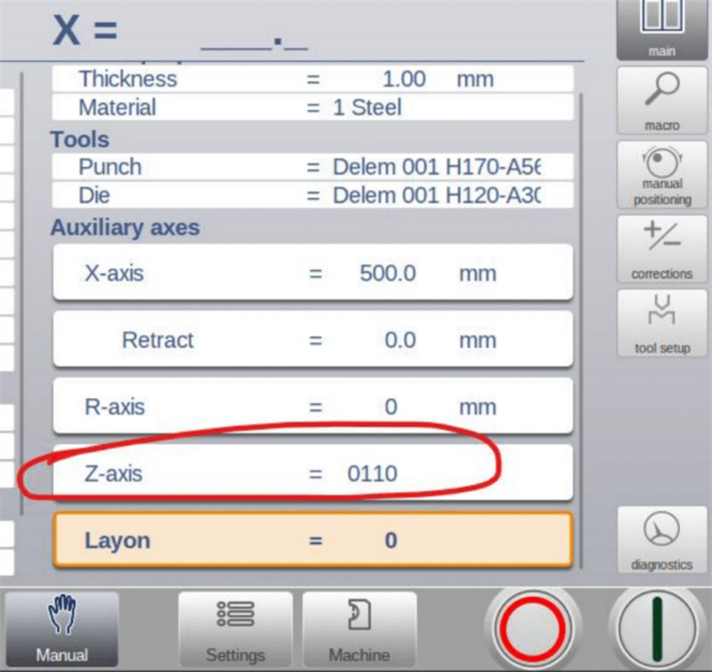
1. ფაქტობრივი ფოლადის ფურცლის სიგრძისა და ხვრელების პოზიციის მიხედვით, შეიყვანეთ სწორი Z-ღერძის პროგრამირების კოორდინატები JUGAO-ს ტაჩ-ეკრანზე;
2. DA5XT სისტემაში თითოეული პროგრამირების ნაბიჯისთვის მიანიჭეთ უნიკალური Z-ღერძის ID (ID მნიშვნელობა ორობით ფორმატშია და მისი კონფიგურაციის დიაპაზონი 0000–დან 1111-მდე შეიძლება დაყენდეს).
Როგორც ერთნაბიჯიან როგორც მრავალნაბიჯიან Z-ღერძის ექსპლუატაციის რეჟიმებში შესაძლებელია 0000–1111 ორობით დიაპაზონში Z-ღერძის ID-ების ნებისმიერი დაყენება, ხოლო სისტემა ორივე რეჟიმისთვის მომხმარებლის გასაგებად და მარტივად მოსაპოვებლად ვიზუალურ ექსპლუატაციის მაგალითებს ამოაგებს.
2. JUGAO-ს ტაჩ-ეკრანზე დეტალური ექსპლუატაცია
JUGAO-ს ტაჩ-ეკრანი Z-ღერძის ხელით და ავტომატური ექსპლუატაციის ძირეული კავშირი ადამიანსა და მანქანას შორისაა, რომელსაც სხვადასხვა სამუშაო რეჟიმისთვის განსაკუთრებულად გამორჩევადი ექსპლუატაციის ლოგიკა, ასევე არასამართლიანი სიტუაციების და ყოველდღიური კალიბრაციის საკუთარი მოსახერხებლო მეთოდები ახასიათებს.
2.1 ხელით ექსპლუატაციის მეთოდი
Z ღერძის საკუთარი მართვა ხელით შესაძლებელია მხოლოდ მაშინ, როდესაც მისი შესაბამისი ხელით მართვის ხატულა ჩნდება სპეციალურ შეხების ეკრანზე; თუ ხატულა არ ჩნდება, ხელით მართვა გამორთულია.
• წინსვლის მართვის ღილაკის დაჭერით Z1 ან Z2 გადაადგილდება პოზიციის მნიშვნელობის გაზრდის მიმართულებით (Y1 მხარე შეესაბამება Z ღერძის მინიმალური მნიშვნელობის პოზიციას, ხოლო Y2 მხარე — მაქსიმალური მნიშვნელობის პოზიციას);
• უკანსვლის მართვის ღილაკის დაჭერით Z1 ან Z2 გადაადგილდება პოზიციის მნიშვნელობის შემცირების მიმართულებით, ხოლო ღილაკის გაშვების მომენტში მოძრაობა დასრულდება მყისიერად;
• Z1 და Z2-ს შორის გადართვა: დააჭირეთ ღერძის არჩევის ღილაკს, რის შედეგად Z2 ცისფერ ფერში გამოჩნდება, რაც ნიშნავს, რომ Z2 ხელით მართვის მდგომარეობაშია; თავიდან დააჭირეთ ღილაკს, Z2 შავ ფერში დაბრუნდება და ხელით მართვის უფლება ხელახლა Z1-ზე გადავა;
2.2 ავტომატური მართვის მეთოდი
Z ღერძის ავტომატური მართვა გამოიწვევა JUGAO შეხების ეკრანზე განკუთვნილი ავტომატური სტარტის ღილაკით, რასაც წინაპირობას წარმოადგენს მოწყობილობის მდგომარეობის შემოწმება:
• თუ პრეს-ტორსის ზეთის პუმპა არ არის გაშვებული, ეკრანი მომხმარებლისთვის მოუწოდებს ჯერ ზეთის პუმპის გაშვებას;
• თუ ზეთის პუმპა ნორმალურ სამუშაო მდგომარეობაშია, ავტომატური სტარტის ღილაკის დაჭერით Z-ღერძი გადაადგილდება Id0000-ს შესაბამის წინასწარ დაყენებულ პოზიციაზე;
• ნებისმიერ დროს შეგიძლიათ ეკრანზე განკუთვნილი შეჩერების ღილაკის დაჭერით დააყენოთ Z-ღერძის ავტომატური მოძრაობა მიმდინარე მდგომარეობაში;
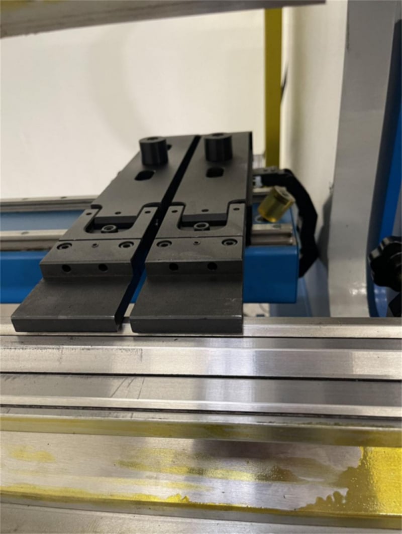
2.3 შეჯახების ავარიების შემთხვევაში არანორმალური მდგომარეობის მოსახსნელად
Z1 და Z2 შეჩერების თითებს შორის შეჯახების შემთხვევაში მოქმედებით შემდეგი რიგით:
1. ჯერ შეამოწმეთ, არის თუ არ არის Z-ღერძის მძრავი მოდულში შეტყობინების სიგნალი; თუ შეტყობინება გამოიძახება, გამორთეთ მძრავი მოდული და ხელახლა ჩართეთ მისი შეტყობინების გასაუფროებლად;
2. შეასრულეთ Z1 და Z2 ღერძების «სწავლების» კალიბრაციის ოპერაცია;
3. შეიყვანეთ შეხედულების ეკრანზე Z1 და Z2-ის მიმდინარე სრული სიზუსტის მქონე პოზიციების მნიშვნელობები და დადასტურების შემდეგ სისტემა შეძლებს ნორმალური შემდგომი მოქმედებების აღდგენას.
2.4 ძაფის ღერძის (კალიბრაციის) სწავლების მთავარი მოთხოვნები
Სწორი ძაფის ღერძის სწავლება (კალიბრაცია) არის ძაფის ღერძის კონტროლერის ნორმალური და სწორი მუშაობის ძირეული წინაპირობა, ხოლო ეს ოპერაცია უნდა შესრულდეს შემდეგ შემთხვევებში:
1. ახალი ჭედრაკის პირველი საცდელი გაშვება და ჩართვა, რომელსაც DA53T/DA58T ძაფის ღერძის კონტროლერი აღჭურვილია;
2. ძაფის ღერძის სტოპ-თითების ნებისმიერი შემთხვევითი შეჯახება ან ძაფის ღერძზე სხვა არანორმალური მექანიკური ზემოქმედება.
Მნიშვნელოვანია აღინიშნოს, რომ ძაფის ღერძის კონტროლერს აქვს გამორთვის შემდეგ მეხსიერების ფუნქცია: კალიბრირებული ძაფის ღერძის პოზიციის პარამეტრები სისტემას ავტომატურად ინახავს. მოწყობილობის გამორთვისა და ხელახლა ჩართვის შემდეგ ოპერატორს არ არის სჭიროება ხელახლა შეასრულოს სწავლების (კალიბრაციის) ოპერაცია, და სისტემა შეძლებს პირდაპირ გამოიყენოს შენახული პარამეტრები მუშაობის დროს.

