


Tärkeimmät vaiheet DELEM DA-66S -työkalukonfiguroinnissa
Sisällysluettelo
1. Johdanto
2. Perusasetukset
2.1 DELEM DA-66S -työkaluasetusliittymän avaaminen
2.2 Työkaluasetustoiminnon aktivointi
2.3 Uusien työkalujen valitseminen ja lisääminen
3. Työkalujen sijoituksen ja pituusparametrien asettaminen
3.1 Työkalun pituuden ja sijoituspaikan ohjelmointi
3.2 Automaattisen valinnan ominaisuuden tehokas käyttö
4. Laajennetut asetukset ja työkalusegmentoinnin hallinta
4.1 Työkalusegmentoinnin hallinta
4.2 Työkaluasemien valinta ja uudelleensijoittaminen
5. Usein kysytyt kysymykset (UKK)
6. Johtopäätös
DELEM DA-66S-ohjausjärjestelmän työkalujen tarkka konfigurointi ja standardivaiheiden noudattaminen ovat avainasemassa puristusmuotin käyttötehokkuuden ja koneistustarkkuuden parantamisessa. Olipa kyseessä olemassa olevan työkalukokoonpanon uudistaminen tai täysin uuden kokoonpanon luominen, jokainen konfigurointiprosessin vaihe on suoritettava huolellisesti, jotta saavutetaan optimaaliset tuotantotulokset.
Työkalukonfiguroinnin ytimenä on työntäjien, kiskojen ja kaikkien tarvittavien sovittimien tarkka ohjelmointi koneeseen. Tuotekirjaston käyttöön pääsemällä ja sopivan työkalukokoonpanoskeeman valitsemalla voidaan saavuttaa erinomainen tarkkuus näiden keskeisten komponenttien konfiguroinnissa. Tämä opas käy läpi kaikki DELEM DA-66S -työkalukonfiguroinnin olennaiset vaiheet, tehostaa työkalukokoonpanon asennustyötä ja parantaa puristusmuotin kokonaistehokkuutta.
Johdanto
DELEM DA-66S on nykyaikainen, terävän reunan saavuttamiseen tarkoitettu numeerinen ohjausjärjestelmä, jota käytetään laajalti modernissa valmistuksessa, erityisesti metalliteollisuudessa. Sen tarkka työkalukonfiguraatio on perusedellytys, jotta taivutuspaineen avulla voidaan saavuttaa korkean tarkkuuden taivutus ja vakaa suorituskyky. Virheellinen konfiguraatio vaikuttaa ei ainoastaan työkappaleiden koneistustarkkuuteen, vaan myös vähentää tuotantotehokkuutta ja voi jopa aiheuttaa tarpeetonta kulumista koneelle ja työkaluille. Siksi jokaisen käyttäjän on välttämätöntä hallita tieteelliset konfigurointivaiheet.
1 DELEM DA-66S:n työkalukonfiguraatiointerfaksin avaaminen
Jos haluat muokata tai muuttaa tietyn tuotteen työkaluasetusta, etsi ensin vastaava tuote järjestelmän tuotelibraariosta ja valitse se, minkä jälkeen siirryt työkaluasetus-moduuliin aloittaaksesi seuraavan konfigurointityön. Tämä on ensimmäinen askel ammattimaisen työkalukonfiguraatiointerfaksin avaamiseksi ja kaikkien seuraavien toimintojen perusta.
2 Työkaluasetustoiminnon aktivointi
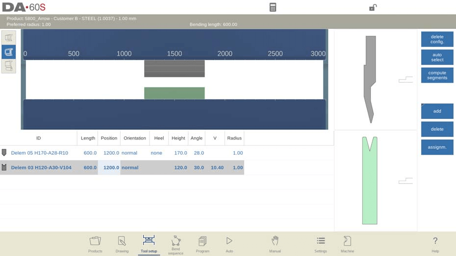
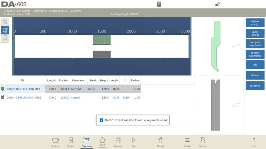
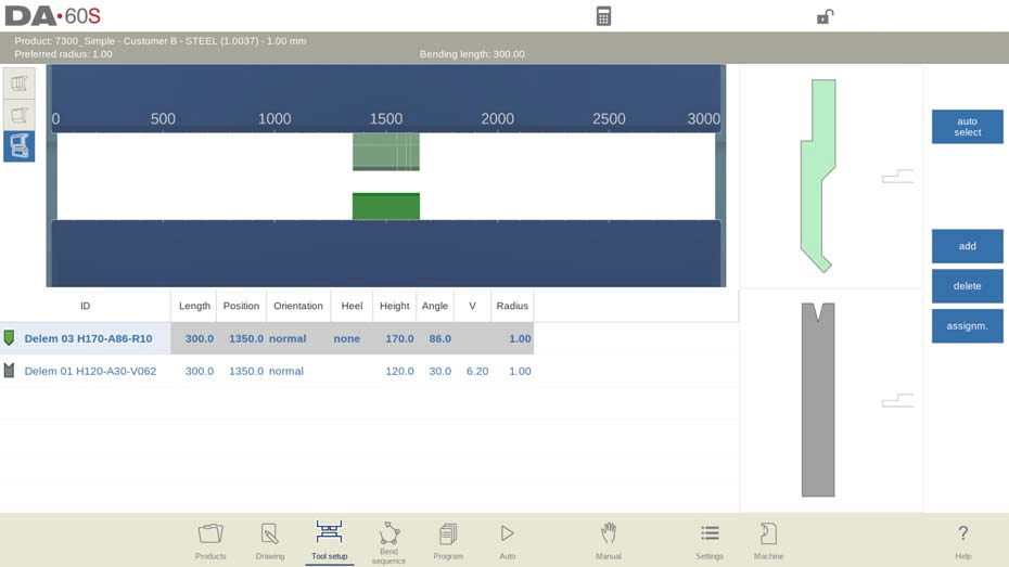
Työkaluasetuksen käyttöönotto on edellytys työkalujen määrittelylle DELEM DA-66S -ohjaimessa. Kun toiminto on otettu käyttöön, järjestelmän käyttöliittymä näyttää yksityiskohtaisen visuaalisen esityksen koneen nykyisestä työkaluasetuksesta, mikä on välttämätöntä osumatarkkojen punchien, kuoressaumien, sovittimien ja muiden työkalujen sijoittelun ohjelmoimiseksi.
Kun työkaluasetus-toiminto on otettu käyttöön, näytön yläosa esittää koneen nykyistä asetusta etunäkymänä, kun taas alaosa näyttää kaikkien määritettyjen työkalujen yksityiskohtaiset tiedot. Tällä integroidulla käyttöliittymällä operaattorit voivat ohjelmoida eri työkalujen sijoittelupaikan puristuspainimessa.
Koneen etunäkymä esittää yläosasta alaosaan perusrakenteelliset osat seuraavassa järjestyksessä: puristuspalkki, työntöadapteri (jos esiohjelmoitu), työntö, muotti, muottiadapteeri (jos esiohjelmoitu) ja työpöytä. Nämä koneenosat on valittu etukäteen järjestelmän kone-tilassa, eikä niitä yleensä tarvitse säätää päivittäisessä konfiguroinnissa. Sitä, voidaanko adapteri ohjelmoida ja lisätä asennukseen, riippuu saman kone-tilan adapteriparametrien asetuksista.
3 Uusien työkalujen valinta ja lisääminen
Uuden työkalukonfiguraatiokaavion luomisen yhteydessä koneen työkaluasennusalue on oletusarvoisesti tyhjä. Operaattorin on lisättävä vaaditut työkalut manuaalisesti; nämä voivat olla työnnöksiä, muotteja tai adaptereita (jos järjestelmässä on otettu käyttöön adapteritoiminto). Kun työkalu on lisätty, se sijoitetaan koneeseen oletusarvoisesti suurimmalla mahdollisella pituudella, ja operaattori voi sen jälkeen muokata työkalutunnusta (Tool ID) luettelonäkymästä tarkempaa työkalujen vastaavuutta ja hallintaa varten.
Tietty toimintaprosessi on seuraava:
1. Kun olet siirtynyt uuden työkalukonfigurointitilaan, vahvista, että koneen työkalun avauminen on tyhjässä tilassa;
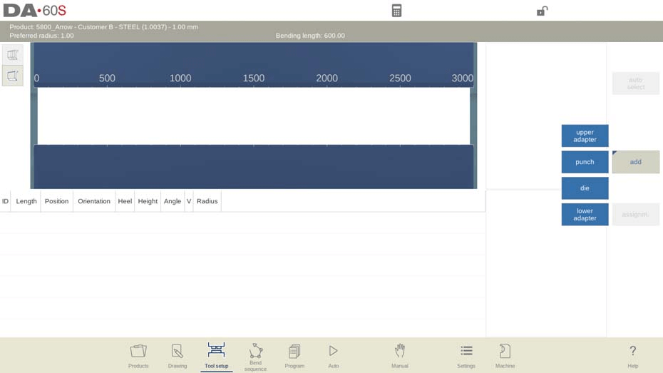
2. Napsauta "Lisää"-painiketta valitaksesi lisättävä työkalutyypin (pistotyökalu, muottityökalu tai käytössä oleva sovittimet);
3. Kun olet valinnut työkalun (esimerkiksi pistotyökalun), järjestelmä sijoittaa sen automaattisesti koneen määritettyyn paikkaan suurimmalla mahdollisella pituudella;
4. Valitse rajapinnasta Pistotyökalun tunniste (Punch ID) ja napsauta luettelonäkymää muokataksesi työkalun yksilöllistä tunnistetta myöhempää tunnistamista ja hallintaa varten.
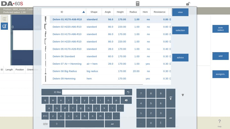
Järjestelmä on varustettu älykkäällä työkalun tunnisteen suodatusfunktiolla: kun syötetään vain osa työkalun tunnistetta, ohjausjärjestelmä vastaa automaattisesti ja näyttää luettelon työkaluista, joiden nimissä esiintyy syötetyt merkit, mikä nopeuttaa huomattavasti työkalujen valintaprosessia.
Näppäimen "Neuvonta" painaminen käyttöliittymässä käynnistää järjestelmän, joka suodattaa ja näyttää rajatun määrän sopivia työkaluja koko työkalukirjastosta tiettyjen kriteerien perusteella, mikä auttaa käyttäjiä löytämään nopeasti parhaat vaihtoehdot. Suodatuskriteerit ovat seuraavat:
• Tuotteen säteen vastaavuus: valitun työkalun on tuotettava käsiteltävästä tuotteesta säde, joka on mahdollisimman lähellä esiasetettua suositeltavaa sädettä, ja todellisen tuloksena syntyvän säteen on oltava suositellun säteen ±50 %:n sisällä;
• Taivutusvoiman noudattaminen: käsittelyyn vaadittavan taivutusvoiman ei saa ylittää valitun työkalun kuormituskestävyyttä;
• Työkalun kulman sopeutuminen: valitun työkalun kulman on oltava pienempi tai yhtä suuri kuin käsiteltävän tuotteen vaatima kulma;
• Taivutusmenetelmän vastaavuus: esimerkiksi reunakääntötyökaluja suositellaan automaattisesti, kun tuotteen käsittely vaatii reunakääntötaivutusprosesseja.
Näppäimen "Näytä kaikki" painaminen peruuttaa suodatuksen ja näyttää koko työkalukirjaston työkalujen täydellisen luettelon, josta käyttäjät voivat valita.
3.1 Moni-V-työkalun esivalinta
Moni-V-työkalulle (työkalulle, jossa on useampi kuin yksi V- tai U-muotoinen aukko) käyttäjä voi valita joko tietyn V/U-aukon tai koko moni-V-työkalun (merkitty V = *). Jos valitaan tietty aukko, järjestelmä käyttää tätä aukkoa koko taivutusjärjestyksen laskennassa; jos valitaan koko moni-V-työkalu, ohjausjärjestelmä valitsee automaattisesti sen aukon, joka mahdollistaa tuotteen säteen saamisen mahdollisimman lähelle ennalta ohjelmoitua arvoa.
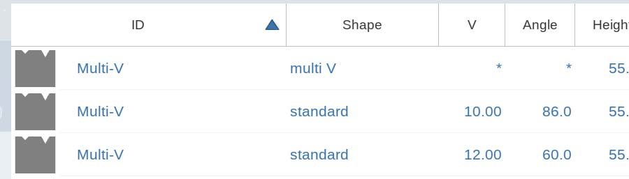
Jos järjestelmä valitsee toisen V/U-aukon taivutusjärjestyksen laskennan aikana, tämä uudelleen valittu aukko otetaan käyttöön kaikissa seuraavissa taivutusprosesseissa, jotka eivät ole vielä sisällytetty alkuperäiseen järjestykseen.
3.2 Vario-V-työkalun valinta ja parametrien asettaminen
Vario-V-muottien (eli säädettävän V-/U-muotoisen aukeaman muottien) alustava valintaprosessi DELEM DA-66S -ohjelmistossa on sama kuin tavallisten muottien tapauksessa. Kun Vario-V-muotti on valittu, sen V-arvoa ei aseteta oletusarvona. Käyttäjä voi siirtyä suoraan taivutusjärjestyksen luomiseen, ja järjestelmä valitsee automaattisesti sopivimman V-arvon Vario-V-muotin saatavilla olevien säätöasentojen perusteella.
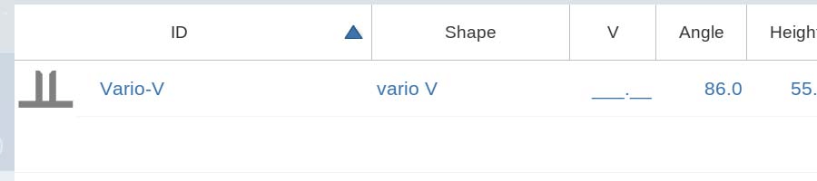
Jos käyttäjä esiasettaa tietyn V-arvon, järjestelmä käyttää tätä arvoa kaikissa seuraavissa taivutuslaskuissa. Diskreeteillä säätöasennoilla varustetuille Vario-V-muoteille voidaan valita ainoastaan esiasetettuja kiinteitä arvoja; jos annetaan ei-esiasetettu V-arvo, järjestelmä valitsee automaattisesti lähimmän saatavilla olevan kiinteän arvon.
Taivutusjärjestelmätilassa käyttäjät voivat muokata monitasoisien V-muottien V-avautumaa tai Vario-V-muottien V-arvoa käyttämällä käyttöliittymässä olevia Muokkaa- tai Siirrä-muottifunktioita. Ohjelmatilassa oleva Muottien sijoitus -toiminto tarjoaa myös saman parametrin säätömahdollisuuden.
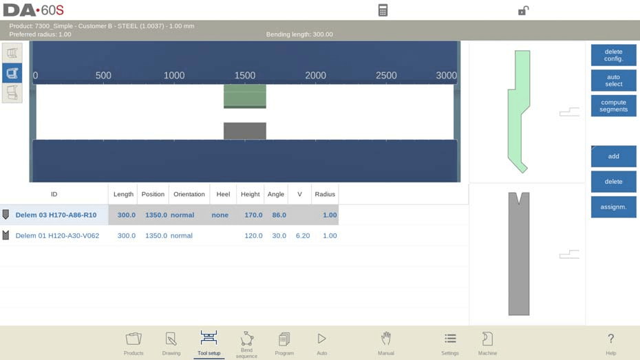
Työkalujen sijoituksen ja pituuden parametrien asettaminen
1 Ohjelmoi työkalun pituus ja sijoituspiste
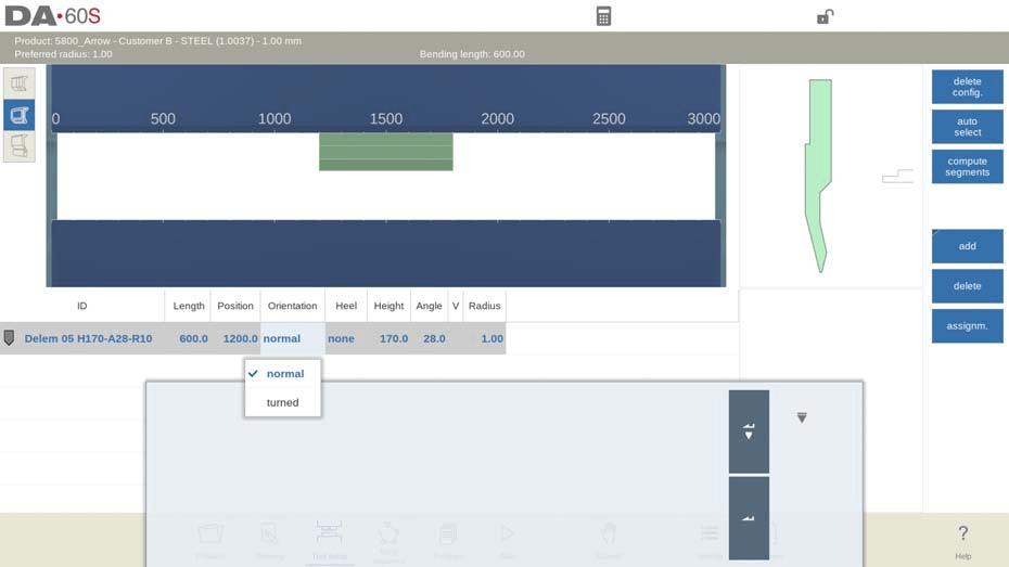
Työkalujen pituuden ja sijoituspisteen säätäminen DELEM DA-66S -järjestelmässä on yksinkertaista ja intuitiivista. Käyttäjät voivat joko valita kohdetty työkalun ja syöttää suoraan uudet numeeriset arvot pituudelle ja sijoitukselle tai vetää työkalua visuaalisessa käyttöliittymässä uudelleen sijoittaakseen sen. Järjestelmän vetotoiminto on optimoitu nopeuden säätöominaisuudella: mitä pidempi alaspäin vetäminen, sitä hitaammin työkalu liikkuu, mikä mahdollistaa erinomaisen tarkan työkalujen sijoituksen ja parantaa huomattavasti konfiguroinnin tarkkuutta.
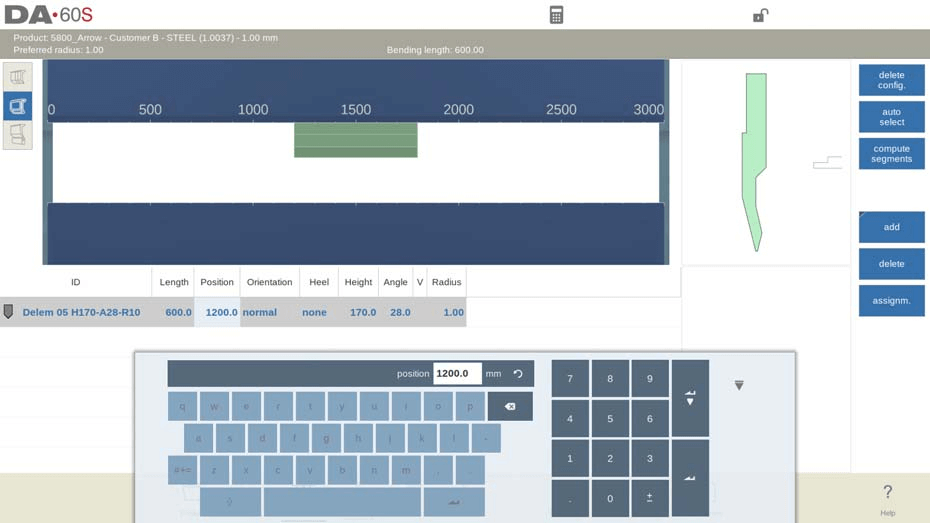
Napsautustoiminto on merkittävä ja välttämätön ominaisuus tarkkaan työkalujen sijoittamiseen DELEM DA-66S -työkalukonfiguraatiossa. Kun työkaluja tai työkaluasemia siirretään käyttöliittymässä, napsautustoiminto tasaa automaattisesti kohteen koneen keskikohdan kanssa joko pysty- tai vaakasuunnassa. Kun työkalu siirretään napsautusalueelle, näytölle ilmestyy punainen ohjausviiva, joka osoittaa optimaalisen vapautusasennon tarkan sijoituksen varmistamiseksi – tämä ominaisuus on avain työkalujen sijoituksen tarkkuuden ja myöhempänä suoritettavan koneistuksen vakauden varmistamiseen.
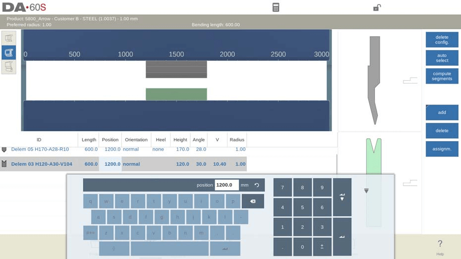
Lisäksi DELEM DA-66S -järjestelmässä on älykäs sovitusfunktio: kun työkalupää on asetettu paikalleen, järjestelmä asettaa automaattisesti sen suoraan alle vastaavan kylvyn, ja kylvyn pituus sekä sijoituspiste sovittuvat täysin työkalupään kanssa. Tämän perusteella käyttäjät voivat tehdä tuotannon tarpeiden mukaisia henkilökohtaisia mukautuksia, kuten lisätä tai poistaa työkalupäitä ja kylvyjä, siirtää työkalujen sijainteja, säätää työkalujen pituuksia, muuttaa työkalujen kallistuskulmia tai muokata kantatyyppejä. Nämä joustavat säätömahdollisuudet mahdollistavat työkalukonfiguraation sopeuttamisen monenlaisiin monimutkaisiin tuotanto- ja käsittelyvaatimuksiin.
Tämän vaiheen avainpainikkeet:
• Poista konfiguraatio: Tyhjentää olemassa olevan kokonaisen työkalukonfiguraatiojärjestelmän ja aloittaa uuden konfiguraation alusta;
• Lisää: Lisää uusi työkalu nykyiseen konfiguraatioon ja napsauta valitaksesi työkalun tyyppi (yläadapteri (jos käytössä), työkalupää, kylvy, alaadapteri (jos käytössä));
• Poista: Poista tällä hetkellä valittu yksittäinen työkalu konfiguraatiosta.
2 Hyödynnä automaattista valintaa parhaalla mahdollisella tavalla
"Automaattinen valinta" -toiminto on saatavilla työkalukonfiguraation ydinkäyttöliittymässä, ja sen tarkoituksena on auttaa käyttäjiä valitsemaan nopeasti sopivin nuppauksen ja kiskon yhdistelmä esiohjelmoituun taivutusprosessiin tuotteen suurimman taivutusviivan perusteella.
Järjestelmä hakee ja yhdistää automaattisesti työkalukirjastosta optimaalisen työkalupaketin yhteen taivutusprosessiin, jotta saavutettaisiin mahdollisimman ideaali tuotteen kaarevuussäde. On huomattava, että tämä toiminto yhdistää työkalut vain yhteen taivutusvaiheeseen eikä se luo koko tuotantoprosessin kokonaistyökaluasetusta—koska taivutusjärjestys on keskeinen rajoite koko asetusten muodostamisessa ja sen on määriteltävä käsin operaattorien toimesta. Kun automaattisen valinnan toiminto on otettu käyttöön, järjestelmä korvaa automaattisesti olemassa olevan työkaluasetuksen uudella, parhaalla yhdistelmällä.
Edistynyt konfigurointi ja työkalujen segmentointihallinta
1 Työkalujen segmentoinnin hallinta
Segmentoituja työkaluja varten DELEM DA-66S -järjestelmä voi automaattisesti laskea optimaalisen segmentointikuvion etukäteen määritettyjen segmentin pituusparametrien perusteella, mikä varmistaa, että segmentoidut työkalut soveltuvat täydellisesti taivutuspuristimen rakenteellisiin rajoituksiin ja parantavat tehokkaasti taivutusprosessin tehoa.
Järjestelmän tuki segmentoituun työkalukonfiguraatioon tuo tuotantoon suurta joustavuutta ja tarkkuutta: käyttäjät voivat yhdistää vaaditun kokoisia työkaluja järkevällä segmentoinnilla, mikä on erityisen käytännöllistä erilaisten työkappaleiden erilaisia työkaluvaatimuksia silmällä pitäen ja tekee työkalukonfiguraatiosta tarkemmin kohdennetun ja tehokkaamman.
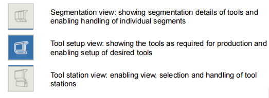
DELEM DA-66S:n työkaluasetusliittymässä on kolme erillistä näkymätilaa, joista jokainen tarjoaa yksilöllisen toiminnallisen näkökulman työkaluasetuksen ja segmentointihallinnan tukemiseksi. Näkymiä voidaan vaihtaa napsauttamalla valintapainikkeita koneen etunäkymän vasemmalla puolella, mikä tekee segmentoiduilla työkaluilla suoritettavasta toiminnosta yksinkertaisen ja intuitiivisen.
1.1 Tärkeimmät toiminnot yksittäisen työkalun segmentointiin
• Taivutusjärjestyksen laskenta: Kun perustyökaluasetukset on suoritettu, siirry taivutusjärjestystilaan, jolloin järjestelmä laskee automaattisesti tehokkaimman taivutusjärjestyksen määritetyille työkaluille, mikä merkittävästi nopeuttaa koko tuotantoprosessia;
• Manuaalinen työkalun segmentointi: Jos oletustyökalun pituus ei täytä käsittelyvaatimuksia, operaattorit voivat jakaa työkalut manuaalisesti säätääkseen niiden pituuden tarkalleen vaadittavaksi, mikä lisää konfiguroinnin joustavuutta;
• Automaattinen segmentointilaskenta: Järjestelmän sisäänrakennettu segmentointitoiminto voi automaattisesti määrittää optimaalisen segmentointiratkaisun todellisten tuotantoparametrien perusteella. Laskennan perustana ovat tärkeät parametrit, kuten "suurin väli työkalujen välillä" ja vaihtoehtoinen "työkalun pituuden toleranssi", mikä tekee segmentoinnista tieteellisempää ja käytöstä käyttäjäystävällisempää.
Operaattoreille, jotka tarvitsevat syvällistä työkalusegmentoinnin mukauttamista, DELEM DA-66S-tuote tukee suoraa segmenttiparametrien ohjelmointia koneentilassa. Tässä tilassa operaattorit voivat muokata työkalukirjaston nuppityökalujen ja kuulatyökalujen segmenttiparametrejä, jolloin työkaluasettelu täyttää täysin erityisten tuotantoprosessien tarkat vaatimukset. Työkalukirjaston segmentti-ohjelmointimenetelmän hallinta on avain DELEM DA-66S:n työkalukonfiguraatiofunktion täyteen hyödyntämiseen.
1.2 Työkalunäkymä: Määriteltävän parametrin asettaminen
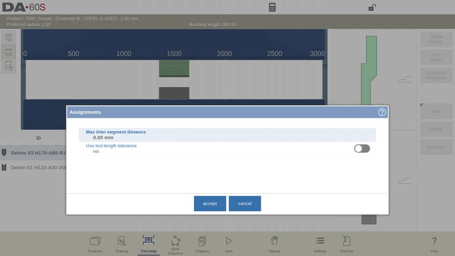
Napsauta käyttöliittymässä olevaa "Tehtävät"-painiketta nähdäksesi ja määrittääksesi segmentointilaskennassa käytettävät perusparametrit. Määriteltävissä olevat tehtäväparametrit ovat:
• Suurin väli segmenttien välillä: Aseta suurin sallittu etäisyys vierekkäisten työkalusegmenttien välillä;
• Käytä työkalun pituustoleranssia: Ota käyttöön tai poista käytöstä toleranssiparametri, jolla säädellään sallittua poikkeama-aluetta työkalusegmentoinnissa.
1.3 Segmentointinäkymä: segmenttien säätö ja hallinta
Siirryttyäsi segmentointinäkymään käyttöliittymä näyttää työkalujen segmenttitiedot sekä graafisessa että luettelomuodossa, ja näytetään ainoastaan tällä hetkellä valitun työkalun segmenttitiedot. Käyttäjä voi raahata ja muokata yksittäisten segmenttien sijaintia ja kokoa graafisella käyttöliittymällä, ja luettelossa näytetään selkeästi kaikkien nykyisen työkalun segmenttien koostumus ja parametritiedot.
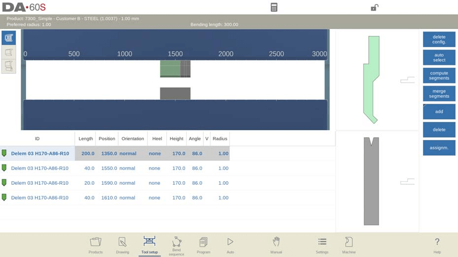
On huomattava, että segmenttien säätämisessä segmentointinäkymässä järjestelmä ei ota huomioon segmenttien todellista varastotilannetta; säädetyn kaavion ja todellisen varaston välistä yhteensovittuvuutta voidaan tarkistaa suorittamalla segmentointilaskenta uudelleen. Lisäksi työkalun pituuden tai työkalun tyypin muuttaminen aiheuttaa olemassa olevan segmentointikaavion poistamisen, ja käyttäjän on luotava segmentointiparametrit uudelleen.
1.4 Segmenttiparametrien asettaminen työkalukirjastossa
Jotta järjestelmä voi käyttää segmentoituja työkaluja ja laskea segmentointikaavan perustuen todellisiin saatavilla oleviin segmentteihin, käyttäjien on ensin täydennettävä segmenttikirjaston tiedot. Tämä toiminto voidaan suorittaa työkaluohjelmointimoduulissa, joka sijaitsee kone-tilassa nuppityökalun ja kuumakäsiteltyjen työkalujen ominaisuuksien asetuksissa.
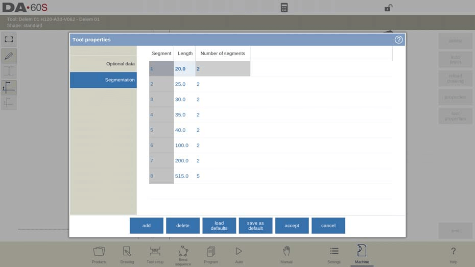
Työkalun ominaisuuksien asetuksissa siirrytään segmentointivälilehdelle, jossa käyttäjät voivat ohjelmoida ja asettaa segmentin pituuden, valinnaisen kantamuodon sekä työkalulle saatavilla olevan segmenttien määrän, mikä muodostaa järjestelmän automaattisen segmentoinnin laskennan perustan.
2 Työkaluasemien valinta ja uudelleensijoittaminen
Asemakatsauksen käytön hallinta on keskeinen osa edistyneitä työkalukonfigurointeja DELEM DA-66S -ohjelmistossa, jota käytetään pääasiassa työkaluasemien yleishallintaan, ja sen perustoiminnot sekä käyttökohteet ovat seuraavat:
1. Korostaminen ja uudelleensijoittaminen: Asemakatsauksessa koko työkaluasema näkyy korostettavana yksikkönä, mikä mahdollistaa nopean valinnan käyttäjälle. Työkaluaseman uudelleensijoittaminen voidaan toteuttaa kahdella tavalla: suoraan ohjelmoimalla uusi koordinaattipaikka tai raahaamalla asema visuaalisella käyttöliittymällä haluttuun paikkaan, mikä parantaa huomattavasti kokonaistyökalukokoonpanon joustavuutta;
2. Työkaluasemien automaattinen määrittäminen: Järjestelmä tunnistaa ja määrittelee työkaluaseman automaattisesti, kun nuppula ja muottipinta ovat päällekkäin. Tämä päällekkäisyys voi olla tarkka kohdistusasento tai hieman siirretty asento, ja molemmat tunnistetaan kelvollisiksi työkaluasemiksi. Myös erityinen konfiguraatio, jossa kaksi nuppulaa vastaa yhtä muottipintaa, voidaan määritellä työkaluasemaksi, mikä on erityisen hyödyllistä taivutusprosessien käsittelyyn tilallisten rajoitusten vallitessa;
3. Työkaluasemien hallinta: Asemanäkymässä käyttäjä voi kopioida olemassa olevan työkaluaseman "lisää"-painikkeella tai poistaa tarpeettoman aseman "poista"-painikkeella. Tämän näkymän tärkein ominaisuus on se, että se hallinnoi työkaluasemaa kokonaisuutena eikä muuta yksittäisten työkalujen yksityiskohtaisia parametrejä asemassa, mikä tekee kokonaissäädön tehokkaammaksi ilman, että yksittäisen työkalun tarkka konfiguraatio vaarantuisi.
Usein kysyttyjä kysymyksiä
K1: Kuinka saavuttaa tehokas työkaluasetus DELEM DA-66S -työkalukonfiguraatiossa?
A1: Työkaluasetuksen tehokkuuden maksimoimiseksi siirry ensin taivutusjärjestys-tilaan, jotta järjestelmä laskee tuotannon todellisen tehtävän kannalta tehokkaimman taivutusjärjestyksen. Käytä sen jälkeen järjestelmän työkalujen jakamistoimintoa työkaluosien säätämiseen ja halutun työkalun pituuden luomiseen käsittelyä varten. Näiden kahden toiminnon yhdistäminen voi merkittävästi lyhentää asennusaikaa ja parantaa konfigurointitehokkuutta.
K2: Kuinka määritellä työkaluasemat DELEM DA-66S -työkalukonfiguraatiossa?
A2: DELEM DA-66S -järjestelmässä työkaluasema määritellään automaattisesti, kun nuppula ja kohdeovikko ovat päällekkäin. Tämä määrittely sisältää sekä tarkat päällekkäiset sijainnit että siirretyt päällekkäiset sijainnit, mikä mahdollistaa tehokkaan sopeutumisen monimutkaisten taivutusprosessien ja erilaisten työkalukonfiguraatioiden käsittelyvaatimuksiin.
K3: Voiko yksittäisen työkalun yksityiskohtaisia parametrejä muuttaa aseman näkymässä konfiguroinnin aikana?
V3: Ei. Aseman näkymää käytetään vain työkaluasemien kokonaishallintaan ja se tukee toimintoja, kuten asemien kopioimista, poistamista ja uudelleensijoittamista, mutta sillä ei voida muuttaa yksittäisten työkalujen yksityiskohtaisia parametrejä. Tämä suunnittelu varmistaa, että työkaluaseman kokonaismuokkaus ei vaikuta yksittäisen työkalun tarkkaan konfiguraatioon.
Johtopäätös
Tarkka CNC-työkalukonfiguraatio DELEM DA-66S -ohjausjärjestelmässä on keskeinen takuu leikkuupuristimen korkean tarkkuuden ja tehokkuuden saavuttamiseksi. Yllä mainittujen keskeisten konfigurointivaiheiden noudattaminen tarkasti varmistaa, että työkaluasetukset sopeutuvat täysin tuotteen erityisiin käsittelyvaatimuksiin, mikä parantaa koneen työstötarkkuutta ja tuotantotehokkuutta tehokkaasti. Jokapäiväisessä tuotannossa käyttäjien on säännöllisesti tarkistettava ja säädettävä työkalukonfiguraation parametreja todellisen käsittelytilanteen ja työkappaleen vaatimusten mukaan, jotta leikkuupuristimen optimaalinen toimintatila säilyy.
Syvällisempiä ammattimaisia näkemyksiä ja teknistä tukea DELEM DA-66S -työkalukonfiguraatiosta varten voitte ottaa yhteyttä JUGAO:n ammattimaiseen tekniseen tiimiin. Olemme sitoutuneet tarjoamaan kattavaa tukea koneenne asennukseen ja jokapäiväiseen käyttöön, mikä varmistaa koko tuotantoprosessinne sujuvan etenemisen.

