


Kuinka korjata viallinen anturi putken taivutuskoneessa?
Anturit ovat putkien taivutuskoneen "hermoärsykkeen päät", ja niiden tehtävänä on seurata tärkeitä parametrejä, kuten taivutuskulmaa, työntimen sijaintia, kiinnitystilan tilaa ja syöttöliikettä. Jos anturi epäonnistuu, laitteisto saattaa kokea kulmavirheitä, poikkeavaa toimintaa tai hälytyspysäytystä. Anturivirheiden diagnosoimisen ja korjaamisen hallinta on tärkeä taito laitteiston normaalin toiminnan varmistamiseksi.
Yleisimmät anturityypit ja niiden vioittumisen oireet
Putkien taivutuskoneissa yleisesti käytetyt anturit ovat:
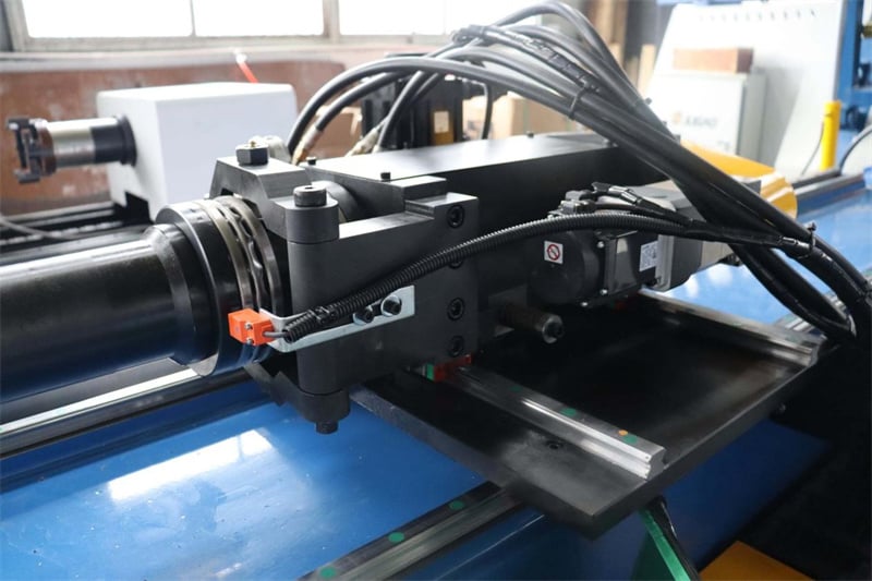
Kulma-anturi/kooderi: Seuraa taivutusvarren kiertokulmaa. Vioittumisen oireet: Suuret taivutuskulmavirheet, epänormaali kimpoaminen, kulman näyttö vaihtelee voimakkaasti tai signaalia ei saada lainkaan.
Läheisyyskytkin: Tunnistaa aseman signaalit, kuten työntimen eteen- ja taaksepäin liikkumisen, puristusaseman sekä syöttölähtöaseman. Vian oireet: Ei reaktiota, virheellinen aktivoituminen ja epävakaa signaali.
Siirtymäanturi: Mittaa sylinterin iskunpituutta tai syöttöpituutta. Vian oireet: Epätarkat mitat, signaalin vaihtelut ja näytössä näkyvien arvojen vaihtelu.
Vianmääritys ja korjaustoimet
Vaihe 1: Virran katkaisu ja turvallisuuden varmistus
Ennen kuin suoritat mitään anturien huoltoa, katkaise aina laitteen päävirtalähde ja vapauta hydraulijärjestelmän paine estääksesi tahattoman toiminnan ja mahdolliset vammat.
Vaihe 2: Visuaalinen tarkastus
Tarkasta anturi halkeamien, muodonmuutosten tai öljysaastumisen varalta. Tarkista löysentyneet tai hapettuneet liittimet sekä kuluneet tai rikki menneet kaapeliverhot. Tarkista tunnistuspinta pölyn tai metallijätteiden varalta – tämä on yleinen läheisyyskytkinten vian syy.
Vaihe 3: Sähköisten parametrien testaus
Käytä multimetria suorittaaksesi kolme tärkeää testiä: tarkista, onko virtalähteen jännite sisällä nimellisalueella (esim. DC12–24 V tai AC90–250 V); tarkista, onko lähtösignaalin jännite normaali; tarkista, ylittääkö kuorman virta nimellisarvon. Koodareille käytä oskilloskooppia tarkistamaan, onko lähtösignaalin aaltomuoto vakaa ja täyttääkö amplitudi vaaditut vaatimukset.
Vaihe 4: Signaalin ja häiriöiden vianmääritys
Varmista, että anturin asennuspaikka on turvallinen ja että mittauskohteen havaitsemisetä on sopiva etäisyys. Tarkista, ettei läheisyydessä ole voimakkaita elektromagneettisia häiriölähteitä (esim. taajuusmuuttajia tai korkeatehoisia moottoreita). Tarvittaessa lisää signaalijohdolle suojakuoret ja maadoita se yhdestä päästä.
Vaihe 5: Kalibrointi ja parametrien tarkistus
Jos kulmapoikkeama on suuri, anturin nollapiste on kalibroitava uudelleen. Tarkista, ovatko anturin parametriasetukset ohjausjärjestelmässä oikein, kuten mittausalue ja viestintäprotokolla. Koodareille tarkista myös, onko yhdistävä avain irronnut avainurasta ja ovatko valo-optiset komponentit likaisia.
Vaihe 6: Vaihda viallinen anturi
Jos edellä mainitut vaiheet eivät ratkaise ongelmaa, tämä viittaa siihen, että anturin sisäiset komponentit ovat vaurioituneet, ja anturi on vaihdettava saman mallisen anturin kanssa. Vaihtoa suorittaessa varmista, että virta on katkaistu, liitä johtimet oikein, kalibroi parametrit uudelleen vaihdon jälkeen ja suorita testiajo tarkistusta varten.
Ennaltaehkäisevän huollon suositukset
Puhdista anturin tunnistuspinta säännöllisesti estääksesi öljyn ja pölyn vaikutuksen havaintoherkkyyteen.
Kalibroi anturi joka kuudes kuukausi varmistaaksesi mittauksen tarkkuuden.
Pidä varasensorien varastoa; suositellaan, että kriittisissä paikoissa oleviin sensoreihin varataan varaosia.
Valitse sensoreita, joiden suojaluokka on korkeampi (esim. IP67 tai korkeampi), kovien ympäristöjen käyttöön.
Ota huomioon sensorin käyttölämpötila-alue, jotta sen nimellisarvoa ei ylitetä, mikä voi johtaa suorituskyvyn heikkenemiseen.
Vaikka sensorit ovat pieniä, ne vaikuttavat suoraan putkien taivutustarkkuuteen ja laitteiston turvallisuuteen. Standardoitujen diagnostiikka- ja korjausmenettelyjen hallinta mahdollistaa ongelmien nopean paikantamisen ja käytöstäpoikkeamien vähentämisen.

