


Trin-for-trin-processen til oprettelse af produkttegninger med DELEM DA-58T
At oprette præcise og højeffektive produkttegninger er en afgørende del af metalbearbejdningens produktion, og DELEM DA-58T-systemet tilbyder en professionel løsning til denne kritiske opgave. At mestre det standardiserede tegningsforløb for dette system sikrer ikke kun præcisionen af metalbearbejdningsdele, men optimerer også hele produktionsarbejdsgangen. Uanset om du er nybegynder, der lærer DELEM DA-58T at kende, eller en erfaren operatør, der ønsker at forbedre dine tegnefærdigheder, vil denne detaljerede vejledning føre dig gennem de centrale trin og de vigtigste betjeningspunkter ved oprettelse af produkttegninger med systemet og hjælpe dig med at udnytte dets fulde funktionspotentiale.
Indstilling af generelle produktegenskaber
Det første trin i oprettelsen af en produkttegning med DELEM DA-58T er at konfigurere de generelle produktegenskaber, hvilket danner grundlaget for hele tegningsprocessen.
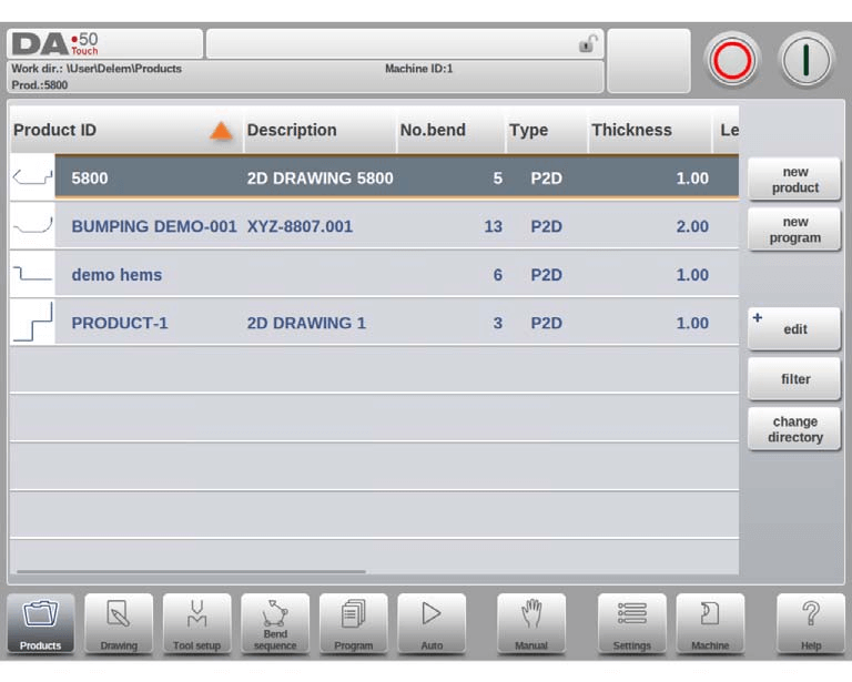
Hvis du skal redigere en eksisterende tegning, vælger du blot det tilsvarende produkt fra systemets produktbibliotek og klikker på tegningsindstillingen for at åbne den. For en helt ny produkttegning starter du processen ved at vælge Nytt Produkt i produktbiblioteket, hvilket åbner brugergrænsefladen til opsætning af de generelle produktegenskaber – alle parametre her skal indstilles, før du kan fortsætte til den formelle tegningsfase.
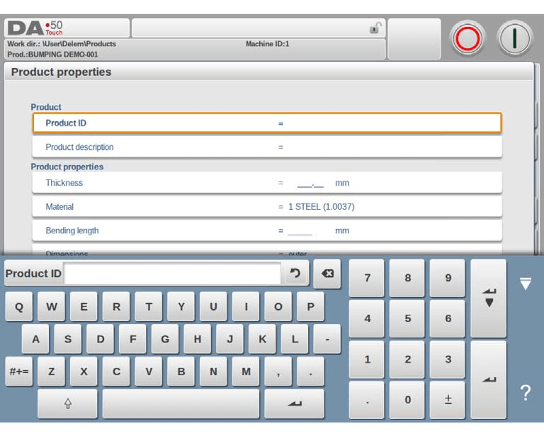
To kerneidentifikationsparametre kræver omhyggelig indtastning: Produkt-ID'et, en unik identifikator for hvert produktprogram med en grænse på 25 tegn (understøtter en blanding af bogstaver og tal), og Produktbeskrivelsen, som også er begrænset til 25 tegn og bruges til at kort beskrive programmets anvendelse og formål. Hvis du indtaster et Produkt-ID, der allerede findes i systemet, vises en advarsel, der spørger, om du vil overskrive den oprindelige produktdata. Ved at vælge "ja" slettes den tidligere produktinformation, mens "nej" kræver, at du indtaster et nyt, unikt ID.
Desuden skal du indstille en række nøgletekniske parametre:
• Tykkelse: Indtast den specifikke tykkelse af den plade, der skal bearbejdes.
• Materiale: Vælg mellem fire forudindstillede materialetyper i systemet; yderligere materialer kan programmeres i indstillingsmodulet og aktiveres ved valg, når det er nødvendigt.
• Bøgelængde: Definer pladens længde langs Z-aksen.
• Mål: Vælg enten ydre (A) eller indre (B) mål for nye flader og sider, hvor standardindstillingen bestemmes af parameteren Standardmål i systemets indstillingsfunktion.
• Radius: Efter værktøjsvalg i værktøjsopsætningsfasen vil systemet automatisk genberegne produktets radius; hvis du ønsker at beholde den oprindelige indstilling, skal du vælge muligheden "brug programmeret", så genberegning deaktiveres.
• Bøjefrihed: Vælg mellem "brug beregnet" (ved anvendelse af Delem-formlen) og "brug programmeret" (ved anvendelse af systemets bøjefrihedstabel), afhængigt af de faktiske bearbejdelseskrav.
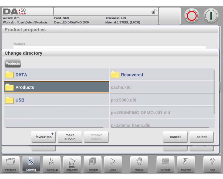
For at ændre den aktive gemmekatalog for tegningen skal du bruge funktionerne "Gem som" og "Skift katalog" – den aktuelle tegningsfil kopieres automatisk til den nyvalgte katalog for en praktisk filhåndtering.
Oprettelse af en 2D-produkttegning
Når alle generelle produktdata er indstillet korrekt, indlæser systemet 2D-tegningsgrænsefladen, hvor du kan begynde at udarbejde produktprofilen.
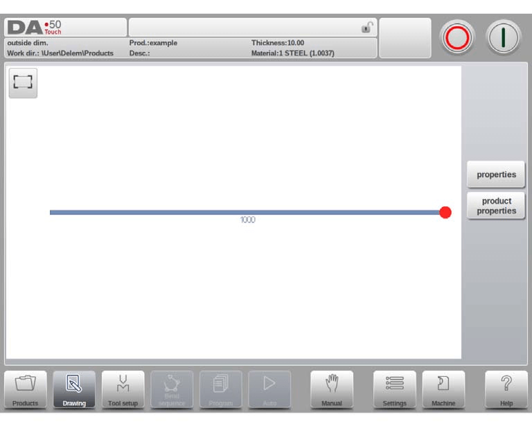
Den øverste informationslinje i tegningsgrænsefladen viser nøgleproduktinformationer, herunder produkt-ID, beskrivelse og grundlæggende dimensioner til hurtig reference. Du kan først bruge systemets "skitse"-tilstand til at oprette en foreløbig produktprofil: Tryk blot på grænsefladen for at skitsere den grundlæggende form, og indtast derefter præcise dimensioner og andre tekniske værdier via tastaturet for at forfine designet. Direkte tastaturindtastning af bøjenheder og sidelængder (bekræftet ved at trykke på Enter-tasten) understøttes også, hvilket giver mulighed for fleksibel og effektiv tegning.
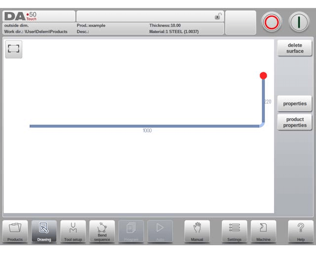
Denne iterative designproces fortsætter, indtil den ønskede produktprofil er opnået. Hvis justeringer er nødvendige under tegningen, kan du ændre de centrale produktdata i afsnittet Produktens egenskaber; for finjustering af enkelte vinkler og linjer vælger du det målrettede element og klikker på muligheden Egenskaber for at foretage ændringer. Systemet fremhæver det aktuelle aktive element (enten en linje eller en vinkel) for klar operativ feedback og understøtter grafisk programmering af op til 99 bøjninger pr. produkt, hvilket imødekommer behovene ved kompleks delbehandling.
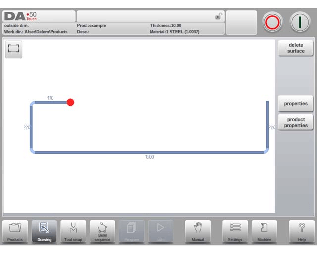
Når 2D-produkttegningen er færdig, kan du fortsætte til de efterfølgende programmeringsfaser i DELEM DA-58T-systemet: først afslut konfigurationen af værktøjsopsætning, derefter fastlæg bøjefølgen for pladebehandlingen.
Konfigurering af linjeegenskaber
Linjeegenskaber er en afgørende detalje i 2D-tegning, og DELEM DA-58T giver mulighed for at tilpasse hver enkelt produktlinjes parametre ved at vælge indstillingen «Egenskaber», når markøren befinder sig på den pågældende linje. De centrale konfigurerbare linjeegenskaber omfatter projekteringsindstillinger og præcisionsvalg, begge af hvilke har direkte indflydelse på tegningens nøjagtighed og muligheden for efterfølgende bearbejdning.
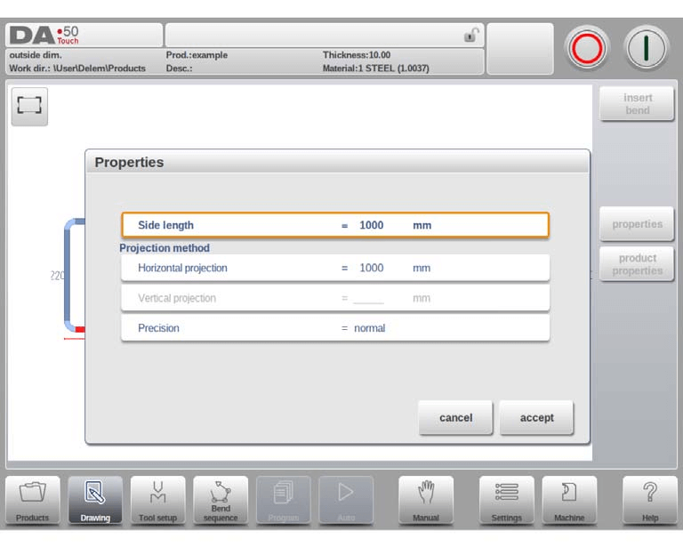
Projekteringsindstillinger
I vinduet til linjeegenskabsindstilling kan du programmere to centrale projekteringsparametre for den valgte linje:
• Vandret projektion: Den faste vandrette afstand for linjen, uafhængigt af dens faktiske vinkel.
• Lodret projektion: Den faste lodrette afstand for linjen, uanset dens faktiske vinkel.
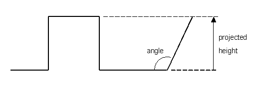
Projektionsfunktionen er et praktisk værktøj til tegning af diagonale linjer: den eliminerer behovet for manuel beregning af præcise sidelængder. Indtast blot den ønskede vandrette eller lodrette projektionsafstand for den valgte linje, og tryk på Enter; systemet beregner og anvender derefter automatisk den nøjagtige linjelængde på segmentet. Systemet angiver den normale linjelængde som L, den lodrette projektionslængde som V og den vandrette projektionslængde som H for tydelig identifikation. Hvis en indstillet projektionsparameter ikke er mulig at anvende på den aktuelle linje, viser systemet en besked på brugergrænsefladen for at undgå fejl i brug.
Præcisionsvalg
Når tegningsmarkøren befinder sig på et bestemt linjesegment, kan du indstille præcisionen for dette segment ved at åbne parameteren 'Præcision' i menuen 'Egenskaber'. Systemet tilbyder tre præcisionsmuligheder:
• Normal: Lever standardnøjagtighed for linjesegmentet og er velegnet til almindelige bearbejdningkrav.
• Høj: Under beregningen af bøjefølgen justerer systemet positionen for bagstoppen for at opnå den højeste mulige præcision for linjestykket, hvilket er nødvendigt ved præcisionsbehandling.
• Lukkedimension: Systemet justerer positionen for bagstoppen under beregningen af bøjefølgen for at sikre, at tolerancen for linjestykket overholdes, hvilket er afgørende for dele med streng toleranckontrol.
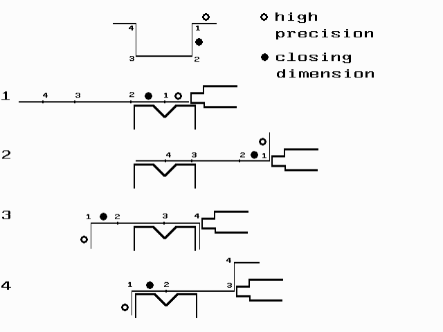
For optimal præcision bør linjestykker markeret med en åben cirkel placeres direkte mellem bagstoppen og dørstens centrum. Bemærk venligst, at at angive Høj- eller Lukkedimension-præcision for linjestykker kan forlænge produktionsprocessen på grund af mere komplekse systemberegninger. Desuden vil præcisionsparameteren have forrang i beregningsprocessen, hvis systemets "forlængelsesforhold foran" er indstillet til "overhold, hvis muligt".
Justering af bøjeegenskaber
Bøjninger er de centrale konstruktionsdele i tegninger til pladeprodukter, og DELEM DA-58T giver detaljerede indstillingsmuligheder for bøjningsegenskaber, herunder standardluftbøjninger, bump-bøjninger med stor radius og kantbøjninger. Hver bøjningstype har tilpasselige parametre, der kan tilpasses de faktiske fremstillingsforhold, og du kan justere egenskaberne ved at vælge den pågældende bøjning og åbne egenskabsmenuen.
Luftbøjning
Luftbøjning er den standardmæssige bøjningstype i pladebehandling, og programmering af en luftbøjning indebærer finjustering af linjelængder og vinkelværdier, indtil produktets form opfylder kravene. De vigtigste konfigurerbare parametre for luftbøjninger omfatter:

• Vinkel: Den målvinkel, hvormed plademetalet skal bøjes.
• Foretrukken radius: Den ønskede bøjningsradius, hvor pladetykkelsen som standard er den oprindelige værdi; en større foretrukken radius kan kræve matchende specialbøjeværktøjer.
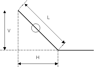
• Beregnet radius: Den faktiske bue-radius, som systemet genererer ud fra stylningsindstillingerne og de valgte værktøjer. Ved store beregnede radier kræves enten et dedikeret stempel, eller bumping-metoden kan bruges som alternativ. Det er afgørende at sikre, at bue-radius ikke overstiger længden af de tilstødende sider for at undgå behandlingskonflikter.
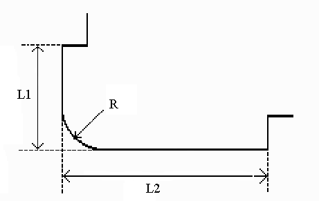
Når der programmeres linjelængder, der er forbundet til en bueradius, skal længderne af de to tilstødende sider (L1 og L2) være større end eller lig med bue-radius (R). En alternativ måde at oprette en luftbøjning på er at placere markøren ved flangens ende, hvor bøjningen er nødvendig, vælge Egenskaber og udfylde de yderligere parameterindstillinger i pop-up-vinduet.
Stor radius: Bumping
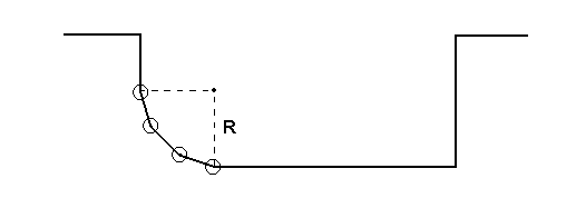
Hvis specialiserede værktøjer til bøjning med stor radius ikke er tilgængelige, kan DELEM DA-58T’s bumping-metode bruges til at skabe store radier ved at udføre en række små, successive luftbøjninger for at danne den ønskede krumme form.
For at bruge bumping-metoden skal du først vælge vinkeldefinitionen (enten systemets standardvinkel eller centralvinklen, som er 180 grader minus standardvinklen). Program derefter følgende nøgleparametre:
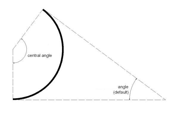
• Centralvinkel: Den supplerende vinkel til den ønskede bøjevinkel.
• Radius: Den ønskede store bøjeradius, hvor pladetykkelsen er den oprindelige standardværdi.
• Antal segmenter: Antallet af segmenter, hvori den store radius opdeles; det samlede antal bøjninger er lig antallet af segmenter plus én. Flere segmenter giver en strammere tolerance for den store radius, men kræver en mindre V-formåbning.
• Lige bumping-segmenter: Denne parameter styrer segmentstørrelsen. Når den aktiveres, sættes alle segmenter til samme størrelse; når den deaktiveres, bliver det første og sidste segment halvt så store som de midterste for en mere præcis bøjeeffekt, selvom dette kan komplicere valget af form. Hvis der opstår problemer med formtilpasning, giver systemet mulighed for genberegning med aktiverede lige segmenter.
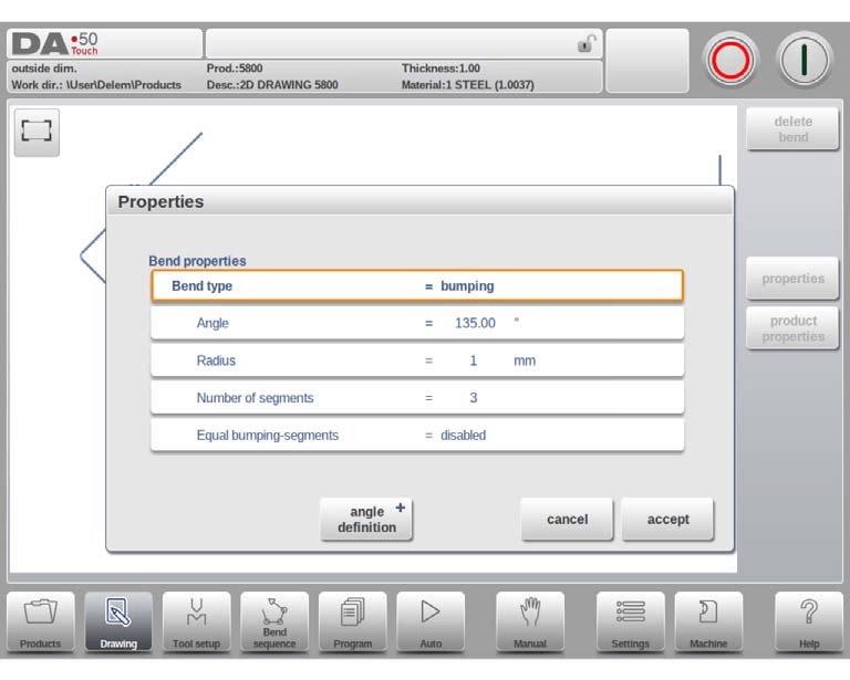
Programmeringstrinnene for en bumping-bøjning er som følger: Opret først en standardvinkel med tilstødende sider, vend derefter tilbage til vinklen, vælg Egenskaber og indstil Bøjningstype til Bumping. Indtast den ønskede radius, antallet af segmenter og segmentstørrelsesindstillingen, og systemet genererer den store radius i tegningen. Der vises også en besked med den mindste segmentlængde, hvilket er en afgørende reference for efterfølgende værktøjsvalg.
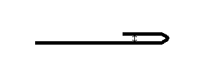
Hem-bøjninger
Hem-bøjninger er en specialiseret plade-metalbøjningsproces, der kombinerer en for-bøjning (en skarpvinklet standard luftbøjning) med en hemming-proces ved hjælp af dedikerede værktøjer.
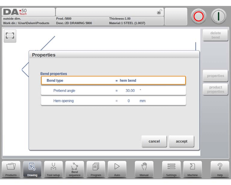
For at oprette en kantbøjning i DELEM DA-58T-tegningsgrænsefladen skal du først oprette en flange med en forudindstillet for-bøjningsvinkel. Derefter placerer du markøren på den ønskede bøjning og vælger Egenskaber for at justere de relevante parametre i det fremkommende vindue. Alternativt kan du placere markøren ved flangens ende, hvor kantbøjningen skal udføres, vælge Egenskaber og konfigurere de yderligere brugerdefinerede parametre, der vises.
Nøgleparametre, der kan konfigureres for kantbøjninger, omfatter:
• For-bøjningsvinkel: En spids vinkel (standardmæssigt 30 grader), som kan justeres efter de faktiske bearbejdningkrav.
• Kantåbning: Definerer afstanden mellem de to flanger efter kantbøjning og er en afgørende parameter til beregning af bjælkens position under kantbøjningsprocessen; standardværdien er indstillet via parameteren Standard kantåbning i systemets Indstillinger-modul.
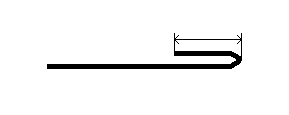
Den eneste nøgleparameter for siden ved kantbøjninger er Sidelængde, som henviser til længden af den flange, der skal kantbøjes, og som skal indstilles i overensstemmelse med produktets designkrav.
Ofte stillede spørgsmål (FAQ)
Q1: Hvad skal man gøre, hvis DELEM DA-58T-produkttegningen vises forkert?
Hvis tegningen viser fejl eller ikke svarer til den ønskede konstruktionsmæssige hensigt, skal alle indtastede parametre og systemindstillinger først dobbeltkontrolleres for at sikre korrektheden af mål, bøjenheder, radiusværdier og andre kerneoplysninger. Desuden skal det verificeres, at DELEM DA-58T-maskinen er korrekt kalibreret, da unøjagtig kalibrering også kan føre til fejl i tegningsvisning og efterfølgende bearbejdning.
Q2: Hvordan optimeres DELEM DA-58T-produkttegninger for højere effektivitet?
Optimer tegningseffektiviteten ved at organisere tegningslagene logisk, så brugergrænsefladen forbliver ren og overskuelig, hvilket gør det hurtigt at få adgang til og ændre parametre. Det anbefales også at opdatere DELEM DA-58T-systemsoftwaren regelmæssigt til den nyeste version, da officielle opdateringer ofte indeholder funktionsforbedringer og fejlrettelser, der forbedrer tegnings- og bearbejdningseffektiviteten.
Q3: Hvordan gemmes og eksporteres DELEM DA-58T-produkttegninger korrekt?
Brug systemets "Gem som"-funktion til at gemme og eksportere tegningsfiler, og vælg et filformat, der svarer til dine efterfølgende applikationsbehov for tværsystemkompatibilitet. De mest almindeligt anvendte formater er DXF, DWG og PDF, som er fuldt kompatible med de fleste almindelige CAD-programmer og letter filudveksling og sekundær redigering.
Konklusion
At mestre processen med at oprette produkttegninger med DELEM DA-58T-systemet kræver en forståelse af den logiske rækkefølge i de operative trin: fra den grundlæggende opsætning af generelle produktegenskaber, via den detaljerede oprettelse af 2D-produkttegninger til den præcise konfiguration af linje- og bøjeegenskaber. Hvert trin kræver streng overholdelse af reglerne for parameterindstilling og operationelle detaljer for at sikre nøjagtigheden og udførligheden af den endelige tegning.
Ved at følge de standardiserede trin og bedste praksis, der er beskrevet i denne vejledning, kan operatører betydeligt forbedre deres færdigheder i at oprette DELEM DA-58T-produkttegninger, sikre konsistensen mellem tegningsdesign og den faktiske pladebehandling samt maksimere systemets ydeevne i metalbearbejdning. For yderligere professionel vejledning eller til løsning af komplekse driftsproblemer er du velkommen til at kontakte det officielle tekniske supportteam, som leverer skræddersyede løsninger og ekspertvejledning. Du kan også gennemgå systemets officielle dokumentationsbibliotek for mere detaljerede driftstips og optimeringsstrategier, der forbedrer dine færdigheder i at anvende DELEM DA-58T.

