


Овладяване на инструмента за създаване на продуктови чертежи DELEM DA-69S: Пълно ръководство за работа
Съдържание
1. Обща информация за чертежа на продукта DELEM DA-69S
2. Основни настройки на атрибутите на продукта
3. Добавяне на анотации и прикачени документи
4. Създаване на 2D чертежи на продукти
5. Овладяване на настройките на свойствата на линиите и извивките
5.1 Свойства на линиите
5.2 Свойства на извивките
6. Етикети за извивки (ексклузивно за серията DA-6xTe)
7. Маркиране на повърхности или линии за огъване
8. Указване на страната на фолиото
9. Използване на напреднали функции за измерване
10. Управление на променливи размери на продукта
10.1 Променливи свойства на линиите
11. Редактиране на 3D чертежи
11.1 Общ преглед на редактирането на 3D чертежи
11.2 Редактиране и въртене на моделите на продуктите
11.3 Подробни операции по редактиране на 3D чертежи
12. Често задавани въпроси (ЧЗВ)
13. Заключение
Независимо дали сте новак в индустрията за обработка на метали или опитен професионалист, овладяването на инструмента за създаване на чертежи DELEM DA-69S е решаващ фактор за повишаване на ефективността на производството и точността на проектите ви. Това ръководство ще ви запознае подробно с всички основни функции и операционни техники на системата за създаване на чертежи DELEM DA-69S — от базовата настройка на атрибутите на продукта до напредналото редактиране на 3D модели. В края на това ръководство ще притежавате изчерпателно разбиране на начина, по който да използвате този мощен инструмент в пълния му потенциал за всичките си проекти в областта на металообработката.
1. Обща информация за чертежа на продукта DELEM DA-69S
Основата за ефективното използване на инструмента за създаване на чертежи DELEM DA-69S е разбирането как да се конфигурират и модифицират основните атрибути на продукта, което директно влияе върху ефективността и точността на последващата работа по създаване на чертежи.
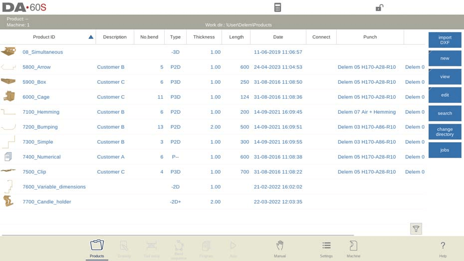
За да редактирате съществуващ чертеж на продукт, просто намерете целевия продукт в Библиотеката на продукти и натиснете бутона „Чертеж“. За създаване на нов чертеж на продукт изберете „Нов продукт“ и системата автоматично ще покаже интерфейса за основна конфигурация на атрибутите на продукта — това е отправната точка за цялата работа по чертане и всички настройки на атрибутите трябва да бъдат завършени преди започване на самия процес на чертане.
2. Основни настройки на атрибутите на продукта
Интерфейсът за основни атрибути на продукта съдържа всички ключови параметри за чертането на продукта и всяка настройка трябва да е точна и адаптирана към реалните производствени изисквания:
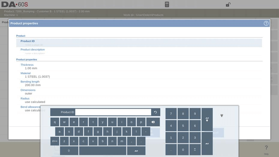
• Идентификатор на продукта и описание: Въведете уникален идентификатор на продукта и описателен текст, като максималният брой символи за всеки от тях е 25. Уверете се, че идентификаторът е единствен, освен ако не сте решили намерено да презапишете съществуващ файл на продукт.
• Дебелина: Задайте точната дебелина на листовия метал, използван за продукта.
• Избор на материал: Изберете подходящия тип материал от четирите предварително програмирани опции в системата, за да съответства на материалите, използвани при действителното производство.
• Дължина на огъването: Задайте дължината на огъването на продукта по Z-ос, който е ключов параметър за проектиране на процеса на огъване.
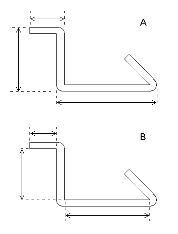
• Референтни размери: Изберете между външни (A) или вътрешни (B) размери като подразбирана референтна точка за нови страни или повърхности чрез опцията „Подразбирани размери“.
• Настройка на радиуса: Радиусът на огъване на продукта зависи от избраните инструменти; за този параметър можете да изберете либо „изчислен“ (автоматично изчисление от системата), либо „програмиран“ (персонализирано предварително зададени стойности).
• Поправка за огъване: Налични са два варианта — „изчислена“ (прилагане на ексклузивната формула на DELEM) или „програмирана“ (персонализирани предварително зададени стойности), които влияят върху точността на процеса на огъване.
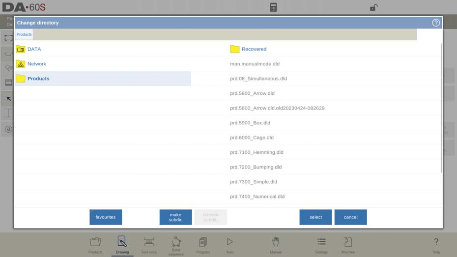
За да промените активната директория за чертежи на продукти, изберете „Запазване като“ и след това „Промяна на директорията“; системата автоматично ще копира текущия файл на продукта в новоизбраната директория, за лесно управление на файловете.
3. Добавяне на анотации и прикачени документи
Добавянето на подробни анотации и съответстващи документи към чертежите на продукти гарантира ясна комуникация на изискванията за проектиране и удобно справочна информация за последващото производство и инспекция:
1. Редактиране на анотации: Кликнете върху бутона „Редактиране на бележки“ и ще се отвори нов прозорец за редактиране, като оставащият брой налични символи се показва на екранната клавиатура за реално време по време на въвеждане на текст.
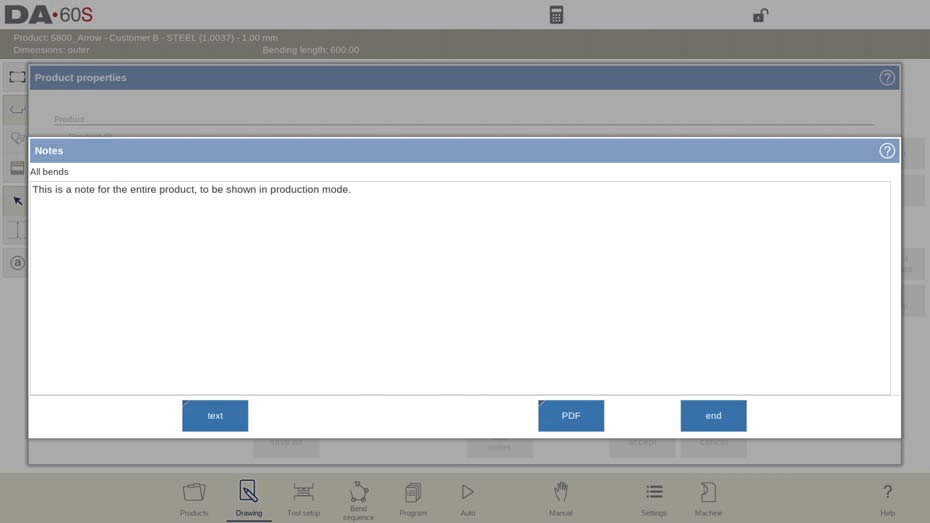
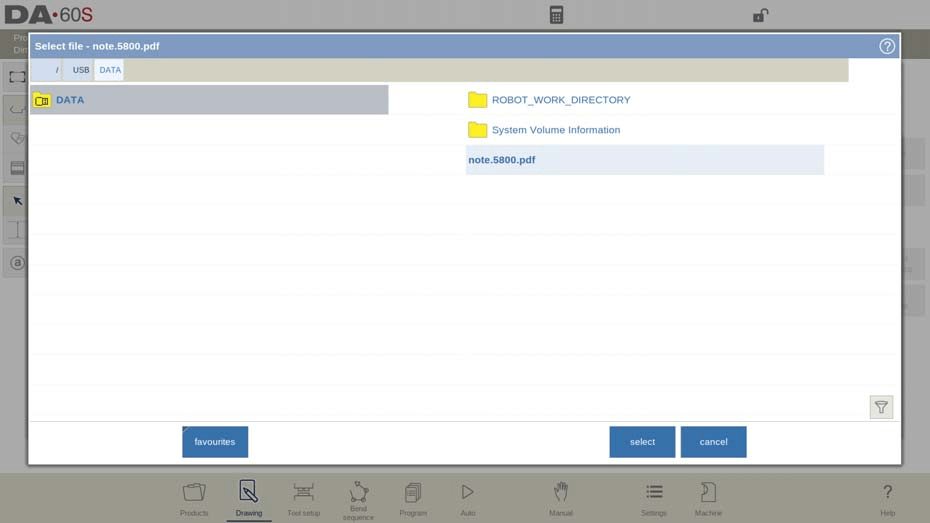
2. Прикачване на PDF файлове: Докоснете „Прикачване на PDF“, прегледайте директорията с файлове, за да изберете целевия PDF документ, и системата автоматично ще го прикачи към текущия файл на продукта.
3. Автоматично показване за прикачени само PDF файлове: Ако е прикачен само PDF файл, без текстови бележки, PDF файлът ще се отвори и покаже автоматично при натискане на индикатора „Бележки“ в автоматичен режим, което опростява процеса на справка.
4. Създаване на 2D чертежи на продукти
След завършване на основната конфигурация на атрибутите на продукта системата ще зареди интерфейса за 2D чертеж, където горният ред показва ключова информация като идентификационен номер на продукта, описание на продукта и референтни размери (вътрешни/външни). Създаването на точен 2D чертеж на продукта следва тези интуитивни стъпки, проектирани за ефективност и точност:
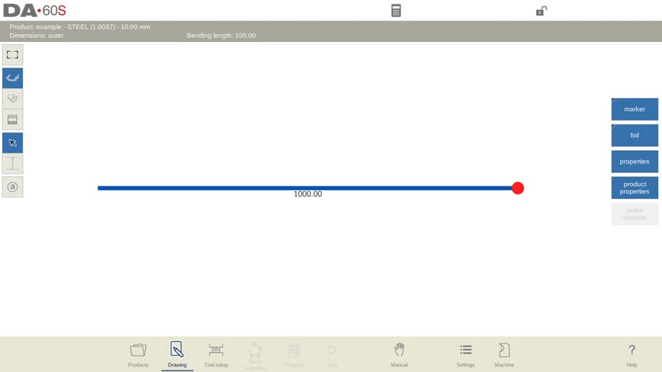
1. Набросък на профила: Използвайте сензорния екран, за да начертаете ръчно основния профил на продукта с пръстите си. Този интуитивен режим за набросък ви позволява бързо да очертаете общата форма на продукта, без да въвеждате точни размери на този етап.
2. Калибриране на размерите: След като сте начертали основния профил, въведете действителните размери на продукта чрез екранната клавиатура, за да замените приблизителните размери от набросъка.
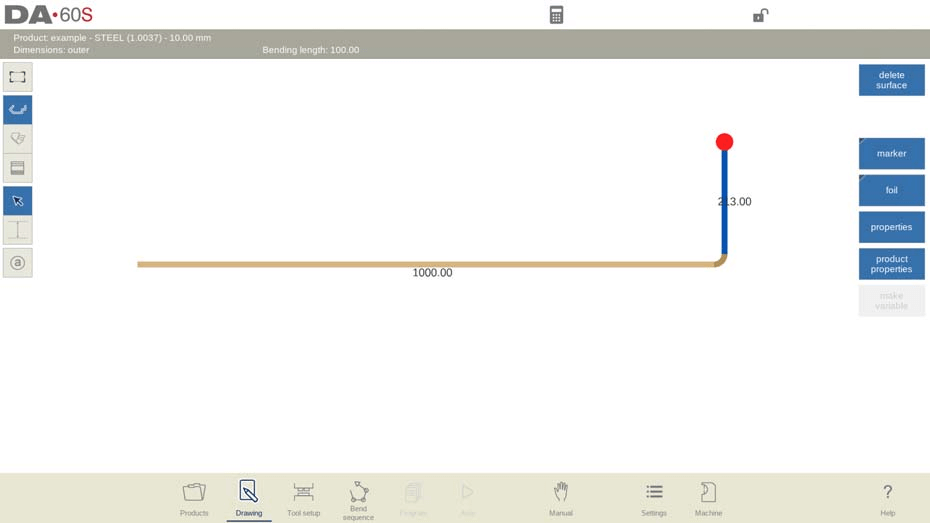
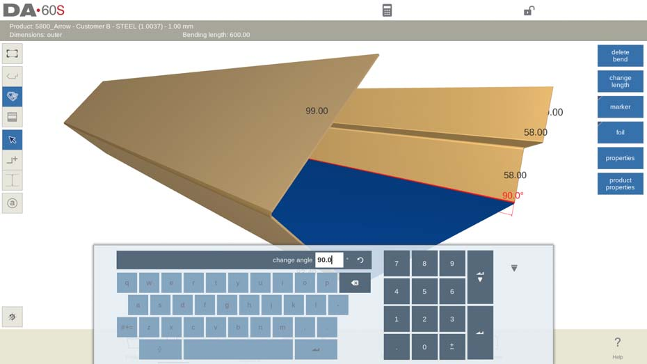
3. Въвеждане на ъгъл и дължина: Въведете директно ъгъла на извиване за всяка извивка и съответната дължина на страната чрез клавиатурата и потвърдете всеки вход с бутона Enter, за да гарантирате точността на параметрите.
4. Настройка на атрибутите: Променяйте общите данни за продукта по всяко време чрез бутона „Свойства на продукта“ и прецизно настройте отделни ъгли или линии чрез бутона „Свойства“ — активните елементи в интерфейса се подчертават, за да се осигури лесно идентифициране и редактиране.
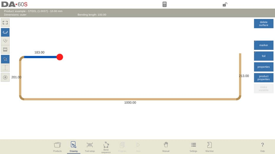
5. Разширено програмиране: В графичния режим системата поддържа проектирането на продукти с до 99 извивки. След като завършите 2D чертежа, преминете към стъпките „Настройка на инструментите“ и „Последователност на извиването“, за да завършите процеса на предварително производствено програмиране.
Този поетапен процес гарантира, че 2D проектирането на продукти с DELEM DA-69S е както точно, така и ефективно, като успешно решава типичните проектирани и операционни предизвикателства за потребителите.
5. Овладяване на настройките на свойствата на линиите и извивките
Точният контрол върху свойствата на линиите и извивките е основата за създаване на точни чертежи на продукти и директно определя възможността и точността на последващия процес на гънене.
5.1 Свойства на линиите
Свойствата на линиите могат да се променят и оптимизират по всяко време, за да отговарят на изискванията за проектиране, като системата предоставя гъвкави инструменти за настройка:
1. Промяна на основните спецификации: Поставете курсора върху целевата линия на продукта и изберете „Свойства“, за да отворите прозореца за редактиране на параметри и да настроите основните спецификации на линията.
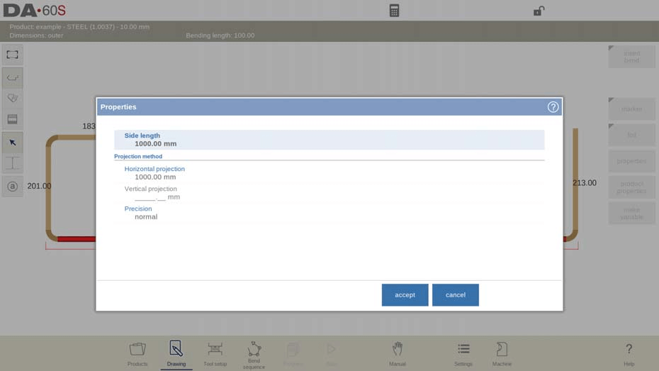
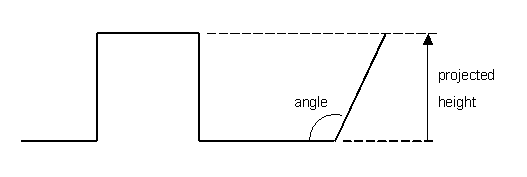
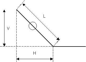
2. Настройка на проекция: В прозореца за свойства на линията задайте хоризонтална и вертикална проекция, за да създадете диагонални линии без ръчно изчисляване на точните дължини — това е функция, спестяваща време при проектирането на сложни профили. Системата използва L (нормална дължина), V (вертикална проектирана дължина) и H (хоризонтална проектирана дължина) за точна настройка на дължината на линията и ще изведе предупреждение, ако зададените параметри за проекция не са възможни.
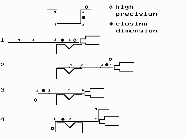
3. Избор на параметри за прецизност: Налични са три опции за прецизност, които отговарят на различните производствени изисквания:
○ Нормална: Стандартна точност, подходяща за общи производствени сценарии.
○ Висока: Максимизира точността на изчисленията за последователността на огъване, идеална за производство на високоточни продукти.
○ Затварящи размери: Гарантира, че всички допуски за разстояния между линиите отговарят на проектните стандарти, приложими за продукти със строги размерни изисквания.
Забележка: Линиите с интервали, отбелязани с отворен кръг, трябва по възможност да се позиционират директно между задната упорна плоча и центъра на матрицата, за да се постигнат оптимални производствени резултати.
Основни бележки: Задаването на интервали между линиите с висока прецизност или затварящи размери може да увеличи времето за изчисление при производството. Ако е зададено разширение напред с опция „при възможност“, параметърът за прецизност ще има предимство в изчислителната логика на системата.
Бързо редактиране на линии и огъвания: Въз основа на позицията на курсора можете лесно да вмъквате или изтривате огъвания и линии:
• Изтриване на крайна линия: Поставете курсора върху крайна линия, за да изтриете целия сегмент от линията.
• Вмъкване на завой: Поставете курсора върху сегмент от линия, който не е крайна линия, за да вмъкнете нов завой; системата автоматично копира дължината на страната на оригиналния сегмент.
• Изтриване на завой: Поставете курсора върху ъгловия маркер на завоя, за да премахнете този конкретен завой.
5.2 Свойства на извивките
Настройките на свойствата на завоя са адаптирани според различните изисквания към процеса на гънене, а DELEM DA-69S поддържа разнообразни типове гънене, за да решава често срещани производствени предизвикателства и да гарантира точност при гъненето. По-долу е подробният метод за настройка на всеки основен тип гънене:
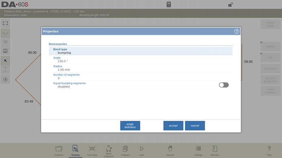
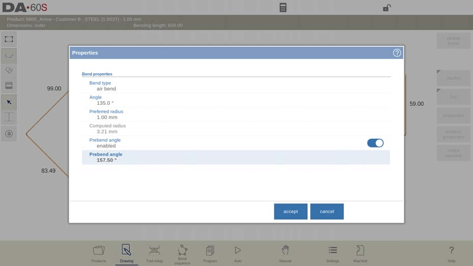
1. Настройка на гънене във въздух: Първо графично програмирайте контурa на продукта, като въведете дължините на линиите, ъгловите стойности и последващите дължини на линиите, докато се постигне желаната форма. Изберете „Свойства“, за да зададете типа гънене като „Гънене във въздух“, след което определете целевия ъгъл и предпочитания радиус. Това е основната настройка на типа гънене и е задължителна за конфигуриране на стандартни и персонализирани свойства на гъненето.

2. Метод на стъпково огъване за големи радиуси: Ако не разполагате с матрица с голям радиус, изберете „Стъпково огъване“ като тип огъване. Задайте ключовите параметри, включително централния ъгъл, целевия радиус и броя на сегментите, след което програмирайте тези настройки последователно. Системата постига непрекъснат голям радиус чрез множество последователни леки огъвания — практично решение при ограничени инструментални условия.
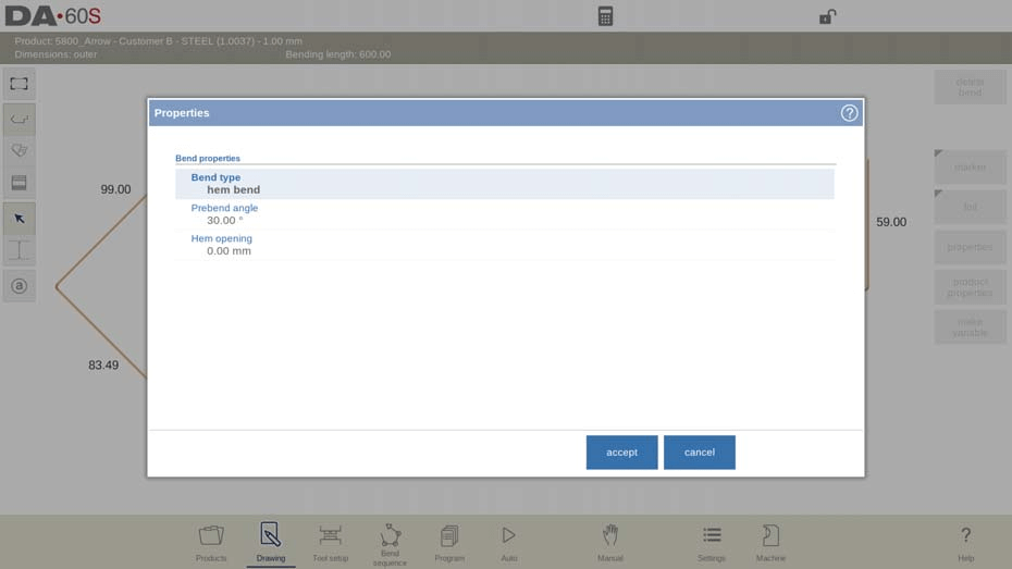
3. Дефиниране на огъване с подгъване (хем): При огъване с подгъване първо задайте ъгъла на предварително огъване. Преместете курсора до края на целевата фланца, изберете „Свойства“ и въведете стойностите за ъгъла на предварително огъване и отвора на подгъването — тези параметри са критични за точното изчисляване от системата на положението на гредата по време на производствения процес.
4. Двуетапно огъване: За по-голям контрол върху процеса на огъване и намаляване на риска от колизии програмирайте огъване с параметри за предварително огъване. Този двуетапен процес разделя огъването на етап на предварително огъване и етап на окончателно огъване, като системата изчислява оптималната последователност за двете стъпки, за да гарантира точност и безопасност.
5. Временно извиване: Вмъкване на временни извивки, за да се избегнат колизии по време на процеса на извиване, със следните ключови характеристики:
○ Временната извивка може да се разгъне обратно в равна страна след приключване на производственото планиране.
○ Използвайте функцията за вмъкване на извивка, за да добавите временни извивки (включително настройки за предварително извиване) към последователността от извивки.
○ Системата напълно интегрира временни извивки в последователността от извивки,
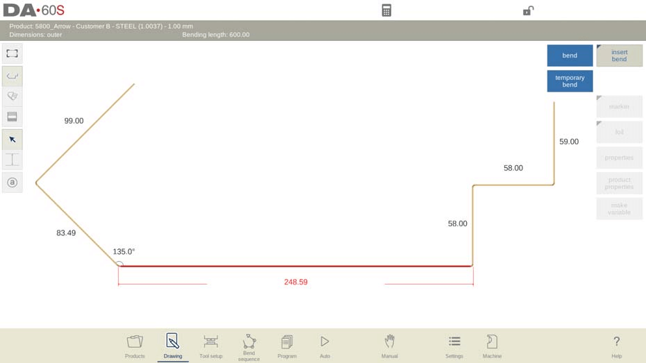
за да гарантира точността на избягването на колизии и проектирането на процеса.
6. Етикети за извивки (ексклузивно за серията DA-6xTe)
Етикетите за извивки са практически функция за проследяване и управление на всяка извивка в производствения процес, а DELEM DA-69S (DA-6xTe) предлага гъвкаво и интуитивно използване на етикети, което опростява управлението на последователността от извивки:
1. Многофункционален достъп: Етикетите за извивки са налични не само в режима „Последователност от извивки“, но и в графичната визуализация на режими „Чертеж“ и „Автоматичен“, което позволява на операторите да проследяват извивките през целия процес на проектиране и производствено планиране.
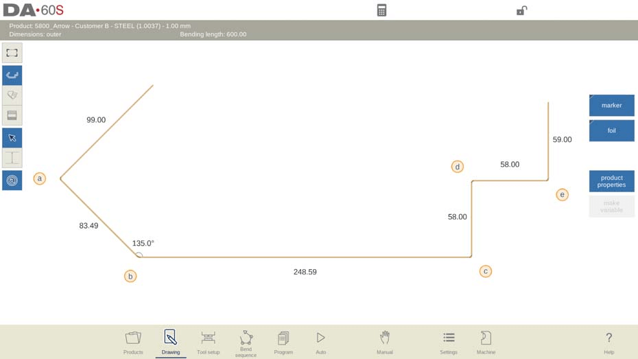
2. Автоматично азбучно маркиране: След активиране системата автоматично присвоява уникален азбучен идентификатор на всяка линия на огъване, което позволява на операторите бързо да идентифицират конкретни огъвания и да опростят настройката на последователността на огъване и производствените операции за продукта.
3. Активиране с едно натискане: Просто докоснете бутона за изглед на етикетите за огъване в интерфейса на DELEM DA-69S, за да активирате етикетите за огъване; малки етикети автоматично се появяват при всяка линия на огъване, осигурявайки ясно визуално ръководство.
7. Маркиране на повърхности или линии за огъване
Маркирането на ключови повърхности или линии на огъване върху чертежите на продукта подобрява идентифицирането на критичните конструктивни елементи, а DELEM DA-69S предоставя прост и гъвкав инструмент за маркиране със следните стъпки за работа:
1. Задаване на маркер: Изберете целевото положение на чертежа на продукта, където е необходим маркерът; цилиндричен етикет автоматично се появява на това място; маркерът може да бъде преместен по всяко време чрез влачене.
2. Автоматично показване в автоматичен режим: Маркерите се показват автоматично в автоматичния режим, което гарантира, че операторите могат бързо да идентифицират ключовите позиции по време на планирането на производството.
3. Обръщане на цветовете на маркера: Разменете горните и долните цветове на маркера, за да отговарят на различните визуални изисквания и настройки на фона на чертежа.
4. Премахване на маркера: Лесно премахнете маркера с един щракване, за да почистите интерфейса на чертежа, когато вече не е необходим.
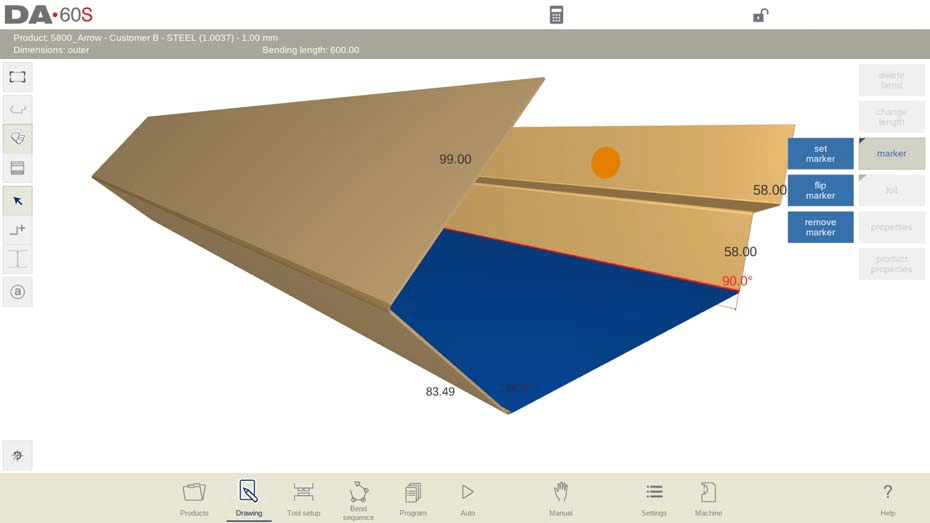
Този инструмент за маркиране ефективно решава проблема с идентифицирането на критичните елементи на дизайна и осигурява яснота и точност в комуникацията относно продуктния дизайн и производството.
8. Указване на страната на фолиото
Подчертаването на фолиевата страна върху чертежите на продуктите предотвратява неправилното разположение на разгънатия листов метал по време на производството — ключов детайл за осигуряване на производствена точност. Стъпките за указване на фолиевата страна са прости и интуитивни:
1. Прилагане на фолио-индикация: Използвайте функцията за прилагане на фолио, за да добавите маркировка на страната с фолио, като системата автоматично променя цвета на едната страна на продукта, за да се отличава ясно страната с фолио.
2. Обръщане на страната с фолио: Ако първоначалната маркировка на страната с фолио не е в желаното положение, използвайте функцията за обръщане на фолиото, за да размените горната и долната част на маркираната страна с фолио, за по-точно позициониране.
3. Премахване на фолио-индикация: Използвайте функцията за премахване на фолио, за да изчистите маркировката на страната с фолио по всяко време и да коригирате чертежа според нуждите.
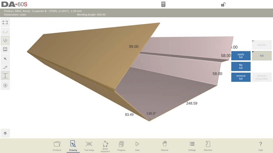
Тази функция ефективно решава често срещаните проблеми при визуализацията на продукти и гарантира правилното позициониране на листовия метал по време на процесите на разгъване и огъване.
9. Използване на напреднали функции за измерване
DELEM DA-69S е оснастен с мощни напреднали функции за измерване в графичния си интерфейс за чертане, които позволяват прецизно измерване на развитите дължини в множество посоки — тези функции са от критично значение за проверка на проектните размери и оптимизация на производствения процес. Ето как да ги използвате ефективно:
1. Измерване на разгърнатите дължини: Навигирайте до графичния чертежен интерфейс и използвайте функцията за измерване, за да изберете две противоположни линии в една и съща посока; системата автоматично ще изчисли разгърнатата дължина и ще покаже размерна линия върху чертежа за ясна визуална ориентация.
2. Включване на изчисленото отклонение при огъване: За по-висока точност на измерванията системата позволява включването на автоматично изчисленото отклонение при огъване в измерените дължини. Забележка: Тази функция е достъпна само след избор на инструмент и завършване на последователността на огъването — уверете се, че тези предварителни условия са изпълнени, за да използвате тази функция.
3. Използване на функцията „Промяна на дължината“:
○ Активирайте режима за измерване, за да получите достъп до функцията „Промяна на дължината“, която позволява прецизна корекция на хоризонталните или вертикалните натрупани дължини.
○ В режима за измерване бутони за избор на сегмент ще се появят до всеки линеен сегмент; изберете сегмента, чиято дължина трябва да бъде коригирана.
○ Докоснете активната линия за измерване, за да изберете хоризонтална или вертикална проекция, след което въведете желаната стойност за корекция, за прецизна промяна на дължината.
Всеки етап от напредналите функции за измерване е проектиран така, че да решава конкретни предизвикателства, с които потребителите се сблъскват при измерването, като по този начин елиминира несигурността в процеса на проверка на размерите и подобрява точността и ефективността на продуктовото проектиране.
10. Управление на променливи размери на продукта
DELEM DA-69S поддържа гъвкава корекция на променливи размери на продукта, като позволява моментално разтягане или свиване на определени линейни сегменти, за да се адаптира към различни производствени и проектни изисквания. По-долу е опростено ръководство за управление на променливи размери и конфигуриране на свойствата на променливи линии:
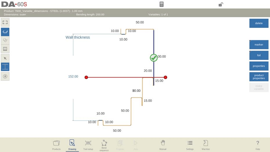
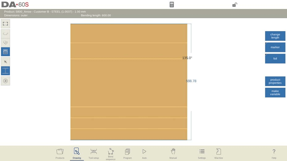
Основни операционни стъпки
1. Програмиране на променливи линии: Променете размерите на продукта, като добавите променливи линии, които позволяват разтягане или свиване в посочената позиция на линията. Коригирайте дължината на референтната страна, за да генерирате отместване, което системата ще приложи към всички пресичащи се линейни сегменти.
2. Режим на реално време в автоматичния режим: В автоматичния режим промените в дължината на променливата линия се въвеждат директно по време на планирането на производството; системата автоматично коригира всички пресичащи се страни чрез именуваната(ите) променлива(и), което гарантира безпроблемни и последователни актуализации на размерите.
3. Проверка преди производството: След затваряне на диалоговия прозорец „Променливи“ в автоматичния режим проверете модела на продукта за възможни колизии; ако не се открият проблеми, програмата е готова за производство.
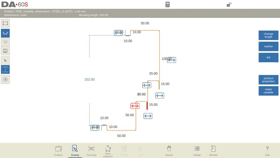
4. Вмъкване и настройка на променливи линии: Докоснете бутона „Направи променлива“, за да вмъкнете променлива линия въз основа на съществуващите дължини на страните или измерените размери. Променяйте позицията на линията, за да приложите разтягане/свиване към конкретни сегменти; системата използва цветови и символни визуални индикатори, за да насочва процеса на настройка.
5. Управление на неактивните променливи: Изтриването на референтната страна на линията на променлива прави линията неактивна, което системата отбелязва с червен цвят в автоматичния режим. Забележка: Уверете се, че всички пресичащи се сегменти остават перпендикулярни за ефективното използване на линиите на променливи.
6. Съвместимост между 2D/3D изгледи: Добавяйте линии на променливи както в 2D, така и в разгънатия изглед за 2D продукти; за 3D продукти линиите на променливи могат да се добавят само в разгънатия изглед.
10.1 Променливи свойства на линиите
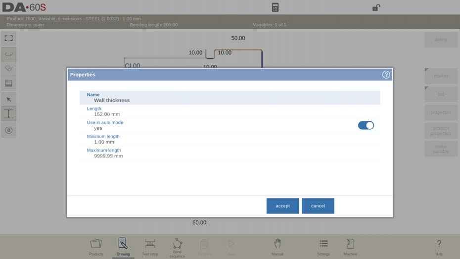
След вмъкване на линия на променлива изберете линията и докоснете „Свойства“, за да отворите прозореца за конфигуриране на параметрите. Основните атрибути на линията на променлива са следните:
• Име: Задайте уникално потребителско име на линията на променлива за лесна идентификация и управление.
• Дължина: Задайте дължината на референтната страна на линията на променлива – основната стойност за последващото разтягане/свиване.
• Използване в автоматичния режим: Изберете „Да“ или „Не“, за да посочите дали линията на променлива е регулируема в автоматичния режим.
• Минимална/максимална дължина: Задайте горната и долна граница за дължината на променливата линия, за да се предотвратят невалидни корекции по време на производствено планиране в автоматичен режим.
Овладяването на управлението на променливи размери ви позволява бързо да се адаптирате към променящите се изисквания за проектиране и производство, ефективно решавайки предизвикателствата, свързани с клиентската персонализация, и оптимизирайки използването на инструмента DELEM DA-69S.
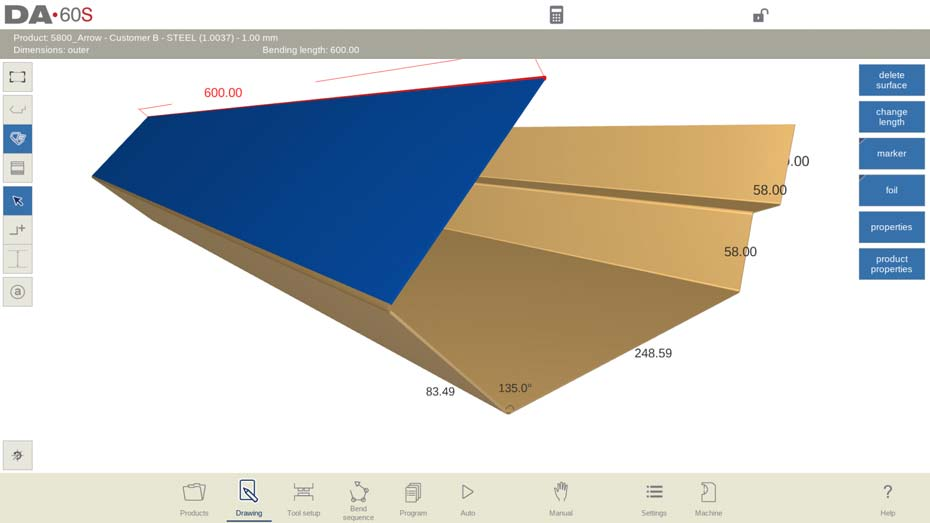
11. Редактиране на 3D чертежи
DELEM DA-69S улеснява създаването и редактирането на 3D чертежи на продукти чрез преобразуване на 2D профили в 3D модели, като предоставя пълен набор от инструменти за редактиране на повърхности, ъгли и дължини. Системата поддържа превключване между 2D, 3D и разгънати 3D изгледи, като командните икони на интерфейса осигуряват превключване между изгледите с един клик:
• 2D изглед: Показва продукта като 2D профил (първоначалният проектен изглед).
• 3D изглед: Визуализира продукта като 3D твърдо тяло, като дълбочината на повърхностите се определя от първоначално програмираната дължина на огъване.
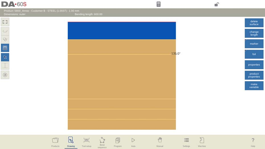
• 3D разгънат изглед: Показва 3D продукта като плоска листова метална заготовка (състоянието преди огъване), което е критично за производството и рязането на материала.
11.1 Общ преглед на редактирането на 3D чертежи
3D чертеж на продукта се създава чрез преобразуване на 2D профил, а системата използва различни визуални индикатори, за да опрости редактирането: активната повърхност е подчертана с уникален цвят, а курсорът, маркиращ избрания огъв, се показва в червено. Основните операции за 3D редактиране включват:
1. Редактиране на чертежа чрез добавяне/премахване на повърхности и коригиране на свойствата на страни/ъгли, като допълнителни функции за свойства, специфични за отделни повърхности, са достъпни директно в интерфейса за 3D чертеж.
2. Превключване между режимите „Избор“ и „Добавяне на повърхност“ според различните нужди от редактиране:
○ Режим „Избор“: Докоснете бутонът със стрелка, за да изберете и редактирате съществуващи линии на огъване и повърхности.
○ Режим „Добавяне на повърхност“: Докоснете символа „+“ до продукта, за да добавите нови повърхности към отворените страни на съществуващия 3D модел.
3. Добавяне на повърхности с точност: Поставете курсора върху свободната страна на съществуваща повърхност, докоснете целевата позиция до линията на извивката и системата ще разтегли новата повърхност до тази позиция. Настройте ъгъла и височината за по-голяма точност; по подразбиране системата използва стъпки от 45 градуса за бърза корекция; при нужда уточнете точните стойности чрез клавиатурата.
4. Прецизни корекции: Променяйте ъглите и дължините на страните, като въвеждате точните стойности чрез клавиатурата или влачите курсора (курсорът се прихваща на стъпки от 5 градуса, когато е върху крайната линия на продукта). По подразбиране повърхностите са правоъгълни и могат да се модифицират, за да съответстват на персонализирани форми на дизайн.
Докоснете бутона „Преглед“, за да превключвате по всяко време между 2D, 3D и разгънат 3D режим на гледане, за всеобхватна проверка на дизайна.
11.2 Редактиране и въртене на моделите на продуктите
Добавянето на нова повърхност към свободния ръб на 3D модел на продукт е основна операция за 3D редактиране, която се извършва чрез следния поетапен процес:
1. Изберете свободен ръб: Докоснете свободния ръб на 3D продукта, където трябва да се добави новата повърхност.
2. Активирайте режима за добавяне на повърхност: Превключете в режима за добавяне на повърхност чрез съответното бутонче на интерфейса.
3. Задайте крайната точка на повърхността: Дефинирайте крайната точка на новата повърхност, след което въведете точния ъгъл и дължина на повърхността чрез екранната клавиатура за прецизно позициониране (от критично значение за съответствие с изискванията на дизайна).
Полезни функции за навигация (достъпни за всички операции по редактиране на 3D модели):
• Приспособяване към изгледа: Автоматично мащабира 3D модела на продукта така, че да се побере целият на екрана за пълен преглед.
• Възстановяване на изгледа: Връща изгледа на модела (завъртане и мащабиране) към системните му начални настройки — идеално за повторно ориентиране на модела след сложни завъртания/мащабиране.
11.3 Подробни операции по редактиране на 3D чертежи
3D чертожният инструмент на DELEM DA-69S се отличава с възможността си да управлява сложни продуктови дизайните с множество повърхности (всички започващи от базова повърхност), като осигурява мощни възможности за редактиране при добавяне, изтриване и преформиране на повърхности (квадрати, правоъгълници и други четириъгълници). По-долу са подробно описани оперативните насоки за решаване на конкретни дизайн предизвикателства:
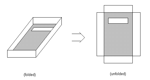
1. Добавяне на повърхност: Свържете нови повърхности със свободните страни на съществуващи повърхности, като докоснете крайните точки или въведете точни ъгли и дължини, за да създадете нови правоъгълни повърхности. Ключова функция: всяка повърхност може да включва контури (напр. отвори), без да се използва допълнителен чертожен инструмент за тяхното вмъкване.
2. Изтриване на повърхност: Повърхност може да бъде изтрита само ако е свързана с точно една друга повърхност и не е базовата повърхност (основната повърхност на 3D модела) — това предотвратява случайно изтриване на критични структури на модела.
3. Промяна на дължината на страната: Изберете целевата страна, за да видите текущата ѝ дължина; ще се отвори изскачащ прозорец за настройка. Изберете дали да промените дължината от двете страни или само от едната страна и въведете положителни/отрицателни стойности, за да удължите или скъсите страната.
Практичен пример за коригиране на дължината на страната (текуща дължина на страната = 100 мм):
• Равномерна корекция: Маркирайте цялата страна и въведете 60 мм — системата намалява страната еднакво от двете страни, като запазва симетрията на дизайна.
• Корекция само на лявата страна: Използвайте функцията „Следваща част“, за да изберете само лявата част от страната, и въведете 60 мм — намалява се само лявата страна, което решава задачи с асиметричен дизайн.
• Корекция само на дясната страна: Използвайте функцията „Следваща част“, за да изберете само дясната част и въведете 60 мм — намалява се само дясната страна, за целенасочени корекции на дизайна.
• Алтернатива: Въвеждането на -40 мм постига същото намаляване на дължината (окончателна дължина 60 мм), като удължи страната в противоположна посока, което демонстрира гъвкавите възможности за коригиране на системата.
Правила за промяна на дължините на страни (за избягване на грешки в модела):
• Дължината на линията на огъване може да се промени само ако промяната не засяга други повърхности или огъвания в 3D модела.
• Не могат да се правят корекции, ако и двата края на една страна са част от линия на огъване и са подравнени по посоката на тази линия.
Примери за възможност за коригиране на страни:
• Пример 1: Страна 1 (и двата края свободни) → удължаване/скъсяване в двете посоки; Страни 2 и 4 (по един край свързани с линия на огъване) → може да се коригира само свободният край; Страна 3 (и двата края свободни) → удължаване/скъсяване в двете посоки.
• Пример 2: Страни 1 и 3 (по един край свързани с линия на огъване) → може да се коригира само свободният край; Страна 2 (и двата края свързани с линии на огъване) → корекция не е разрешена; Страни 4, 5 и 6 (и двата края свободни) → удължаване/скъсяване в двете посоки.
Създаване на специални форми (напр. шестоъгълник): Започнете с два правоъгълника под ъгъл 180°, след което използвайте или несиметрично скъсяване (скъсете всяка страна до 75 мм), или симетрично скъсяване (скъсете всяка страна до 50 мм), за да получите идеален шестоъгълник. Системата поддържа създаването на различни персонализирани специални форми чрез просто регулиране на дължините на страните.
Ключов съвет за 3D редактиране: Позиционирайте курсора в ъгъла на повърхността при задаване на нова дължина, за да постигнете прецизност. Дори за 3D продукти с извивки в една посока основните корекции на размерите са лесни — особено непосредствено след конвертиране на 2D профил в 3D модел. Използвайте диалоговия прозорец за промяна на дължината заедно с функционалните клавиши за дълбочина на профила и дължина на повърхността, за да променяте бързо общия размер на продукта.
4. Промяна на ъгъла: Свободно регулирайте ъгъла между свързаните повърхности в диапазона от –180° до 180°. Наблюдавайте промените в модела в относителен мащаб по време на регулиране, за да избегнете колизии между повърхностите — това е критична стъпка при проектирането на сложни 3D модели.
12. Често задавани въпроси (ЧЗВ)
В1: Мога ли да импортирам съществуващи проекти в системата за продуктови чертежи DELEM DA-69S?
О: Да. Системата поддържа импортиране на файлове с проекти в съвместими формати. За пълен списък на поддържаните типове файлове и подробни стъпки за импортиране, вижте официалното ръководство за употреба на DELEM DA-69S и следвайте процеса за конфигуриране в настройките на системата.
В2: Какво трябва да направя, ако се сблъскам с грешки при използването на модула за продуктови чертежи DELEM DA-69S?
О: Първо, уверете се, че софтуерът на машината е актуализиран до най-новата версия. За често срещани грешки вижте раздела „Отстраняване на неизправности“ в ръководството за употреба на DELEM DA-69S, за да намерите решения. Ако проблемът продължи и не може да бъде решен, свържете се с официалния екип за клиентска поддръжка, за да получите професионална помощ.
В3: Предоставя се ли обучение за използване на функциите за продуктови чертежи на DELEM DA-69S?
А: Да. За инструмента за създаване на продуктови чертежи DELEM DA-69S са налични специализирани учебни сесии и учебни ресурси. Можете да се обърнете към доставчика на вашето оборудване за обучение на място или онлайн, или да използвате официалните онлайн ръководства и видеоуроци за самостоятелно обучение.
Тези отговори обхващат най-често задаваните от потребителите въпроси и помагат за разрешаване на операционни несигурности, като по този начин подобряват общата ефективност при използването на инструмента.
13. Заключение
Овладяването на инструмента за създаване на продуктови чертежи DELEM DA-69S се свежда до три основни стъпки: разбиране на целия му набор от функции, свободно ориентиране в неговия интуитивен интерфейс и прилагане на операционните техники, описани в настоящото ръководство, за оптимизиране на процесите ви за производство на метални изделия. Чрез усвояване на тези умения не само ще повишите ефективността си при проектиране и производство, но и ще гарантирате безпрецедентна точност във всеки проект по металообработка, който предприемате.
Като следваща стъпка ви насърчаваме да проучите официалната библиотека с ресурси на DELEM за по-задълбочени технически информация и напреднали оперативни съвети. Ако имате нужда от персонализирана поддръжка или конкретни технически въпроси, нашият експертен екип винаги е на ваше разположение, за да ви помогне. За по-изчерпателно ръководство относно DELEM DA-69S и други свързани инструменти, обърнете се към нашата официална документация или се свържете директно с нашия екип за поддръжка.
Успешната ви интеграция и използване на технологията DELEM DA-69S е наш приоритет номер едно и ние сме ангажирани да предоставим ресурсите и поддръжката, от които имате нужда, за да постигнете отлични резултати в работата си по металообработка.

