


Ontleding van probleme met die persbreek-servostelsel: 'n Omvattende gids
Kompleksie Gids
Tabel van inhoud
1. Identifisering van Gewone Persbreek-servostelselprobleme
1.1 Tipiese Servoalarmmodusse in CNC-persbreekmasjiene
2. Stap-vir-stap-diagnoseproses vir Persbreek-servostelselprobleme
2.1 Hersien Servo-aandrywingalarmkodes
2.2 Ondersoek Servomotorbedrading en Verbindingsinterfaces
2.3 Verifieer Enkoderterugvoersignale
3. Meganiese Triggerfaktore van Persbreek-servostelselprobleme
3.1 Wrywingsweerstand in Agtermaatlynriglyne
3.2 Mislyn van kogleierskroewe
4. Servo-parameterfoute en kalibrasiefoute
4.1 Probleme met die opstel van servo-parameters
4.2 Afwykings in die kalibrasie van die agtermaatposisie
5. Voorkomende strategies om servo-stelselfoute te verminder
5.1 Geprogrammeerde elektriese inspeksies
5.2 Smeer en meganiese onderhoud
5.3 Tydsgelyke monitering van servo-temperatuur en -las
6. Veelgestelde Vrae
6.1 Wat is die mees algemene oorsake van servo-stelselfoute by persbremse?
6.2 Kan meganiese weerstand servo-alarme aktiveer?
6.3 Wat is die vinnigste manier om 'n servostelsel-misfunksie te diagnoseer?
6.4 Hoe dikwels moet die persbrek-servostelsel ondersoek word?
7. Gevolgtrekking
Wanneer CNC JUGAO-persbrekbediener 'n servostelsel-misfunksie ondervind, kom die produksie onmiddellik tot 'n stilstand, en baie sukkel om te bepaal waar hulle met die foute-herstel moet begin. Op grond van uitgebreide praktiese ervaring met CNC-persbrekke, vind die groot meerderheid van servostelselwaarskuwings hul oorsprong in eenvoudige probleme—soos kodeerderfoute, bedradingprobleme, verkeerde servo-instellings of buitensporige meganiese weerstand. Hierdie gids beskryf 'n sistematiese, stap-vir-stap benadering vir die diagnose en oplossing van persbrek-servostelsel-misfunksies, wat bedieners in staat stel om die masjien se funksionaliteit vinnig te herstel terwyl presiese posisionering en servomotorstabiliteit behou word.
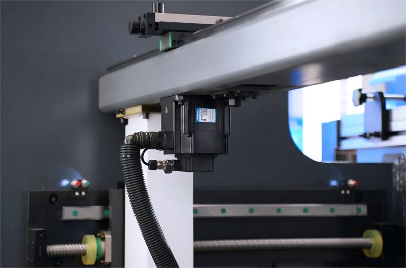
Identifisering van algemene persbrek-servostelsel-misfunksies
Voordat enige herstelwerk onderneem word, is die eerste kritieke stap om die spesifieke tipe servo-funksie wat op die CNC-beheerder aangedui word, te identifiseer. Moderne persbrekke maak hoofsaaklik gebruik van servo-motors vir twee kernfunksies: om die agtermaatstelsel aan te dryf en hidrouliese sinkronisasiebeheer moontlik te maak.
Tipiese Servo-alarmmodusse in CNC-persbrekke
Die mees algemene servo-alarme wat met persbrekstelsel-funksieprobleme geassosieer word, sluit die volgende in:
• Servo-oortolligheid-alarms
• Enkoder-kommunikasieprobleme
• Posisie-afwyking-alarms
• Servo-aandrywing oorverhitting
• Servo-motor oorstroombeskerming
Elke alarmtipe dui op ’n afsonderlike onderliggende oorsaak. Die interpretasie van die alarmkodes wat op gewilde beheerders (insluitend Delem-, ESA- en Cybelec-stelsels) vertoon word, is noodsaaklik om die foutsoekt proses te versnel en onnodige kontroles te vermy.
Stap-vir-stap-diagnostiese proses vir servo-stelsel-funksieprobleme in persbrekke
Die opsporing van probleme met die servo-stelsel vereis 'n gestruktureerde metodologie om onnodige komponentvervanging en minimum bedryfsafbreking te voorkom. Die volgende stap-vir-stap-proses verseker 'n logiese en doeltreffende diagnose.
2.1 Hersien Servo-aandrywingalarmkodes
Die aanvanklike stap is om die waarskuwingboodskappe wat op beide die servo-aandryfpaneel en die CNC-beheerder vertoon word, te kontroleer. Die meeste servo-aandrywings is toegerus met besonderhede diagnosekodes wat kritieke aanwysings oor die fout verskaf. Dit is noodsaaklik om drie sleutelstukke inligting te dokumenteer:
• Die spesifieke waarskuwingkode nommer
• Die masjien se bedryfstoestand toe die waarskuwing geaktiveer is (bv. stilstand, buiging, agtermaatinstelling)
• Die betrokke as (bv. X-as agtermaat, R-as hoogte-instelling)
Hierdie dokumentasie verklein onmiddellik die moontlikheid dat die fout van elektriese probleme, meganiese probleme of verkeerde parameterkonfigurasies afkomstig is.
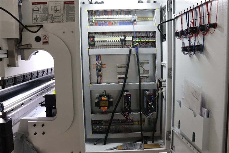
2.2 Ondersoek Servomotorbedrading en Verbindingsinterfaces
Losse of beskadigde kabels is een van die mees algemene oorsake van foutiewe werking van persbreek-servostelsels. 'n Deeglike inspeksie moet fokus op:
• Servomotor-kragkabels
• Enkoder-terugvoerkabels
• Terminaalblokke binne die elektriese beheerkabinet
Aanhouende masjienvibrasie tydens langtermynbedryf kan verbindings en terminale geleidelik losmaak. Dit is dikwels genoeg om los verbindings vas te trek en verslette of beskadigde kabels te vervang om onderbrekende servofoute wat anders moeilik is om op te spoor, te herstel.
2.3 Verifieer Enkoderterugvoersignale

Servomotors hang af van akkurate enkoderterslag om die hoë-presisieposisionering te handhaaf wat vir persbreekbedryf vereis word. Ongestabiel enkodertekens sal 'n reeks foutiewe werking veroorsaak, insluitend:
• Posisie-afwyking-alarms
• Asinkronisasiefoute
• Skielike, onbeplande afskakeling van die servomotor
Om kodeerderprobleme te diagnoseer, moet alle kodeerderverbindings vir styfheid ondersoek word en kabels vir oliebesmetting, skurings of ander meganiese beskadiging geïnspekteer word. Indien visuele inspeksie geen aanwysings lewer nie, gebruik die servo-aandrywing se ingeboude diagnostiese spyskaart om 'n sein-toets uit te voer en die kodeerder se funksionaliteit te bevestig.
Meganiese Oorsake van Persbreek-servo-stelsel-misfunksies
Nie alle servo-stelsel-misfunksies is elektries van aard nie—oormatige meganiese weerstand is 'n algemene en dikwels oorheen gesien oorsaak van servo-alarme. Die hantering van meganiese probleme is noodsaaklik om normale servo-bedryf te herstel en herhalende foute te voorkom.
3.1 Wrywingsweerstand in Agtermaatlynriglyne
Die agtermaat se lineêre rigtingsrails is geneig om stof, metaalsnippers en rommel tydens daaglikse bedryf op te hoop; ontoereikende smeermiddel vererger hierdie probleem. Wanneer weerstand opbou, moet die servo-motor ekstra krag uitoefen om die agtermaat-as te beweeg, wat dikwels veroorsaak:
• Servo-oortolligheid-alarms
• Abnormale oorverhitting van die servo-motor
• Traag agtermaat-posisioneringstempo
Die riglyne grondig skoonmaak om alle rommel te verwyder en die vervaardiger-aanbevole smeermiddel op die kogledeurskruwe en riglynkomponente aan te bring, verminder wrywingsweerstand drasties en herstel die servostelsel se normale bedryfstoestand.
3.2 Mislyn van kogleierskroewe
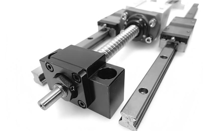
Verkeerde installasie tydens masjienopstelling of slytasie as gevolg van langdurige gebruik kan kogledeurskruwmiselyning veroorsaak—‘n ander groot bron van meganiese weerstand. Om hierdie probleem te diagnoseer, moet die volgende sleutelkomponente ondersoek word:
• Die reguitheid van die kogledeurskruwe self
• Die uitlyning van die koppeling wat die servomotor met die kogledeurskruwe verbind
• Die slytvlakke van die lager aan albei ente van die kogledeurskruwe
Die korrigering van kogledeurskruwmiselyning en die vervanging van verslete lager elimineer oormatige las op die servomotor, wat oorbelastingalarms voorkom en die motor se dienslewe verleng.
Servoparameterfoute en kalibrasietekortkominge
Verkeerde servo-parameterkonfigurasies is 'n hoofoorsaak van persbreek-servo-stelselprobleme, veral na masjienonderhoud, komponentvervanging of CNC-software-opdaterings. Selfs klein afwykings van die aanbevole parameters kan die hele servo-stelsel ontwrig.
4.1 Probleme met die opstel van servo-parameters
Verkeerd gekonfigureerde parameters wat verband hou met versnelling, spoedbeperkings of posisietoleransies sal onmiddellik servo-alarme aktiveer en die werking van die masjien belemmer. Sleutelparameters wat gevalideer en herkalibreer moet word, sluit in:
• Servo-versterkingsparameters
• Versnellings- en vertraaginstellings
• Posisie-afwykingstoleransiedrempels
Alle parameters moet op die presiese waardes ingestel word wat deur die persbreekvervaardiger aanbeveel word om naadlose werking van die servo-stelsel te verseker.
4.2 Afwykings in die kalibrasie van die agtermaatposisie
Indien die agtermaat se posisieverwysingspunt onakkuraat word as gevolg van meganiese beweging of elektriese probleme, sal die CNC-beheerder abnormale posisie-afwyking opspoor en 'n alarm aktiveer. Om hierdie probleem op te los, moet 'n volledige kalibrasieproses uitgevoer word wat die volgende insluit:
• As-huistellingkalibrasie om die nulpunt te herstel
• 'n Volledige herstel van die agtermaat se posisieverwysing
• Verifikasie van posisieakkuratese met behulp van presisie-metingsinstrumente
Behoorlike kalibrasie verseker dat die servo-stelsel binne die vervaardiger se gespesifiseerde toleransiebereik bedryf word, wat vals posisie-afwykingalarms elimineer.
Voorkomende Strategieë om Servo-stelselbederf te Verminder
Die voorkoming van servo-stelselbederf in 'n persbreek is baie doeltreffender en koste-effektiewer as die herstel daarvan tydens onbeplande produksiestaking. Die implementering van 'n proaktiewe voorkomende onderhoudprogram is die beste manier om langtermyn-stabiliteit van die servo-stelsel te verseker.
5.1 Geprogrammeerde elektriese inspeksies
Gereelde inspeksies van die elektriese beheerkabinet en die servo-stelsel se elektriese komponente is noodsaaklik. Fokus op die versekering van:
• Onbelemmerde en doeltreffende verkoeling van die servo-aandrywing
• Skoon ventilasiefilters om stofopbou te voorkom
• Veilige, stywe verbindinge vir al die elektriese terminale en kabels
Stofopbou in die beheerkabinet kan oorverhitting en kommunikasie-onstabiliteit veroorsaak, wat lei tot aan-uit of volgehoue servo-funksieprobleme. Weeklikse visuele inspeksies en maandelikse diep skoonmaak word aanbeveel.
5.2 Smeer en meganiese onderhoud
Behoorlike smeermiddeltoediening aan al die bewegende meganiese komponente verminder die las op die servo-motor aansienlik en voorkom oormatige slytasie. Kernonderhoudstake sluit in:
• Gereelde skoonmaak van kogel-skroewe om rommel te verwyder
• Geplanne smeermiddeltoediening aan lineêre geleidingrails met die korrekte smeermiddel
• Tydige verwydering van metaalsnawwe en rommel van al die bewegende dele van die agtermaat- en buigstelsel
Hierdie rutynonderhoud verwyder onnodige meganiese spanning op die servo-stelsel en verminder die risiko van oorbelasting- en oorverhittingwaarskuwings.
5.3 Tydsgelyke monitering van servo-temperatuur en -las
Byna alle moderne CNC-persremkontrollere bied werkliktyds moniteringsfunksionaliteit vir die servo-motor se temperatuur en lasvlakke. Operateurs en onderhoudspanne moet hierdie metrieke gereeld nakien; enige abnormale, skielike styging in temperatuur of las dui op 'n onderliggende probleem (bv. meganiese weerstand, bedradingfoute).
Die ondersoek en onmiddellike oplossing van hierdie waarskuwingstekens voorkom dat klein probleme uitgroei na groot servo-stelselstoringe en onbeplande produksie-uitval.
Gereelde vrae
6.1 Wat is die mees algemene oorsake van servo-stelselfoute by persbremse?
Gebaseer op praktiese nydervaring in die bedryf, is die drie mees algemene oorsake los enkoderterugvoerkabels, onvoldoende smeermiddel op die meganiese komponente van die agtermaat, en verkeerde servo-parameterkonfigurasies. Hierdie drie probleme is verantwoordelik vir die grootste gedeelte van servo-waarskuwings tydens daaglikse bedryf.
6.2 Kan meganiese weerstand servo-alarme aktiveer?
Ja, meganiese weerstand is 'n groot aanleiding vir servoalarms. Wanneer kogel-skroewe, lineêre geleidingrails of ander bewegende komponente vuil word, verkeerd uitgelig is of verslet raak, word die servo-motor gedwing om onder buitensporige las te werk. Hierdie ekstra las aktiveer direk servo-oorbelastingalarms en kan ook sekondêre probleme soos motoroortemperatuur veroorsaak.
6.3 Wat is die vinnigste manier om 'n servostelsel-misfunksie te diagnoseer?
Begin deur die servo-aandrywer se alarmkode te neem en te interpreteer—dit is die een belangrikste stap om die foutaanleiding te beperk. Volgende moet alle bedrading en enkoder-verbindinge vir losheid of beskadiging ondersoek word, gevolg deur 'n ondersoek na buitensporige meganiese weerstand op die betrokke as. Pas slegs servo-parameterinstellings aan nadat elektriese en meganiese probleme uitgesluit is om onnodige parameterveranderings te voorkom.
6.4 Hoe dikwels moet die persbrek-servostelsel ondersoek word?
Vir gereelde vervaardigingsomgewings word 'n basiese visuele inspeksie van die servo-stelsel (insluitend bedrading, verbindings en skoonheid van meganiese komponente) weekliks aanbeveel. 'n Meer omvattende voorkomende onderhoudsinspeksie—insluitend smeer, toets van enkoder-seinale, verifikasie van parameters en kalibrasie van temperatuur/las-sensore—moet maandeliks uitgevoer word.
Gevolgtrekking
Drukbreuk-servo-stelselprobleme kan vervaardigingsprogramme ontwrig en die presisie van metaalbuigbewerkings in gevaar stel, maar die grootste meerderheid van hierdie probleme kan vinnig en doeltreffend opgelos word met 'n gestruktureerde, stap-vir-stap fouteopsporingbenadering. Deur eers servo-waarskuwingkodes te interpreteer, dan bedrading en enkoder-terugvoerseine te ondersoek, oormatige meganiese weerstand uit te skakel en servo-parameterkonfigurasies te verifieer, kan operateurs en onderhoudspanne die meeste foute akkuraat identifiseer en met minimale afbreektyd regstel.
Proaktiewe, gereelde voorkomende onderhoud is die hoeksteen van langtermyn-stabiliteit en betroubaarheid van servostelsels. Deur aan geskeduleerde elektriese inspeksies, konsekwente meganiese smeer- en onderhoudswerk, sowel as real-time monitering van servo-temperatuur en -las vas te hou, kan besighede die frekwensie van servo-foutwerking drasties verminder en hul JUGAO persbreekbedryf glad laat vaar. Vir aanhoudende of ingewikkelde servostelselprobleme wat nie met basiese foute-opsporing opgelos kan word nie, word dit aanbeveel om 'n professionele tegniese ondersteuningspan te raadpleeg om akkurate diagnose en doeltreffende oplossing te verseker, wat produksieverliese tot 'n minimum beperk en die masjien se langtermynprestasie beskerm.

